

AutoCAD & AutoCAD LT All-In-One Desk Reference For Dummies (2006)
.pdf272 Making the Trip from AutoCAD to AutoCAD LT
Figure 3-1:
The External References palette.
3D modeling
The ability to work with drawings that contain 3D solids and surfaces is very limited in AutoCAD LT. In AutoCAD, you have many different ways to modify 3D solids and surfaces, such as through the use of grips, the SOLIDEDIT command, and others; these are not available in AutoCAD LT. AutoCAD LT doesn’t allow you to create and modify 3D solids and surfaces besides using basic modifying commands such as move, copy, and rotate. You are limited to changing only general properties of 3D solids and surfaces, such as their color, what layer they are on, and the other general properties that are available for the object. However, a 3D solid or surface can be exploded into wireframe models that are made up of regions or 2D objects.
If a drawing has a section plane and Live Section is enabled for the section plane, it won’t look the same in AutoCAD LT as it does in AutoCAD (see Figure 3-2). The Live Section is not displayed, but the section plane will exist in AutoCAD LT, so if the drawing is saved and reopened in AutoCAD, it looks just like it did before it was opened in AutoCAD LT. For more information on 3D solids and surfaces, see Chapters 4 through 6 of Book V.
Figure 3-2:
Live Section enabled in AutoCAD, and how it looks in AutoCAD LT.

Making the Trip from AutoCAD to AutoCAD LT 273
Annotation
AutoCAD and AutoCAD LT have very few differences in annotation. The two main differences that you have to be concerned about when exchanging drawing files between AutoCAD and AutoCAD LT are gradient fills and fields. Both gradient fills and fields are displayed in AutoCAD LT without any problems, but they can’t be created or edited. If you use the HATCHEDIT command on a gradient fill, it turns into a solid fill. If you change the boundary associated to the gradient fill, it continues to exist as a gradient fill in the drawing.
Fields are used to associate properties of a drawing file or objects in the drawing with a text, multiline text, or an attribute. Fields can help make sure that information remains in sync when something is changed in the drawing or an object is modified. Based on the type of field, it either displays the last value or it updates based on changes in the drawing file. The expression that the field is created with can’t be modified, but you can replace the field with plain text. That isn’t recommended. If the field is replaced with plain text, however, it breaks the functionality that the field provided if the drawing is opened back in AutoCAD. For more information on hatch in a drawing, see Chapter 3 of Book III; for more information on Fields, see Chapter 1 of Book III.
Viewing
Cameras are displayed as glyphs in AutoCAD and are accessible from either the drawing window or the View Manager dialog box. AutoCAD LT doesn’t display camera glyphs in the drawing, but it does list the camera in the View Manager dialog box. AutoCAD LT also is missing several properties that are available for a named view in AutoCAD. These properties are for things like backgrounds and live sections, which are not supported in AutoCAD LT.
Visualization
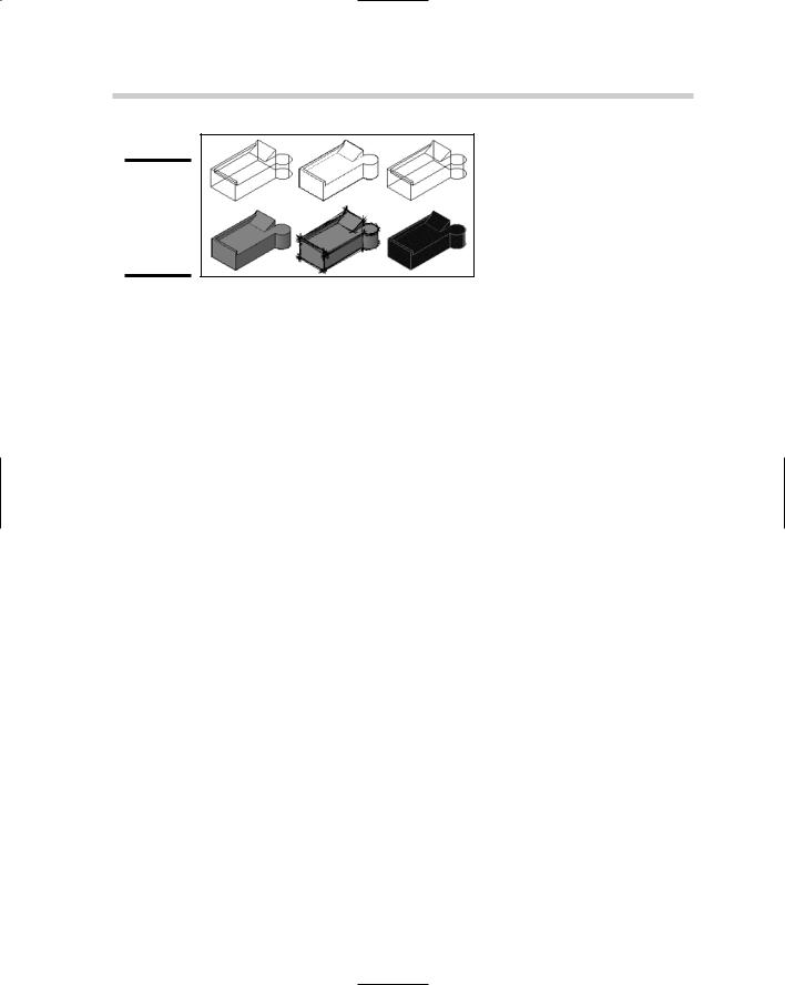
Drawings created with AutoCAD can contain a variety of additional objects and settings that really don’t do anything in AutoCAD LT: One example is lights. Lights appear in the drawing and can be selected and modified via grips, but their properties can’t be altered. Because AutoCAD LT lacks the ability to do renderings, you won’t be able to use any material assignments that are on objects or be able to modify the materials that are stored in a drawing file. This can cause problems if a viewport on a layout tab is set up to use the Realistic visual style that AutoCAD offers. For the most part, all visual styles are supported by AutoCAD LT, with the exception of Realistic (see Figure 3-3). The visual styles can’t be changed, but if they are assigned to a viewport on a layout tab, they will be displayed correctly.
Book IV
Chapter 3
MixedEnvironments
274 Making the Trip from AutoCAD to AutoCAD LT
Figure 3-3:
Visual styles saved with a drawing are displayed in AutoCAD LT.
CAD Standards
The CAD Standards feature of AutoCAD uses Drawing Standards (DWS) files that are associated with the drawing file, but AutoCAD LT doesn’t use or know about these files. This isn’t a problem with AutoCAD LT because the feature doesn’t exist in LT, but it can become a nightmare if you work on a set of drawings and use the eTransmit feature to repackage them up to send them off to someone else. Because AutoCAD LT doesn’t know about these types of files, it doesn’t know enough to inform you that they might be missing or are needed when sending off a set of drawings.
Collaboration/sharing
Collaboration plays a large role in designing a new building, creating a new machine, or engineering a new bridge. All these things and many more don’t just happen by themselves: They require collaboration. AutoCAD allows you to create a Sheet Set of all the drawing files that are related to a project and maintain links from model views to drawing layouts. AutoCAD LT doesn’t support the use of Sheet Set (DST) files because it doesn’t have the Sheet Set Manager palette, so any values that reference part of the Sheet Set file through fields can’t be updated. If a field value needs to be changed, it must be replaced with plain text, which causes problems if it is reopened later in AutoCAD.
Book V
3D Modeling

Contents at a Glance |
|
Chapter 1: Introducing the Third Dimension .................................................................. |
277 |
Chapter 2: Using the 3D Environment .............................................................................. |
285 |
Chapter 3: Viewing in 3D .................................................................................................. |
297 |
Chapter 4: Moving from 2D to 3D...................................................................................... |
307 |
Chapter 5: Working with Solids ........................................................................................ |
321 |
Chapter 6: Working with Surfaces .................................................................................... |
329 |
Chapter 7: Rendering: Lights, Cameras, AutoCAD!.......................................................... |
337 |

Chapter 1: Introducing
the Third Dimension
In This Chapter
Understanding the different types of 3D models
Entering coordinates above the x,y plane
This book of the AutoCAD & AutoCAD LT All-in-One Desk Reference For Dummies takes you on a journey to a whole new dimension. No, we are
not talking about space or time travelling to a different location, but rather giving your drawings some depth. AutoCAD is a very powerful 2D drafting tool, but it also sports a nice set of tools for 3D modeling. AutoCAD LT, unlike its older counterpart, has limited 3D drafting, visualization, and viewing capabilities. Most of what is discussed in the chapters of this book is geared toward AutoCAD only; but there are some things that apply to AutoCAD LT, and we point those out to you.
Most of us think best when drafting in 2D, but this is most likely due to a comfort level that we have from learning 2D drafting first and therefore, making 3D drafting seem somewhat foreign and difficult. In reality, 3D drafting is not all that difficult — much of what was covered in early chapters applies to 3D drafting.
AutoCAD allows you to create three types of 3D models: wireframe, solid, and surface. AutoCAD LT is only capable of creating and editing wireframe models, but you can use it to view solid and surface models.
Throughout the chapters in this book, you see how to select points above the x,y coordinate plane, and how to adjust and manipulate the coordinate system to more easily use drafting commands. After you have mastered selecting points in the drawing and working with the coordinate system,
we take you on a tour of some of the navigation and viewing commands that AutoCAD and AutoCAD LT offer for viewing 3D models. After you have the basics under your belt, we show you how to use many of the different modeling and editing commands that are used with solids and surfaces. To close out the chapter, we touch on the concepts of creating renderings from AutoCAD.
278 Understanding the Different Types of 3D Models
Understanding the Different Types of 3D Models
AutoCAD and AutoCAD LT allow you to create and view drawings that are created as wireframe, surface, or solid models. These different types of models each have their own strengths and weaknesses.
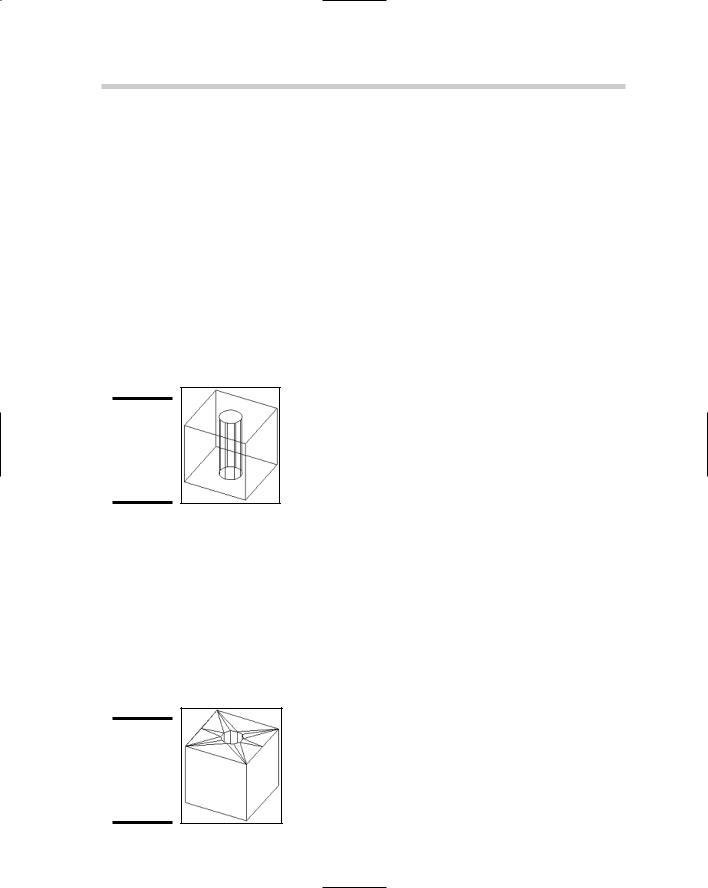
Wireframe model: Wireframe models are created with the use of 2D objects such as lines, arcs, polylines, and circles with no thickness. The 2D objects are drawings in 3D space using full x, y, and z coordinates, not just x- and y-coordinate values. Wireframe models are not intended to be used for visualization, as they do not have any surface area that allows them to hide objects beyond the geometry that they represent. Wireframe models provide for a great starting point when creating surface models. Figure 1-1 shows a cube with a hole drawn as a wireframe model and displayed with the HIDE command. You can think of a wireframe model as being much like a wire hanger.
Figure 1-1:
Wireframe model of a cube with a hole in the center.
Surface model: Surface models are created from 3D objects called faces. Faces can be made up of three or four points. Unlike wireframe models, surface models can be used for visualization. However, based on the type of visualization such as a hidden line drawing, some clean up might be necessary to hide the edges of faces that form a surface. AutoCAD offers several commands that allow you to create and manipulate surfaces. Figure 1-2 shows a cube with a hole drawn as a surface model and displayed with the HIDE command. The HIDE command shows the surfaces and edges of the surface model. You can think of a surface model as being much like a cardboard shipping box: It is hollow on the inside.
Figure 1-2:
Surface model of a cube with a hole in the center.
Entering Coordinates above the x,y Plane 279
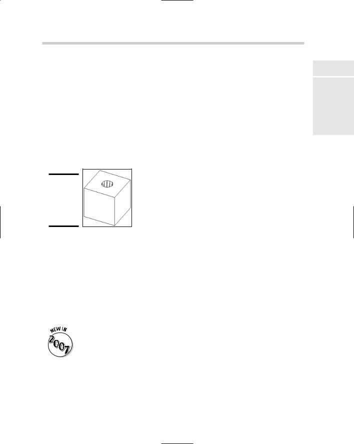
Solid model: Solid models are created from 3D objects called solids (“primitives”). Solid objects are much more flexible than faces and 2D objects for creating wireframe and surface models. Solid objects can be created and modified through a number of commands in AutoCAD. These commands allow you to create primitive objects such as cubes, spheres, and cones, and then combine them to form compound objects. Unlike surfaces, solids do have mass and therefore are not hollow, which allows you to capture information about them. Solids are much easier to work with than surfaces. Figure 1-3 shows a cube with a hole drawn as a solid model and displayed with the HIDE command. The HIDE command shows the surfaces and edges of the solid model. You can think of a solid model as being much like a block of solid wood: It is not hollow on the inside unless you core it out.
Figure 1-3:
Solid model of a cube with a hole in the center.
Entering Coordinates above the x,y Plane
Everything you have done up to this point has been with x- and y- coordinate values. This is all about to change as you step in a whole new direction with the z coordinate. Most of AutoCAD’s commands are not true 2D commands; this means that commands like a PLINE for creating a Polyline can only be drawn at a single z height (or elevation). Out of what are known as the traditional 2D commands, only the LINE command allows you to specify
two different z heights for the start and end points for the object that is being created with the command.
Orthographical (Ortho) mode has been improved for use with 3D drafting in AutoCAD 2007, and not AutoCAD LT 2007. You are now able to drag the crosshairs up or down after you specify the first point when orthomode is enabled, to specify the next point in the z direction. A tooltip is displayed to tell you which direction from the first point you are moving in.
Manually inputting coordinates
Book V
Chapter 1
the IntroducingDimension Third
Chapter 6 of Book I explains how to input relative and absolute coordinates for 2D drafting. Both of these coordinate formats are great for both 2D and 3D drafting. The only difference that you will find when doing 3D drafting is

280 Entering Coordinates above the x,y Plane
the need to enter a z coordinate value. Along with those coordinate input formats, the relative polar coordinate input is expanded to include two additional formats called cylindrical and spherical designed for 3D drafting. Of course, you can use object snaps, point filters, and object snap tracking when creating and modifying 3D objects.
You can input coordinate values through the use of Direct Distance Entry and the using of Dynamic Input. Both of these are covered in Chapters 2 and 6 of Book I.
Absolute x, y, and z coordinates
Working with absolute coordinates in 3D drafting is just like you would input them for 2D drafting, except you add in the z coordinate. You supply the coordinate input in the format x,y,z. An example of using the LINE command to drawing a line in 3D space using absolute coordinate entry is shown below.
Command: line
Specify first point: 0,0,0
Specify next point or [Undo]: 2,3,7.25
Relative x, y, and z coordinates
Working with relative coordinates in 3D drafting is just like when inputting them for 2D drafting, except you add in the z coordinate. You supply the coordinate input in the format of @x,y,z. An example of using the LINE command to drawing a line in 3D space using relative coordinate entry is shown below.
Command: line
Specify first point: 2.125,7,-3
Specify next point or [Undo]: @0.5,0.125,7
Cylindrical coordinates
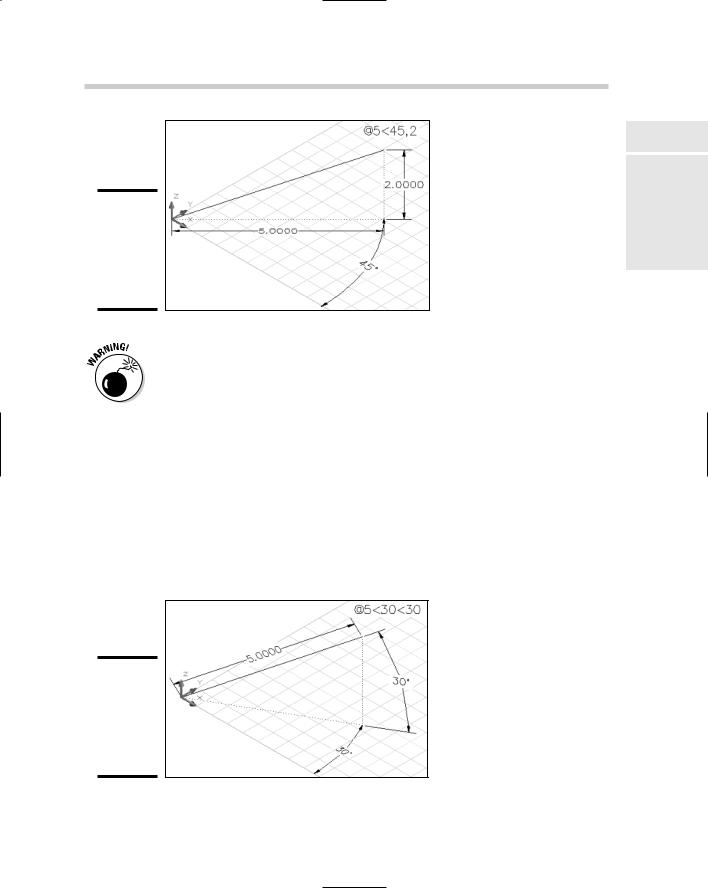
Cylindrical coordinates is the first of two coordinate entry formats based on relative polar coordinate entry for 3D drafting. You supply the coordinate input in the format of @XYdistance<angle,Z. An example of using the LINE command to draw a line in 3D space using cylindrical coordinate entry is shown below. Figure 1-4 shows the results in AutoCAD.
Command: line
Specify first point: 0,0,0
Specify next point or [Undo]: @5<45,2
Entering Coordinates above the x,y Plane 281
Figure 1-4:
Line created in 3D space using cylindrical coordinate input.
Cylindrical coordinate input doesn’t work very well when Dynamic Input is enabled. We recommend turning it off by clicking the DYN button on the status bar area or pressing F12 when wanting to use cylindrical coordinate input.
Spherical coordinates
Spherical coordinates is the second of the two coordinate entry formats that is based on relative polar coordinate entry for 3D drafting. You supply the coordinate input in the format of @XYdistance<angle<anglefromXY. An example of using the LINE command to draw a line in 3D space using spherical coordinate entry is shown below. Figure 1-5 shows the results in AutoCAD.
Command: line
Specify first point: 0,0,0
Specify next point or [Undo]: @5<30<30
Figure 1-5:
Line created in 3D space using spherical coordinate input.
Book V
Chapter 1
the IntroducingDimension Third