

AutoCAD & AutoCAD LT All-In-One Desk Reference For Dummies (2006)
.pdf242 Adding Hatch Patterns and Fills
Figure 3-1:
Hatch patterns and fills.
Adding Hatch Patterns and Fills
Hatch objects are created using the Hatch and Gradient dialog box (see Figure 3-2), or, if you are using AutoCAD LT, the Hatch dialog box. The Hatch and Gradient dialog box allows you to specify which hatch pattern or fill should be used to hatch a closed boundary (or area). Based on the type of hatch you are creating, you might need to specify a pattern, scale, and angle.
Many different settings control how a hatch object looks after it is created. Most of the commonly used settings for creating and editing hatch objects are displayed by default, but if you want to access some of the more advanced settings, click the More Options button.
Figure 3-2:
The Hatch and Gradient dialog box with the Hatch tab active and expanded.
More Options
Adding Hatch Patterns and Fills 243
Adding hatch to a drawing
Adding hatch to a drawing the first few times can be a little bit confusing, but that is to be expected because many elements in a drawing and the dialog box can affect how a hatch object is created. When you want to create a hatch object, make sure that the area you want to hatch is closed — meaning all lines, arcs, and so on define a boundary either by connecting at the end points of the objects or by overlapping each other. Hatch objects are created using the Hatch and Gradient dialog box, which is displayed with the HATCH command.
To start the HATCH command and display the Hatch and Gradient dialog box, follow one of these methods:
Draw menu: Choose Draw Hatch.
Draw toolbar: Click Hatch on the Draw toolbar.
Keyboard input: Type HATCH and press Enter.
Command Alias: Type H and press Enter.
The following procedure starts the Draw command and displays the Hatch and Gradient dialog box so you can create a hatch object using a predefined hatch pattern:
1.Use one of the methods just listed to start the Draw command.
The Hatch and Gradient dialog box is displayed.
2.In the Hatch and Gradient dialog box under the Type and Pattern section, select Predefined from the Type drop-down list.
The controls that are used with a predefined hatch pattern are enabled.
3.From the Pattern drop-down list, select one of the predefined hatch patterns.
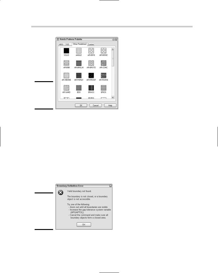
A preview of the selected hatch pattern is displayed in the Swatch area below the Pattern drop-down list. You can click the ellipsis button to the right of the Pattern drop-down list to display the Hatch Pattern Palette dialog box (see Figure 3-3). The Hatch Pattern Palette dialog box allows you to select predefined and custom hatch patterns that come with the software.
4.Under the Angle and Scale section, specify an angle for the hatch pattern by selecting a predefined value from the Angle drop-down list or entering a value in the text box.
Book III
Chapter 3
HatchingDrawings
Your
244 Adding Hatch Patterns and Fills
Figure 3-3:
The Hatch Pattern Palette dialog box.
5.Specify a scale for the hatch pattern by selecting a predefined value from the Scale drop-down list or entering a value in the text box.
6.Under the Boundaries section, click Add: Pick Points.
You are returned to the drawing window to pick a point inside the closed boundary. The prompt Pick internal point or [Select objects/remove Boundaries]: is displayed.
7.At the prompt, click in the drawing window within a closed boundary to define the boundary for a hatch object.
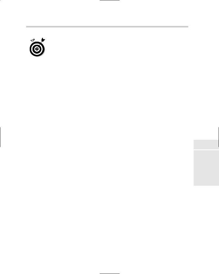
The boundary is calculated, and you are prompted for additional closed areas. If the area is not closed or the boundary can’t be calculated, a message box is displayed (see Figure 3-4).
Figure 3-4:
The Boundary Definition Error message box.
Adding Hatch Patterns and Fills 245
The system variable HPGAPTOL specifies if a tolerance value is used when calculating a closed boundary with objects that don’t completely form a closed boundary. The value can also be specified under the Gap Tolerance section when the Hatch and Gradient dialog box is expanded.
8.Press Enter to accept the selected boundaries and to return to the Hatch and Gradient dialog box.
9.In the Hatch and Gradient dialog box, click Preview.
The hatch object is displayed in the drawing.
10.Press ESC to return to the Hatch and Gradient dialog box to make changes or press Enter to create the hatch object.
The hatch object is created and the command ends.
Hatching and tool palettes
You can create hatch tools on a tool palette that can be used to create new hatch objects in a drawing. A hatch tool can be created by dragging and dropping a hatch object from a drawing onto a tool palette. The hatch tool is created based on the properties of the hatch object. To use the hatch tool, click the tool and then click inside the closed boundary, or drag and drop the tool over the closed boundary. For more information on tool palettes, see Chapter 4 of Book VI.
Hatching and DesignCenter
Hatch objects and hatch tools can be created from the DesignCenter. To create a hatch object or a hatch tool, browse to the location where the hatch pattern (.PAT) files are stored with DesignCenter. Double-click the hatch pattern file, and then drag and drop the hatch pattern over a closed boundary or over a tool palette.
Advanced settings for additional control
The Hatch and Gradient dialog box offers a number of options to control how a hatch object is created and how the boundary for a hatch object is generated. These options can be found under the Hatch Origin and Options sections and under the extended section of the Hatch and Gradient dialog box.
Specifying the origin for a hatch object
The Hatch Origin section allows you to define the base point in the drawing from which the hatch pattern is calculated. By default, the origin point of the drawing is used, instead of a point in the closed boundary. The Specified Origin option allows you to select the point that should be used for the origin that the hatch pattern of the hatch object should be calculated from.
Book III
Chapter 3
HatchingDrawings
Your
246 Adding Hatch Patterns and Fills
Specifying an origin point allows you to make the appearance of hatch patterns predictable. This is important if you are using hatch patterns for creating tiles, bricks, and siding on a house; for example, you want to make sure you have a full run of bricks at the bottom of a house, and not just half of a run.
Island detection
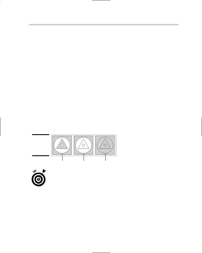
Island detection is used when calculating the closed boundary for a hatch object. An island is defined as an interior boundary inside the outer boundary that is calculated. To access the island detection settings, you have to click the More Options button that is located in the lower-right corner of the Hatch and Gradient dialog box. Figure 3-5 shows examples of the three island detection options:
Normal: The outer detected boundary is hatched, but hatch is turned off for any detected island until another island is detected.
Outer: Only the outer detected boundary is hatched; no hatch is applied to islands inside the boundary calculated.
Ignore: All islands are ignored and the hatch fills the entire area defined by the outer boundary.
Figure 3-5:
Island detection settings.
Normal |
Outer |
Ignore |
The Remove Boundaries button allows you to remove and add islands to adjust the boundary of a hatch object when it is being edited.
Others settings available for defining a hatch object
Some additional settings allow you to specify a factor that should be used when defining a boundary that might not be completely closed. Another setting allows you to create separate hatch objects for each closed boundary that is defined when selecting objects or points to define boundaries. Another nice feature is to define the order in which the hatch object is displayed on-screen in respect to the objects that define its boundary. For additional information on the options of the Hatch and Gradient dialog box, see the online Help system.
Working with Hatch Patterns and Solid Fills 247
A new system variable now controls whether object snaps can be used with hatch objects. If the system variable OSOPTIONS is set to a value of 1 or 3, object snaps are ignored for hatch objects.
Working with Hatch Patterns and Solid Fills
Hatch patterns and solid fills are the most commonly used types of hatches. AutoCAD and AutoCAD LT offer three different types of hatch patterns that you can use when adding hatch to a drawing: predefined, user-defined, and custom.
Predefined patterns
AutoCAD and AutoCAD LT come with a number of predefined patterns that are available in the files acad.PAT (acadiso.PAT for metric) and acadlt.PAT (acadltiso.PAT for metric). To use a predefined hatch pattern or solid fill, select Predefined from the Type drop-down list. The Pattern drop-down list is enabled, which allows you to select a pattern from the drop-down list. Alternatively, click the ellipsis button to the right of the Pattern drop-down list to select a pattern visually from the Hatch Pattern Palette dialog box.
The system variable MEASUREMENT is used to control which hatch pattern and linetype files are used for imperial or metric drawings. If MEASUREMENT is set to a value of 0, the imperial files are used; a value of 1 indicates that the metric files should be used.
User-defined patterns
User-defined hatch patterns are not very common because they just don’t offer much more than what the predefined hatch patterns offer. When defining a user-defined hatch pattern, you specify the spacing and angle of lines that run parallel or perpendicular to each other. One of the nice things about user-defined hatch patterns is that you specify the actual spacing of the lines in drawing units instead of a scale factor. To create a user-defined hatch pattern, select User Defined from the Type drop-down list. After User Defined is selected, set the angle and spacing values and specify whether double lines should be created.
Custom hatch patterns
Custom hatch patterns are typically supplemental patterns that offer something that is not available from the predefined hatch patterns that come with the application. Custom hatch patterns are usually much more complex than just a series of lines that can be generated as a user-defined pattern. Custom hatch pattern files must be placed in one of the support paths defined under the Files tab of the Options dialog box.
Book III
Chapter 3
HatchingDrawings
Your
248 Using Gradient Fills
To use a custom hatch pattern, select Custom from the Type drop-down list and then click the ellipsis button next to the Custom drop-down list to display the Hatch Pattern Palette dialog box. The Custom tab is set current and displays the hatch patterns that AutoCAD or AutoCAD LT automatically found in the support paths. For more information on custom hatch patterns, see Chapter 4 of Book IX.
Using Gradient Fills
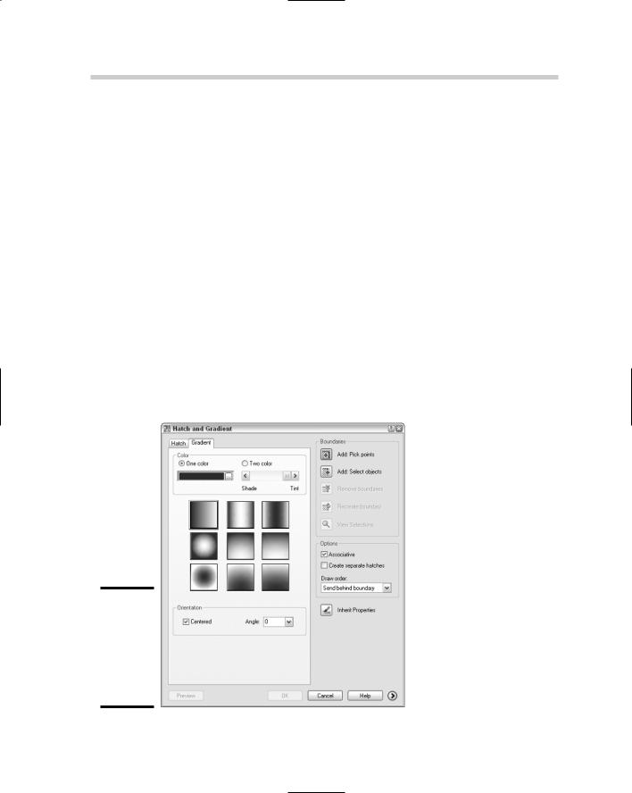
Gradient fills were added to AutoCAD 2004 to replace the fills that users had previously been creating with external paint applications. Gradient fills are created based on a choice of one color and a tint value or two colors, the direction of the color shift, whether the gradient is centered, and its angle. Gradient fills are created from the Gradient tab of the Hatch and Gradient dialog box (see Figure 3-6).
Creating a gradient fill isn’t much different from creating a hatch object that uses a predefined, user-defined, or custom pattern. After the basic characteristics of the gradient fill have been defined, you define the boundary for the hatch in the same way you would for creating one of the hatch types from the Hatch tab.
Figure 3-6:
The Hatch and Gradient dialog box with the Gradient tab active.
Editing Hatch Patterns and Fills 249
Gradient fills can’t be applied with AutoCAD LT, but are displayed in LT with no problem.
If a drawing is saved back to AutoCAD 2002 or earlier versions, gradient fills are displayed as a solid fill. The color of the solid fill is based on the closest ACI color to the first color of the gradient fill.
Editing Hatch Patterns and Fills
Editing a hatch object is very similar to editing a text object or other objects. Double-clicking a hatch object starts the HATCHEDIT command, which allows you to edit a hatch object. Alternatively, you can start the HATCHEDIT command by selecting and right-clicking a hatch object and choosing Hatch Edit from the shortcut menu. The HATCHEDIT command displays the Hatch Edit dialog box, which is identical to the Hatch and Gradient dialog box, except that some of the options used only for creating a hatch object are disabled. Make the necessary changes and click OK to apply the changes.
The MATCHPROP command is great for making one or more hatch objects look the same by copying the properties from one hatch object to another.
Book III
Chapter 3
HatchingDrawings
Your
250 Book III: Annotating Drawings

Book IV
LT Differences