

AutoCAD & AutoCAD LT All-In-One Desk Reference For Dummies (2006)
.pdf232 Creating Dimensions
Keyboard input: Type DIMARC and press Enter.
Command alias: Type DAR and press Enter.
Radius, diameter, and jogged dimensions
AutoCAD offers four different types of dimensions that are used to dimension the radius or diameter of a circle or arc, or place a center mark at the center point of a circle or arc. Figure 2-17 shows the results of using the commands DIMRADIUS, DIMDIAMETER, DIMCENTER, and DIMJOGGED on a circle or arc.
Radius dimension |
Center marks |
Figure 2-17:
Radius, diameter, and jogged dimensions along with center marks.
Diameter dimension |
Jogged dimension |
Radius dimensions
Radius dimensions display an uppercase R prefixed to the measurement value to designate that the measurement is for the radius and not the diameter of the arc or circle. When a radius dimension is placed, a center mark is also displayed so you know where the center of the object that is being dimensioned is. Radius dimensions are created using the DIMRADIUS command. To start the DIMRADIUS command, follow one of the methods outlined below:
Dimension menu: Choose Dimension Radius.
Dimension toolbar: Click the Radius button on the Dimension toolbar.
Keyboard input: Type DIMRADIUS and press Enter.
Command alias: Type DRA and press Enter.
Diameter dimensions
Diameter dimensions are similar to radius dimensions except they are used to measure the diameter of an arc or circle. The two dimensions look almost identical, except the diameter dimension displays a diameter symbol in front of the measurement value. Diameter dimensions are created using the DIMDIAMETER command. To start the DIMDIAMETER command, follow one of the methods outlined below:
Creating Dimensions 233
Dimension menu: Choose Dimension Diameter.
Dimension toolbar: Click the Diameter button on the Dimension toolbar.
Keyboard input: Type DIMDIAMETER and press Enter.
Command alias: Type DDI and press Enter.
Jogged dimensions
Jogged dimensions allow you to show the radius of an arc or a circle like a radius dimension does, except instead of the dimension automatically indicating the center of the object, you specify a center override location. When a jogged dimension is placed, no center mark is displayed, but an angle on the dimension line is displayed to indicate that the radius isn’t being measured from the center of the object. Jogged dimensions are created using the DIMJOGGED command. To start the DIMJOGGED command, follow one of the methods outlined below:
Dimension menu: Choose Dimension Jogged.
Dimension toolbar: Click the Jogged button on the Dimension toolbar.
Keyboard input: Type DIMJOGGED and press Enter.
Command alias: Type DJO and press Enter.
Center marks
Center marks allow you to place a set of lines at the center of an arc or a circle. The lines that are created are not a single dimension object, but a bunch of separate line objects. The type of center mark created is based on the settings under the Center Mark section of the Symbols and Arrows tab of the New/Modify Dimension Style dialog box. Center marks are automatically created when you place radius and diameter dimensions, but you want to place center marks at the center of circles when placing linear dimensions to indicate that you are dimensioning to the center of the circle. Center marks are created using the DIMCENTER command. After the DIMCENTER command is started, select an arc or circle to create the center mark. To start the DIMCENTER command, follow one of the methods outlined below:
Dimension menu: Choose Dimension Center Mark.
Dimension toolbar: Click the Center Mark button on the Dimension toolbar.
Keyboard input: Type DIMCENTER and press Enter.
Command alias: Type DCE and press Enter.
Book III
Chapter 2
Dimensioning
234 Creating Dimensions
Ordinate dimensions
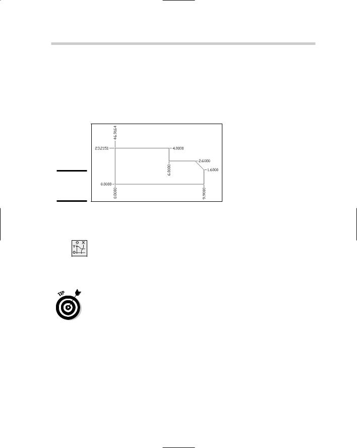
Ordinate dimensions (see Figure 2-18) allow you to place x and y coordinate values of features or specific points on a part. Each ordinate dimension represents an x or y value, but not both. Ordinate dimensions are not a commonly used type of dimension, but you might find them used on shop drawings used to manufacture parts.
Figure 2-18:
Ordinate dimensions.
Ordinate dimensions are created using the DIMORDINATE command. To start the DIMORDINATE command, follow one of the methods outlined below:
Dimension menu: Choose Dimension Ordinate.
Dimension toolbar: Click the Ordinate button on the Dimension toolbar.
Keyboard input: Type DIMORDINATE and press Enter.
Command alias: Type DOR and press Enter.
When you create ordinate dimensions, they are based on the origin of the current user coordinate system (UCS). (For more information on the User Coordinate System, see Book V, Chapter 2.) Usually a point on the part is designated as 0,0. In order to do that, you need to specify a new origin for the current UCS. To specify a new origin, start the UCS command and then pick the point in the drawing you want to be the current 0,0 value. To undo the moving of the origin, use the World option of the UCS command.
The Quick Dimension command
The Quick Dimension (QDIM) command allows you to quickly place a number of dimensions in a drawing by selecting multiple objects at a time. The QDIM command allows you to create linear, continuous, staggered, baseline, ordinate, radius, and diameter dimensions. To start the QDIM command, follow one of the methods outlined below:
Editing Dimensions 235
Dimension menu: Choose Dimension Quick Dimension.
Dimension toolbar: Click the Quick Dimension button on the Dimension toolbar.
Keyboard input: Type QDIM and press Enter.
The QDIM command is not available in AutoCAD LT.
Trans-spatial dimensions
Trans-spatial dimensions are not something you find in a science fiction novel, but instead a feature of AutoCAD that allows you to dimension objects that are in model space through a floating viewport. Trans-spatial dimensions allow you to place dimensions on layouts that measure accurately, but this brings up the question of where dimensions should be placed.
You should generally do dimensioning in model space (via the Model tab), but at times, you may find it beneficial to dimension objects that are in model space through a viewport. One of the main reasons that dimensions should be placed in model space is so they appear if the drawing is inserted or referenced into another drawing. In order to dimension objects correctly, the scale used for the dimension style should be set to a value of 1.
Before you attempt to take on dimensioning on a layout tab, we recommend you stick to dimensioning in model space for a while.
Editing Dimensions
Dimensions are edited in slightly different ways depending on what part of the dimension object you want to edit. In this section, we explain some of the common ways to edit dimensions.
Adding overrides to a dimension
At times, you may need to make adjustments to the location of an arrowhead, change the position and formatting of text, or change the dimension style of a dimension. The Properties palette allows you to override specific properties of a dimension object to supersede (or override) the properties defined by the dimension style that is assigned to the dimension object. Along with using the Properties palette, you can also select dimensions and then right-click to access some of the commonly used dimension overrides. From the right-click shortcut menu, you have the option to flip arrowheads individually so they are on the inside or outside of an extension line, change
Book III
Chapter 2
Dimensioning
236 Editing Dimensions
the precision formatting of dimension text, change the current dimension style for the dimension object, or even change the position of the dimension text.
Editing the dimension text
Dimension text can be edited to add a prefix or suffix to a measurement value to denote a typical dimension or quantity of holes. You can edit the text of a dimension using the DDEDIT command, or change the Text Override, Dim Prefix, and Dim Suffix properties with the Properties palette.
If you use the DDEDIT command, you should notice that the measurement value is displayed with a background fill color. If the measurement text doesn’t display with a fill color, a text override has been applied. To add the true measurement value back into the dimension text, add the text <> to the In-Place Text Editor.
Two commands are specifically for editing dimension text: DIMEDIT and DIMTEDIT. DIMEDIT allows you to change the placement of dimension text and change the angle of extension lines. DIMTEDIT is used to move and rotate dimension text. If you need additional help with the commands, reference the online Help system.
Using grips to edit dimensions
Grips are a very powerful editing feature and can be used with dimensions. Using grips to edit dimensions allows you to reposition dimension text, change the placement of the dimension line along the extension lines, and move the origin points of a dimension. Moving the origin points can cause the dimension to become non-associative; however, you can make the dimension associative again using the DIMREASSOCIATE command which is mentioned under the section “Associating dimensions.” If you use grips to stretch both the dimension and the object the dimension is associated to, the dimension remains associative to the object.
Associating dimensions
Dimensions, at times, can wander off and disassociate themselves from the original object that they were dimensioned to. Dimensions can become disassociated through the use of the DIMDISASSOCIATE command, or a dimension might break its associativity after being modified. If a dimension becomes disassociated, you can try counseling, but usually the DIMREASSOCIATE command is all that is really needed to correct the problem. The DIMREASSOCIATE command allows you to re-specify the origin points of selected dimension
Leaders 237
objects, making them once again associative to the objects in a drawing. The DIMREASSOCIATE command can be used to convert pre-AutoCAD 2002 dimensions to fully associative dimensions.
AutoCAD and AutoCAD LT for the most part do a pretty good job at watching for changes to objects in the drawing, and to make sure their associated dimensions are kept up-to-date. If a dimension seems to be confused after you update an object, you can kick-start it by using the DIMREGEN command. This forces the dimension object to update.
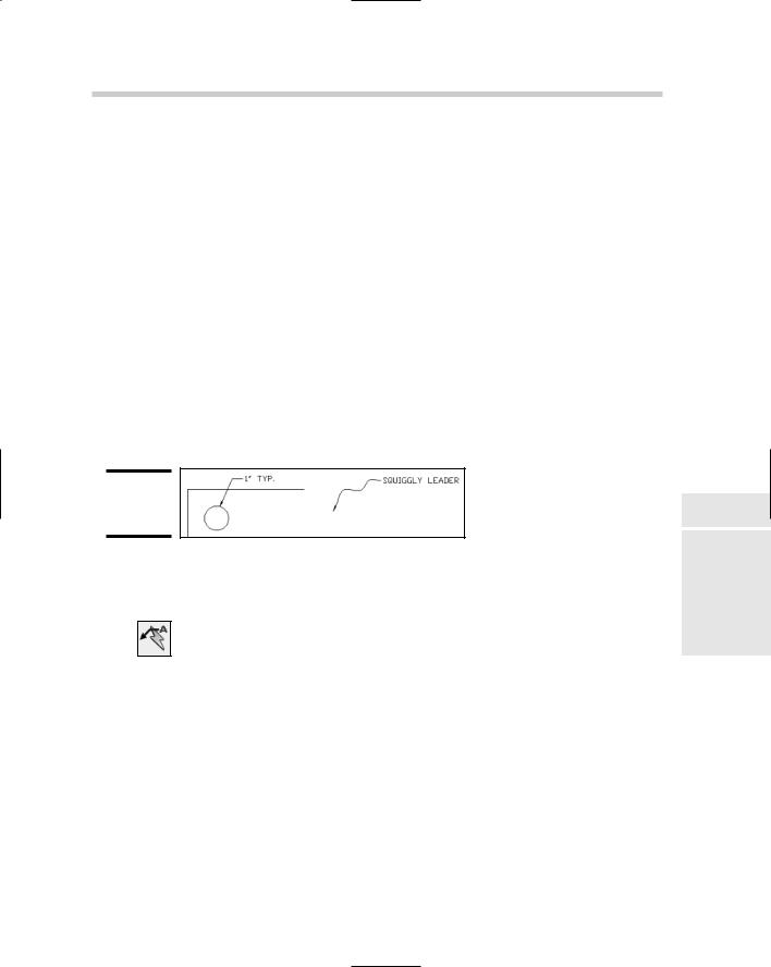
Leaders
Leaders are used to point to and call out features or draw attention to something in a design (see Figure 2-19). A leader typically has an arrowhead at one end pointing to something in the drawing, whereas the other end has text, an object, a block, or a tolerance object. The leader can contain any of the arrowheads that dimensions can, and the leader line can contain as many straight or spline segments that you want it to have.
Figure 2-19:
Examples of leaders.
Leaders are created using the QLEADER command. To start the QLEADER command, follow one of the methods outlined below:
Dimension menu: Choose Dimension Leader.
Dimension toolbar: Click the Quick Leader button on the Dimension toolbar.
Keyboard input: Type QLEADER and press Enter.
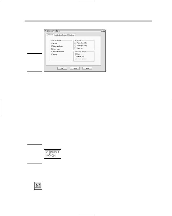
As soon as the QLEADER command is started, it allows you to start creating a leader right away by selecting points. The number of points that you
can pick are based on the settings of the QLEADER command. The Leader Settings dialog box (see Figure 2-20) is used to specify the options for the QLEADER command when creating a new leader. The leader line and arrowheads are created as a single object, but any text, block, object, or tolerance that is placed with the leader is treated as a single object.
Book III
Chapter 2
Dimensioning
238 Working with Geometric Tolerances
Figure 2-20:
The Leader Settings dialog box.
When using the QLEADER command, follow the prompts at the command line or the dynamic input tooltip. Leaders can be edited using grips, the proper editing command based on the type of object inserted with the leader, and the common modify commands. If you need additional help, reference the online Help system.
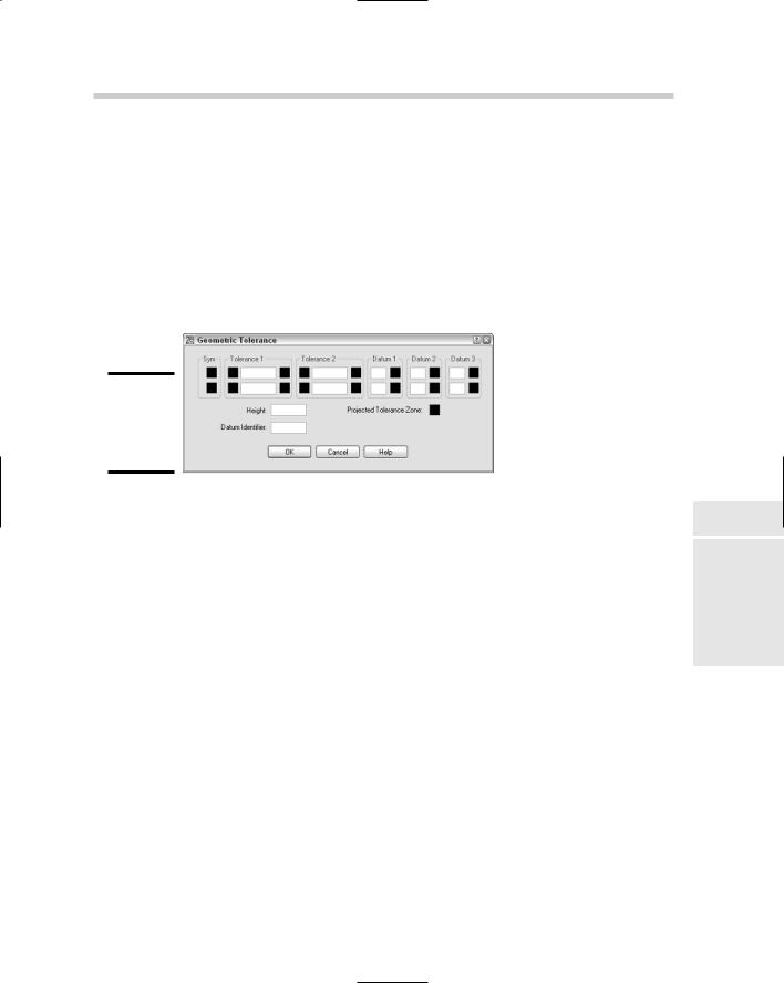
Working with Geometric Tolerances
Geometric tolerances allow you to create a series of what are called feature control frames. Feature control frames can contain symbols, tolerance values, datum references, and projected tolerance zone values (see Figure 2-21). Geometric tolerances are used for mechanical drawings and vary based on the standards that you need to follow, such as ANSI (American National Standards Institute), ISO (International Standards Organization), or JIS (Japanese Industrial Standards).
Figure 2-21:
The Geometric tolerance.
Geometric tolerances are created using the TOLERANCE command. To start the TOLERANCE command, follow one of the methods outlined below:
Dimension menu: Choose Dimension Tolerance.
Dimension toolbar: Click the Tolerance button on the Dimension toolbar.
Working with Geometric Tolerances 239
Keyboard input: Click TOLERANCE on the Dimension toolbar.
Command alias: Type TOL and press Enter.
When you start the TOLERANCE command, you are prompted for the insertion point of the geometric tolerance object and then the Geometric Tolerance dialog box (see Figure 2-22) is displayed. In the Geometric Tolerance dialog box you can specify the tolerances, datum references, symbols, and projected tolerance zone value. Geometric tolerances can be modified using grips, the DDEDIT command, and the common modifying commands. If you need help, reference the online Help system.
Figure 2-22:
The Geometric Tolerance dialog box.
Book III
Chapter 2
Dimensioning
240 Book III: Annotating Drawings
Chapter 3: Hatching
Your Drawings
In This Chapter
Adding hatch patterns and fills
Working with gradient fills
Editing hatch patterns and fills
In this chapter, you discover hatch patterns and fills and how to create and edit them. Hatch patterns and fills are used to communicate a design
concept and help improve the way a flat 2D drawing looks. AutoCAD and AutoCAD LT offer two different types of hatches: hatch patterns and solid fills. Hatch patterns are made up of line segments that are stored in pattern files, whereas solid fills are a single color and are not made up of line segments. AutoCAD offers an additional hatch type called gradient fills.
Gradient fills are similar to solid fills except they are a blend of one color with a tint, or two colors, to give the illusion of depth and realism to a 2D drawing. Hatching allows you to quickly add a visual representation of floor tiles, shingles, or shakes on a roof for an architectural drawing. For a mechanical drawing, you might use a hatch pattern that creates diagonal lines to represent the part of a model that is shown cut through for a section view.
Hatch objects are created by default as a single object and are associative like dimensions. Hatch objects are created associative to the objects that form the closed boundary in which the hatch object is created. Keeping a hatch object associative allows it to be automatically updated when the boundary changes. Hatch objects can also be created non-associative, which keeps the hatch object from being updated when the boundary changes. Hatch objects can be exploded if they are created with a hatch pattern other than a solid or gradient fill. Figure 3-1 shows a drawing that uses hatch patterns and fills to indicate the materials used for the exterior of a building.