
AutoCAD & AutoCAD LT All-In-One Desk Reference For Dummies (2006)
.pdf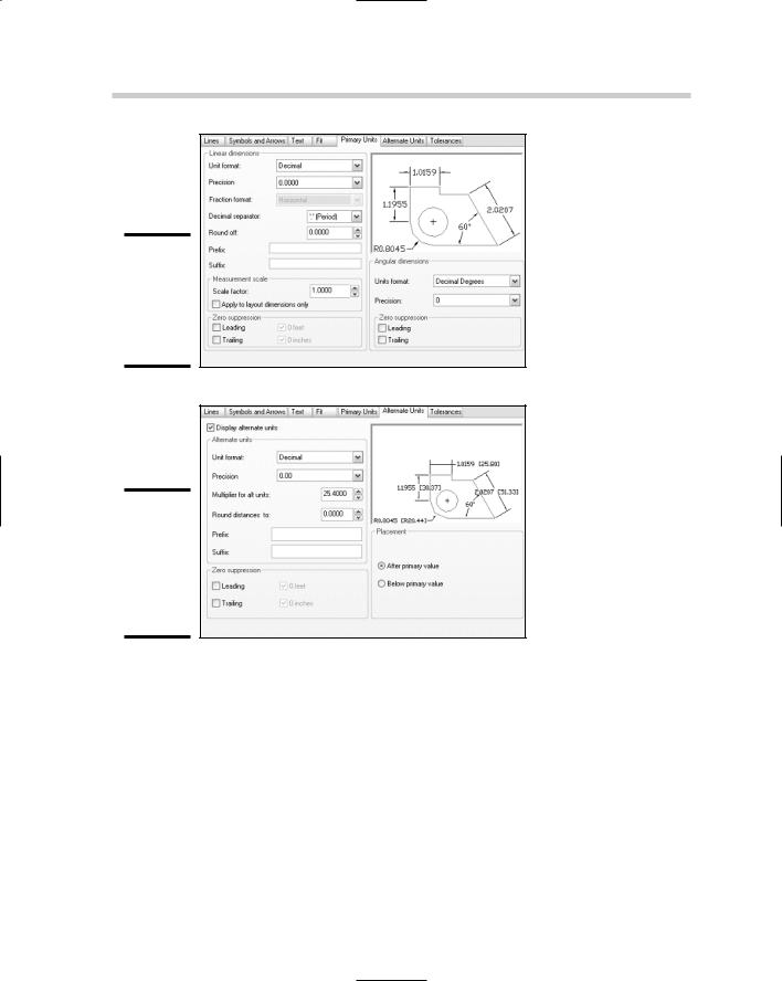
222 Using and Creating Dimension Styles
Figure 2-9:
The Primary Units tab of the New Dimension Style dialog box.
Figure 2-10:
The Alternate Units tab of the New Dimension Style dialog box.
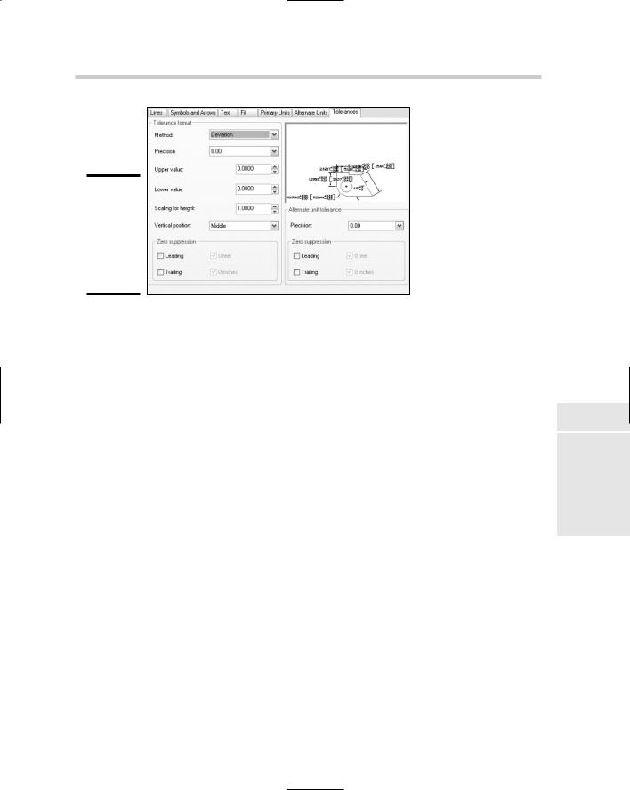
The Tolerances tab
The Tolerances tab (see Figure 2-11) allows you to define how tolerances appear as part of the dimension text. Dimension text tolerances are much different from the geometric tolerance object, which we talk about later in this chapter. On the Tolerances tab, you can specify the type of tolerance that is displayed with dimension text, the format of the tolerance including precision, upper, and lower limits, and how leading and trailing zeroes are suppressed. The settings affect both linear and angular measurement values for dimensions.
Using and Creating Dimension Styles 223
Figure 2-11:
The Tolerances tab of
the New
Dimension Style dialog box.
Dimension variables
AutoCAD and AutoCAD LT hide many of their complex workings from the user in the latest releases, but it has not always been this way. In earlier releases of AutoCAD, when dimensions were first introduced, you had to know a number of system variables that were specific to dimension styles. Even to this day, you can access the system variables that are specific to the current dimension style and make changes to them through script files as you are creating dimensions in a drawing. By changing the values of the dimension system variables in this way, you are creating an override for the current dimension style that is applied to each new dimension that is created in the drawing. You can get a list of the dimension system variables by doing the following:
1.At the command line or dynamic input tooltip, enter SETVAR and press Enter. The following prompt is displayed:
Enter variable name or [?]:
2.At the prompt, type ? and press Enter. The following prompt is displayed:
Enter variable(s) to list <*>:
3.At the prompt, type DIM* and press Enter.
The system variables that are specific to the current dimension style are displayed in the AutoCAD Text window or AutoCAD LT Text window.
4.Press Enter to continue listing additional system variables that are related to dimensions.
Book III
Chapter 2
Dimensioning

224 Using and Creating Dimension Styles
Keep pressing Enter until you see the dimension system variable that you want to change.
5.Press ESC to end the SETVAR command, and then type the dimension system variable’s name at the command line or dynamic input tooltip.
You are prompted for the new value.
6.Enter the new value and press Enter.
The value is updated accordingly.
If you need help with what values can be used with a dimension system variable, press F1 and the online Help for that system variable opens. This also works well for commands that are in progress and other system variables.
Setting a dimension style current
Dimension styles need to be set current in order to be used to create new dimensions. AutoCAD and AutoCAD LT allow you to set a dimension style current in several different ways. The two most common ways of setting a dimension style current are
Styles or Dimension toolbar: On the Styles or Dimension toolbar, select the dimension style that you want to set current from the Dimension Styles drop-down list.
Dimension Style Manager: Double-click the dimension style under the Styles list box to set it current, or select the dimension style from the Styles list box. Select Set Current from the right-click menu or click the Set Current button.
Modifying a dimension style
At times, you may find that a dimension style needs to be updated. This could be due to changes to the current CAD standards or even requirements that dimensions be provided with specific arrowheads or formatting for a client. You are already familiar with creating a dimension style, so you will find modifying one isn’t that much different.
Dimension styles are modified through the Dimension Style Manager dialog box. After the Dimension Style Manager dialog box is displayed, select the dimension style from the Styles list box and click the Modify button on the right side of the dialog box. The Modify Dimension Style dialog box is displayed, which is just like the New Dimension Style dialog box. Make the desired changes and then click OK to save the changes to the dimension style and to close the Modify Dimension Style dialog box.
Using and Creating Dimension Styles 225
Dimension style overrides
Dimension style overrides allow you to make small number of property changes to the current dimension style without creating a new dimension style altogether. Style overrides can cause some confusion in a drawing when creating new dimensions, unless you know that a style override is currently in use. To create a style override, you can change one of the dimension style variables, or click the Override button in the Dimension Style Manager dialog box and make the property changes that you want to be part of the style override.
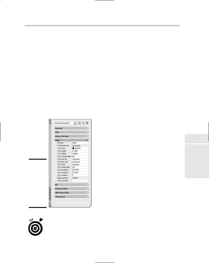
Only new dimensions that are created with a style override current are affected, so you could draw dimensions using different text fit options, if necessary, to accommodate some dimensions in a drawing. Overrides are best done at the individual dimension object level using the Properties palette. Selecting a dimension in a drawing allows you to override any property of a dimension object through the Properties palette (see Figure 2-12). This makes it easier to get the correct override that you might want to use instead of setting it through the Dimension Style Manager dialog box.
Figure 2-12:
The Properties palette allows you to override dimension style properties at the object level.
Dimension styles can be merged into the dimension style that they were created from by right-clicking over the text <Style Overrides> in the Dimension Style Manager dialog box, and selecting Save to Current Style. Only one dimension style override can exist in a drawing at a time, and switching to
Book III
Chapter 2
Dimensioning

226 Using and Creating Dimension Styles
another dimension style discards the style overrides unless they are saved to the dimension style.
Dimension substyles
Dimension substyles are different from editing dimension styles and style overrides because the substyle limits which properties you can edit based on the substyle that is created. Dimension substyles are created just like a new dimension style is, with the exception that you select one of the types of dimensions from the Use For drop-down list in the Create New Dimension Style dialog box, and you don’t need to specify a name for the dimension style. To modify a dimension substyle, select the substyle below the dimension style that the substyle is a part of and click the Modify button.
Renaming a dimension style
Only a dimension style can be renamed using the Dimension Style Manager dialog box or the Rename dialog box, but style overrides and substyles can’t be. To rename a dimension style using the Dimension Style Manager dialog box, select the dimension style from the Styles list box and press F2. The inplace editor appears and allows you to change the dimension style’s name. You can also right-click over the dimension style name and select Rename to replace the dimension style’s name.
Deleting a dimension style
Dimension styles, substyles, and style overrides can be deleted from a drawing through the Dimension Style Manager dialog box when they are not being used. To delete a dimension style, a substyle, or style overrides, right-click over the item in the Styles list box of the Dimension Style Manager dialog box and select Delete. When the AutoCAD or AutoCAD LT message is displayed, click Yes to confirm the deletion.
The PURGE command can be used to remove any unused dimension styles from a drawing.
Importing a dimension style
Dimension styles should be created in the drawing template that you start your new drawing with. At times, you may not want to place a dimension style in the drawing template that you use, but that doesn’t mean you have to go through and create the dimension style every time you need it either. You can use the DesignCenter palette to drag and drop dimension styles from one drawing to another. For more information on using DesignCenter, see Chapter 3 of Book VI.
Creating Dimensions 227
Creating Dimensions
AutoCAD and AutoCAD LT allow you to create many different types of dimensions to communicate overall design concepts: dimensions in the form of lengths and widths, hole locations and depths, and others. The important thing to note about dimensions is which ones you need and how to create them. This section covers the different kinds of dimensions that you can create in AutoCAD and AutoCAD LT.
Linear and aligned dimensions
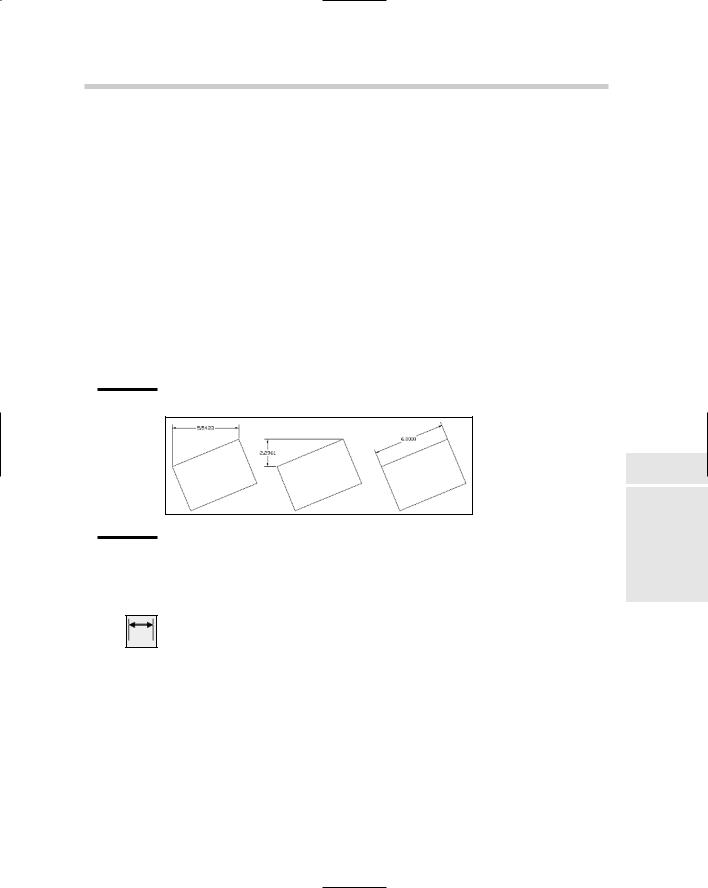
Linear dimensions are the most commonly used dimensions: They are used to measure an object or two points horizontally or vertically in a drawing. You use linear dimensions to dimension straight segments such as lines or polylines, the chord length of an arc, or the diameter of a circle, which can be created horizontally, vertically, or rotated (see Figure 2-13).
Figure 2-13:
Different linear dimensions that can be created with the
DIMLINEAR command.
Linear dimensions are created using the DIMLINEAR command. To start the DIMLINEAR command, follow one of the methods outlined below:
Dimension menu: Choose Dimension Linear.
Dimension toolbar: Click the Linear button on the Dimension toolbar.
Keyboard input: Type DIMLINEAR and press Enter.
Command alias: Type DLI and press Enter.
Aligned dimensions are similar to linear dimensions except they are not created orthogonally based on the origin points picked. The difference in the way aligned dimensions are created versus linear dimensions causes them to measure the actual distance between the origin points selected, instead of
Book III
Chapter 2
Dimensioning

228 Creating Dimensions
the horizontal or vertical distance. Aligned dimensions are created using the DIMALIGNED command, and its command prompts are for the most part identical to the DIMLINEAR command. To start the DIMALIGNED command, follow one of the methods outlined below:
Dimension menu: Choose Dimension Aligned.
Dimension toolbar: Click the Aligned button on the Dimension toolbar.
Keyboard input: Type DIMALIGNED and press Enter.
Command alias: Type DAL and press Enter.
The following procedure starts the DIMLINEAR command and explains how to create a linear dimension:
1.Use any of the four previously listed methods to initiate the DIMLINEAR command.
The DIMLINEAR command starts and this prompt is displayed:
Specify first extension line origin or <select object>:
2.At the prompt, pick a point for the first origin point of the dimension or press enter to select an object to dimension.
If you select a point, the prompt Specify second extension line origin: is displayed. If you press Enter, the prompt Select object to dimension: is displayed.
When specifying points for the origins of dimensions, use object snaps to make sure that the dimensions are created with the correct measurement.
3.At the Specify second extension line origin prompt, pick a point for the second origin point of the dimension. At the Select object to dimension prompt, select an object to dimension in the drawing.
The prompt Specify dimension line location or [Mtext/Text/ Angle/Horizontal/Vertical/Rotated]: is displayed.
4.At the prompt, pick a point to place the dimension or specify one of the command’s options.
The dimension is placed and the command ends. The options Mtext, Text, and Angle affect the value of the dimension text or how the dimension text is rotated. The options Horizontal, Vertical, and Rotated affect how the dimension is created in the drawing and the measurement value that is calculated.
Creating Dimensions 229
Baseline and continued dimensions
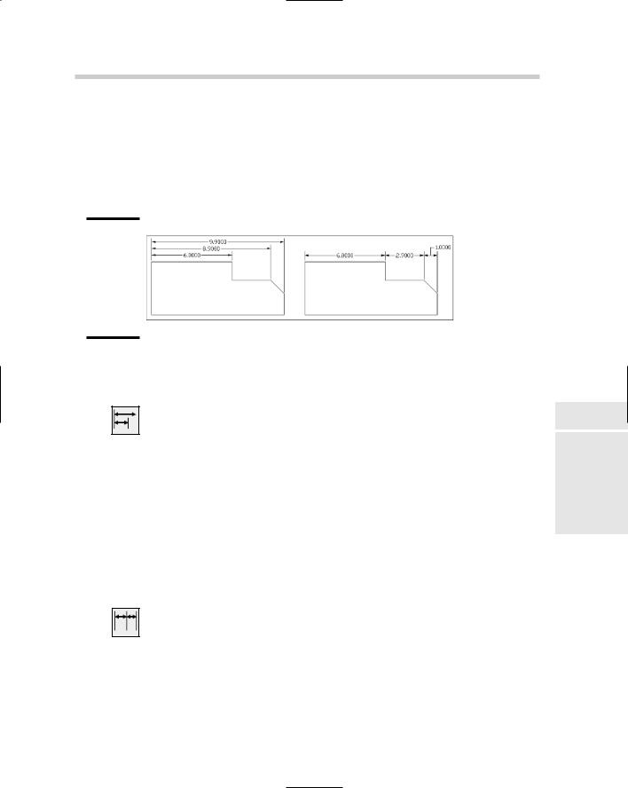
Baseline dimensions allow you to create a string of dimensions (see Figure 2-14) that continue from the first origin point of the previous linear, aligned, angular, or ordinate dimension. Typically, you place the first dimension and then follow it up by creating baseline dimensions, but you have the option of creating baseline dimensions by selecting an existing dimension in a drawing.
Figure 2-14:
Baseline and Continued dimensions based on a linear dimension.
Baseline dimensions |
Continued dimensions |
Baseline dimensions are created using the DIMBASELINE command. To start the DIMBASELINE command, follow one of the methods outlined below:
Dimension menu: Choose Dimension Baseline.
Dimension toolbar: Click the Baseline button on the Dimension toolbar.
Keyboard input: Type DIMBASELINE and press Enter.
Command alias: Type DBA and press Enter.
Continued dimensions allow you to create a string of dimensions that continue from the second origin point of the previous linear, aligned, angular, or ordinate dimension. As with baseline dimensions, you commonly place the first dimension and then follow it up by creating the continued dimensions, but you have the option of creating continued dimensions by selecting an existing dimension in a drawing. Continued dimensions are created using the DIMCONTINUE command, and its options are identical to the DIMBASELINE command. To start the DIMCONTINUE command, follow one of these methods:
Dimension menu: Choose Dimension Continue.
Dimension toolbar: Click the Continue button on the Dimension toolbar.
Keyboard input: Type DIMCONTINUE and press Enter.
Command alias: Type DCO and press Enter.
Book III
Chapter 2
Dimensioning
230 Creating Dimensions
The following procedure starts the DIMBASELINE command and explains how to create a baseline dimension:
1.Use any of the four methods just listed to initiate the DIMBASELINE command.
The DIMBASELINE command starts and the prompt Specify a second extension line origin or [Undo/Select] <Select>: is displayed, or the prompt Select base dimension: is displayed.
2.At the Specify a second extension line origin or [Undo/ Select] <Select> prompt, pick a point for the second origin point of the dimension or press enter to select an object to dimension.
If you select a point, the prompt Specify a second extension line origin or [Undo/Select] <Select>: is redisplayed.
3.At the prompt, press Enter twice to exit the command or pick another point to place another baseline dimension.
After you press Enter once, the prompt Select base dimension: is displayed, which allows you to select another dimension to start creating baseline dimensions from.
Angular dimensions
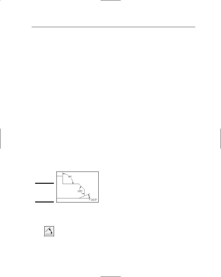
Angular dimensions (see Figure 2-15) allow you to show the angular measurement in a drawing. The angular measurement might be based on the end points of an arc, the angular relationship between two straight segments, the center of a circle and another angle, or two vertexes that define an angle.
Figure 2-15:
Angular dimensions.
Angular dimensions are created using the DIMANGLUAR command. To start the DIMANGLUAR command, use one of these methods:
Dimension menu: Choose Dimension Angular.
Dimension toolbar: Click the Angular button on the Dimension toolbar.
Creating Dimensions 231
Keyboard input: Type DIMANGULAR and press Enter.
Command alias: Type DAN and press Enter.
The following procedure starts the DIMANGULAR command and explains how to create an angular dimension based on two lines:
1.Use any of the four methods just listed to initiate the DIMANGULAR command.
The DIMANGULAR command starts and the prompt Select arc, circle, line, or <specify vertex>: is displayed.
2.At the prompt, select a line segment.
The prompt Select second line: is displayed.
3.At the prompt, select another line segment.
The prompt Specify dimension arc line location or [Mtext/ Text/Angle]: is displayed.
4.At the prompt, pick a point to place the dimension or specify one of the command’s options.
The dimension is placed and the command ends.
Arc length dimensions
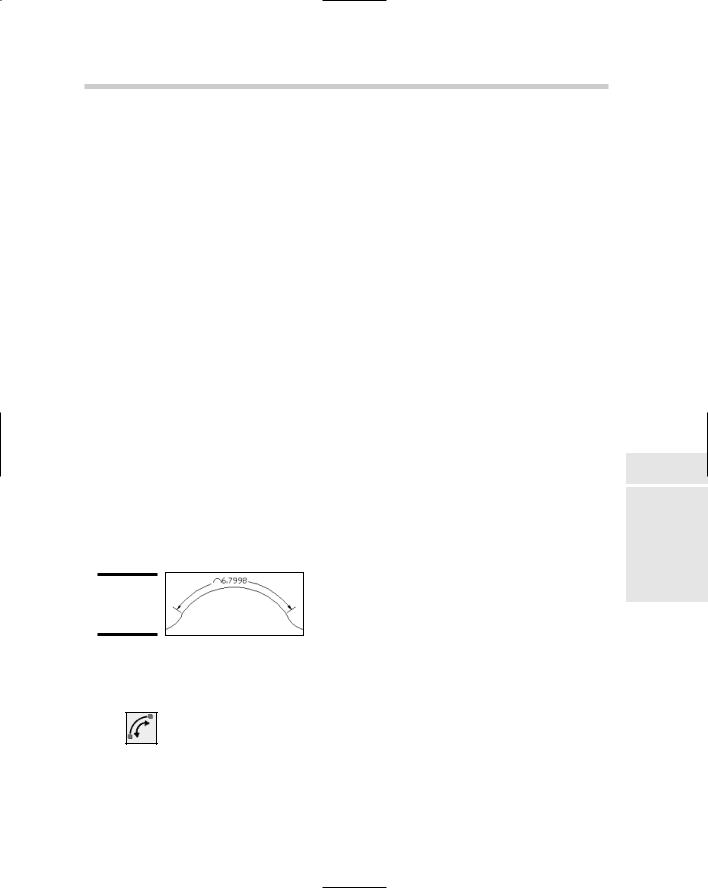
Arc length dimensions (see Figure 2-16) are similar to angular dimensions, except instead of measuring an angle, they measure the length of an arc or an arc segment of a polyline. Based on how an arc needs to dimensioned, you might use the arc length dimension over an angular or linear dimension.
Figure 2-16:
Arc length dimensions.
Arc length dimensions are created using the DIMARC command. To start the DIMARC command, follow one of the methods outlined below:
Dimension menu: Choose Dimension Arc Length.
Dimension toolbar: Click the Arc Length button on the Dimension toolbar.
Book III
Chapter 2
Dimensioning
