

AutoCAD & AutoCAD LT All-In-One Desk Reference For Dummies (2006)
.pdf202 Working with Multiline Text
Finally, a font’s full character set (that is, non alphanumeric symbols) is readily accessible in multiline text. Single-line text offers just a very few special characters that have to be entered with special codes.
Hopefully the advantages of multiline text encourage you to hang in there with it. The final bit of advice is this: If you only learn one kind of text in AutoCAD, make it multiline text!
You create both single-line and multiline text in an in-place text editor. Inplace means the text you create in the editor is going to appear in the drawing in exactly that place at exactly that size when you finish creating the text and close the editor. For single-line text, the in-place editor is simply a Windows-style text box, but for multiline text, it’s much more elaborate, consisting of the two components shown in Figure 1-6:
Text formatting toolbar: The toolbar contains a multitude of drop-down lists and tool buttons that would do a word processor proud. Set justification, color, or style; add symbols or fields; or fine-tune character or line spacing.
Bounding box with ruler: The text you type appears within the bounding box. You can set margin and tab stops in the ruler by dragging the pointers, just like in a word processor. If you don’t see a ruler atop the bounding box, click the Ruler button in the top row of the Text Formatting toolbar.
Figure 1-6:
The multiline text editor.
Creating Multiline Text 203
Creating Multiline Text
The following steps show you how to add a paragraph multiline text to a drawing:
1. Choose Draw Text Multiline Text.
The standard crosshairs change to a plain crosshairs and ghosted text in the current style and height. AutoCAD displays the current text style name and height at the command line and prompts as follows:
Command: _mtext Current text style: “MyNewStandard”
Text height: 2.6654
Specify first corner:
2. Pick the first corner of the bounding box.
The default multiline text justification is Top Left, so the first point you pick will be the upper-left corner of the text object. AutoCAD displays this prompt:
Specify opposite corner or [Height/Justify/Line spacing/Rotation/Style/Width]:
3.Enter a command option or pick the second corner.
Enter the uppercased letter of the option to change text height, justification, line spacing, rotation, style, or the overall width of the text box. To retain all the default settings, pick the diagonally opposite corner of the text box. The command prompt disappears, and the in-place text editor displays the Text Formatting toolbar and bounding box.
The bounding box sets only the width of the multiline text object. It doesn’t matter how tall you make the box — it will expand as necessary to include all the text you enter.
4.Type your text.
The text you type flows across the bounding box. When it reaches the opposite side, it wraps automatically to the next line, just like your favorite word processor.
Formatting options
The two rows of buttons and drop-down lists in the Text Formatting toolbar (refer to Figure 1-6) enable you to perform many of the functions of a fullyfeatured word processor. You can change the style, font, height, and any number of other properties of your multiline text object. See the online Help system for a full description of each formatting option — on the Contents tab, choose Command Reference MTEXT In-Place Text Editor.
Book III
Chapter 1
When Text:Won’t Just
PicturesDo
204 Creating Multiline Text
A multiline text object can be created using only one text style. If you type some text, change the style and type some more, the entire multiline text object changes to the new style. You can get the effect of different styles by highlighting some text and changing the font, height, color, and so on.
Numbered and bulleted lists
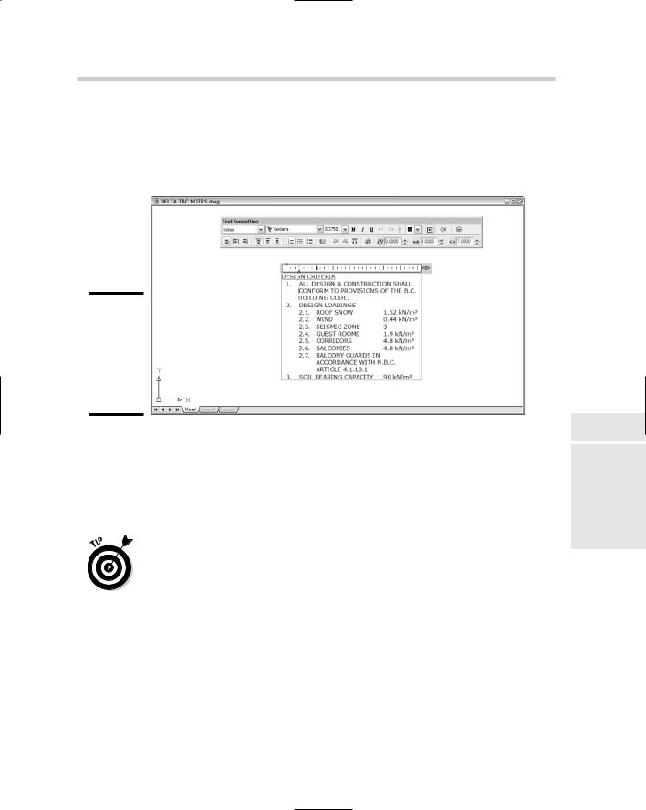
Another advantage of multiline text is that it supports bulleted and numbered lists. This feature is especially useful for creating general drawing notes, as shown in Figure 1-7. AutoCAD automates the process of creating numbered lists almost completely. Here’s how:
1.Follow Steps 1 through 3 in the previous section, “Creating Multiline Text.”
2.Type a title; for example, DESIGN CRITERIA.
If you’d like to have your title underlined, click Underline on the Text Formatting toolbar before you type the title, and then click Underline again to turn it off.
3.Press Enter to go to the next line and Enter again.
Leave a little more space between the title and the body of the text.
4.Right-click inside the text editing window and choose Bullets and Lists Numbered Allow Auto-List Use Tab Delimiter Only
Allow Bullets and Lists.
The number 1 followed by a period appears on the current line, and the cursor jumps to the tab stop visible in the ruler at the top of the text editor’s bounding box.
Numbered places numerals followed by periods in front of items in a list. Lettered places uppercase or lowercase letters followed by periods in front of list items. (Bulleted places bullet characters in front of list items.) Auto-list enables automatic numbering — each time you press Enter to move to a new line, its number increments. Use Tab Delimiter Only means you must press the Tab key to move to the tab stop.
5.Type the text corresponding to the current number or bullet.
As AutoCAD wraps the text, the second and subsequent lines align with the tab stop — that is, the text is automatically indented.
6.Press Enter at the end of the paragraph to move to the next line.
Just like creating numbered lists in your favorite word processor, AutoCAD automatically inserts the next number at the beginning of the new paragraph, with everything perfectly aligned, as shown in Figure 1-7.
Creating Multiline Text 205
7.Type the text corresponding to the next number or bullet, and then press Enter at the end of the paragraph to move to the next line.
8.Repeat Steps 5 through 7 for each subsequent numbered or bulleted item.
Figure 1-7:
Tabs, indents, and automatic numbering set to create numbered lists.
Fields, masks, and other multiline text delights
We haven’t exhausted the features of the multiline text editor yet, and two especially useful ones are fields and background masks. The multiline text editor also offers a panoply of little functions and utilities that come in handy from time to time.
The convention in drafting is that text in a drawing is uppercased at all times. One way to avoid having to keep the Shift key pressed down is to use the Caps Lock key. But when you finish your texting and want to log in to your network, if you forget to turn off Caps Lock, you get an error message. The multiline text editor has a great solution for you. Right-click inside the editor and choose AutoCAPS. Everything you type in the text editor is uppercased, without benefit of Caps Lock.
Fields
Book III
Chapter 1
When Text:Won’t Just
PicturesDo
Fields are placeholders for changeable data that updates automatically — for example, the author of a drawing and when it was created, last saved, or plotted. This data comes from drawing properties, or some system variables,
206 Creating Multiline Text
or a sheet set (neither fields nor sheet sets are available in AutoCAD LT). To display the Field dialog box (see Figure 1-8), right-click inside the multiline text editor and choose Insert Field. For more information on inserting and updating fields, refer to the online Help system.
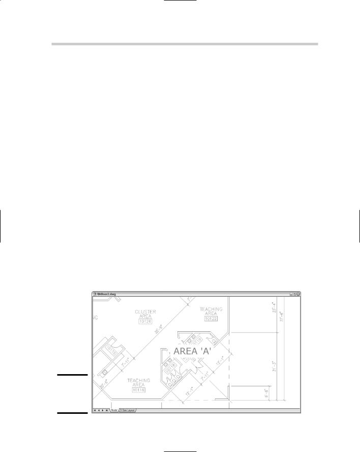
Background masks
Sometimes you just have to place a note on top of drawing objects, and invariably, it looks bad. If your note is multiline text, you can mask the background drawing data so the text displays clearly as follows:
1.In a drawing containing some graphic objects, add some multiline text on top of the drawn objects.
2.Right-click inside the text editor and choose Background Mask.
The Background Mask dialog box appears.
3.Check Use Background Mask to enable the feature.
The remaining dialog box options become accessible.
4.Set a Border Offset factor.
This value, which must be between 1 and 5, controls the distance beyond the text object that the mask extends. When set to 1, the mask is tight to the text object.
5.In the Fill Color area, either check Use Drawing Background Color or click the drop-down list to select a color for the mask.
If you don’t want bright red rectangles all over your drawing, make sure you check the Use Drawing Background color box.
Figure 1-8:
Masking the background of your text.

Editing Text 207
Editing Text
After you’ve created either single-line or multiline text, editing it is a pretty straightforward exercise. As you might expect, there are two different editors for the two different types of text. So how do you know which editor to use? Easy — AutoCAD chooses for you if you double-click the text.
Editing single-line text
We’ve already pointed out all the formatting options available in multiline text, and if those are what you need, it’s multiline text for you. Your editing options are fewer with single-line text, but for simple text, they should be more than ample.
Both types of text use an in-place text editor, where the text appears inside an edit box at the size and location it will appear in the drawing. Simply double-click a string of single-line text to display it in the in-place editor. All you can change here is the value of the text itself. If you need to change other properties such as style, justification, or height, select the text and make changes in the Properties palette.
If you’re an old hand at AutoCAD and you absolutely hate the new single-line text editor, you can restore the pre-AutoCAD 2006 Edit Text dialog box by setting the system variable DTEXTED to 1.
Editing multiline text
Double-clicking a multiline text object also opens its in-place editor, but as you’ve already seen, it’s an editor with a lot more bells and whistles. We’ve covered most of the options in the earlier sections on creating multiline text. To change all or parts of the text, select as you would in a word processor and apply your changes. Then click OK in the Text Formatting toolbar, or simply click outside the in-place editor.
Single-line text isn’t allowed to have anything that paragraph text doesn’t also have, so there is also an MTEXTED system variable that lets you revert to the previous editor. To do so, type MTEXTED and press Enter; then type OldEditor and press Enter. The old editor still has the same toolbar and ruler, but the bounding box does not display the selected text at its actual size or location.
Fiddling with text can be a tedious task, and lots of little-known commands and functions let you do your tweaking more efficiently. Two such commands let you adjust text height and justification in different ways:
SCALETEXT: Say you have a whole bunch of annotations in your drawing, and you want to reduce the size of all of them. The SCALE command
Book III
Chapter 1
When Text:Won’t Just
PicturesDo

208 Turning the Tables
would require a lot of selecting and moving, but SCALETEXT scales each text object about its own insertion point, so it stays where it ought to.
JUSTIFYTEXT: If you change the justification of text in the Properties palette or the multiline text editor, the insertion point stays put and the text moves. JUSTIFYTEXT lets you change the justification by keeping the position of the text where it is and moving the insertion point.
Turning the Tables
Table objects were introduced in AutoCAD 2005. Prior to that, if you needed to add a table — say a bill of materials, or a door schedule, or a drawing list, or any kind of data that can usefully be presented in rows and columns — you were in for several hours’ work, drawing lines, adding text, moving lines, and lining everything up at the end. AutoCAD’s tables can start at the top and flow downwards, as they would in most of the examples mentioned. They can also be anchored at the bottom of a sheet and flow upwards, which is the typical fashion for things like revision blocks. Tables can contain regular text, attributes, or fields.
Setting the table with styles
Tables, like text and dimensions, are defined according to styles. Every drawing has at least one table style waiting to be called on; the default templates contain a table style called (what else?) Standard. The following steps explain how to create a table style:
1.Choose Format Table Style.
The Table Style dialog box appears, showing on the left a list of all table styles defined in the current drawing, and on the right a preview of the current style settings. You can select existing table styles to set current, modify, or delete; however, you can’t delete the Standard style.
2.Click New to create a new table style.
The Create New Table Style dialog box appears.
3.Enter a name for the new style; for example, Door Schedule.
If you have more than one style defined, you can use the drop-down list to select an existing table style as the prototype for the new style.
4.Click Continue.
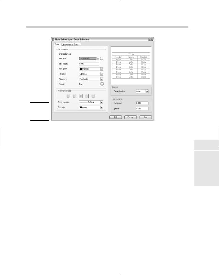
The New Table Style: Door Schedule dialog box opens, again with a preview of the current settings at the right (see Figure 1-9).
Turning the Tables 209
Figure 1-9:
Setting the table.
A table style has up to three parts: the data, the column heads, and the title. Each of the three has a tabbed panel at the left side of the dialog box. The panels are identical, except there are check boxes in the latter two to turn off their display. In other words, your table can contain the data only; the data and column heads; the data and a table title; or the data, column heads, and a title.
5.In the Data tab, configure the text options and fill color. To change the data format, click the button with the ellipses alongside the Format entry.
The Preview updates as you change settings in the left panel.
6.Repeat Step 5 for the Column Headings and Title tabs, or clear the check boxes to turn off display of headings and title.
7.In the General area, specify whether the table direction should be Down (the default) or Up.
8.Modify the values in the Cell margins boxes to increase or decrease the space between the table text and the lines.
You don’t specify row heights or column widths in the table style; specify these values when you create a table object.
9.Click OK to close the New Table Style dialog box.
AutoCAD returns to the Table Style dialog box.
10.Click Set Current, and then click Close.
Book III
Chapter 1
When Text:Won’t Just
PicturesDo
210 Turning the Tables
Creating and editing tables
After the table style is created, use the TABLE command to add a table object to your drawing. The following steps show how:
1.Choose Draw Table.
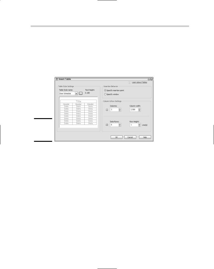
The Insert Table dialog box appears (see Figure 1-10).
Figure 1-10:
Rows and columns for a table.
2.Select a table style from the Table Style Name drop-down list or click Table Style dialog to create a new table style.
The Table Style Settings area displays the current text height.
3.In the Insertion Behavior area, choose Specify Insertion Point or Specify Window.
Specify Insertion Point is the preferable option, as it maintains the height and width settings you set in the table and text styles. Choosing Specify Window squeezes or stretches the table into the rectangular area you define. This option also disables the Data Rows value, which generates as many rows as fit in the window you pick; however, you can check the radio button to enable it again.
4.Specify the number of columns and data rows.
“Data rows” excludes the rows for the title and column headings.
5.Adjust the column width and row height as required.
One or the other pair of these options is grayed out if you choose Specify Window in Step 3.
Turning the Tables 211
6.Click OK.
The empty table is placed in the drawing. The Text Formatting toolbar appears, and the first column cell is highlighted, ready for text input.
7.Enter the table title, column headings, and data.
It’s now a matter of simply filling in the spaces. Now imagine creating a table like that with the TEXT and LINE commands!
If you just want to create the table frame and come back to input the text later, just click outside the highlighted cell.
To add table data, or to edit what’s already there, double-click inside the table cell.
Combine tables and fields to automatically populate a drawing title block or revision block. Field data updates automatically when the data source changes.
Table cells can also contain blocks, so you could create a drawing legend with graphic symbols in one column and a description of what they stand for in another column.
Book III
Chapter 1
When Text:Won’t Just
PicturesDo