

AutoCAD & AutoCAD LT All-In-One Desk Reference For Dummies (2006)
.pdf152 AutoCAD’s Editing Commands
Table 2-2 (continued)
Icon |
|
Toolbar |
Menu |
Command |
Alias |
Function |
|
|
|
|
(Modify U/N) |
(Modify U/N) |
Name |
|
|
|
|
|
|
|
|
|
|
|
|
|
Fillet |
Fillet |
FILLET |
F |
Apply rounded |
|
|
|
|||||
|
|
|
|
|
|
|
corner to inter- |
|
|
|
|
|
|
|
secting objects. |
|
|
|
|
|
|
|
|
|
|
|
|
|
|
|
|
--- |
--- |
--- |
GROUP |
G |
Create object |
||
|
|
|
|
|
|
|
groupings. |
|
|
|
|
|
|
|
|
|
|
|
Join |
Join |
JOIN |
J |
Connect selected |
|
|
|
|||||
|
|
|
|
|
|
|
discontinuous |
|
|
|
|
|
|
|
objects. |
|
|
|
|
|
|
|
|
|
|
|
|
|
|
|
|
--- |
--- |
Lengthen |
LENGTHEN |
LEN |
Change length of |
||
|
|
|
|
|
|
|
open objects. |
|
|
|
|
|
|
|
|
|
|
|
Standard, Match |
Match |
MATCHPROP |
MA |
Apply properties |
|
|
|
|||||
|
|
|
Properties |
Properties |
|
|
of one object to |
|
|
|
|
|
|
|
other objects. |
|
|
|
|
|
|
|
|
|
|
|
Mirror |
Mirror |
MIRROR |
MI |
Create mirrored |
|
|
|
|||||
|
|
|
|
|
|
|
original or copy. |
|
|
|
|
|
|
|
|
|
|
|
|
|
|
|
|
|
|
|
Move |
Move |
MOVE |
M |
Relocate |
|
|
|
|||||
|
|
|
|
|
|
|
selected objects. |
|
|
|
|
|
|
|
|
|
|
|
|
|
|
|
|
|
|
|
Offset |
Offset |
OFFSET |
O |
Create duplicate |
|
|
|
|||||
|
|
|
|
|
|
|
object specified |
|
|
|
|
|
|
|
distance. |
|
|
|
|
|
|
|
|
--- |
--- |
--- |
OOPS |
--- |
Unerase the last |
||
|
|
|
|
|
|
|
erased objects. |
|
|
|
Standard, Paste |
Edit Paste |
PASTECLIP |
--- |
Paste objects |
|
|
|
|||||
|
|
|
|
|
|
|
from Windows |
|
|
|
|
|
|
|
Clipboard. |
|
|
|
|
|
|
|
|
|
|
|
|
|
|
|
|
|
|
|
Modify II, |
Object |
PEDIT |
PE |
Modify geometric |
|
|
|
|||||
|
|
|
Edit Polyline |
Polyline |
|
|
properties of |
|
|
|
|
|
|
|
selected polyline. |
|
|
|
|
|
|
|
|
|
|
|
|
|
|
|
|
|
|
|
Standard, |
Properties |
PROPERTIES |
PR |
List and change |
|
|
|
|||||
|
|
|
Properties |
|
|
|
object properties. |
|
|
|
|
|
|
|
|
|
|
|
|
|
|
|
|
|
|
|
Standard, Redo |
Edit Redo |
REDO |
--- |
Reverse the |
|
|
|
|||||
|
|
|
|
|
|
|
last Undo. |
|
|
|
|
|
|
|
|
|
|
|
|
|
|
|
|
|
|
|
Rotate |
Rotate |
ROTATE |
RO |
Rotate selected |
|
|
||||||
|
|
|
|
|
|
|
object around |
|
|
|
|
|
|
|
base point. |
|
|
|
|
|
|
|
|
|
|
|
|
|
|
|
|
|
|
|
Scale |
Scale |
SCALE |
SC |
Resize objects |
|
|
||||||
|
|
|
|
|
|
|
from base point |
|
|
|
|
|
|
|
by a factor. |
|
|
|
|
|
|
|
|
AutoCAD’s Editing Commands 153
Icon |
Toolbar |
Menu |
Command |
Alias |
Function |
|||
|
|
|
|
(Modify U/N) |
(Modify U/N) |
Name |
|
|
|
|
|
|
|
|
|
|
|
|
|
|
|
Modify II, |
Object Spline |
SPLINEDIT |
SPE |
Modify geometric |
|
|
|
|
|||||
|
|
|
|
Edit Spline |
|
|
|
properties of |
|
|
|
|
|
|
|
|
selected spline. |
|
|
|
|
|
|
|
|
|
|
|
|
|
|
|
|
|
|
|
|
|
|
Stretch |
Stretch |
STRETCH |
S |
Resize objects by |
|
|
|
|
|||||
|
|
|
|
|
|
|
|
dragging them. |
|
|
|
|
|
|
|
|
|
|
|
|
|
|
|
|
|
|
|
|
|
|
Trim |
Trim |
TRIM |
TR |
Shorten object by |
|
|
|
|
|||||
|
|
|
|
|
|
|
|
cutting with other |
|
|
|
|
|
|
|
|
selected object. |
|
|
|
|
|
|
|
|
|
|
|
|
|
Standard, Undo |
Edit Undo |
U |
|
Reverse the last |
|
|
|
|
|
||||
|
|
|
|
|
|
|
|
single action. |
|
|
|
|
|
|
|
|
|
|
|
|
|
|
|
|
|
|
|
|
|
|
--- |
--- |
UNDO |
--- |
Reverse a selec- |
|
|
|
|
|||||
|
|
|
|
|
|
|
|
table series of |
|
|
|
|
|
|
|
|
actions. |
|
|
|
|
|
|
|
|
|
|
|
|
|
|
|
|
|
|
--- |
|
|
--- |
--- |
XPLODE |
XP |
Break complex |
|
|
|
|
|
|
|
|
|
objects into |
|
|
|
|
|
|
|
|
separate pieces |
|
|
|
|
|
|
|
|
specifying |
|
|
|
|
|
|
|
|
properties after |
|
|
|
|
|
|
|
|
exploding. |
Removing stuff
Everybody makes mistakes, and now it’s time to clear away the evidence. We present the simplest-to-use of all of AutoCAD’s editing commands: ERASE. We hope it’s not your most frequently used command, but it doesn’t really matter whether it is or not — you’re not going to rub a hole in your screen by erasing AutoCAD objects.
Here are some ways to erase stuff from your drawing:
Choose Modify Erase, select the undesirables, and then press Enter.
Choose Edit Delete, select the undesirables, and then press Enter.
Click the Erase tool in the Modify toolbar, select your objects, and then press Enter.
Select the unwanted objects, choose Modify Erase, or Edit Delete, or click Erase in the Modify toolbar.
Select the mistakes and then press Delete.
Select the unwanted objects, right-click, and select Erase.
Book II
Chapter 2
Objects Modifying
154 AutoCAD’s Editing Commands
Relocating and replicating
Most commands require more direction than simply selecting objects and clicking a tool button. The first set of commands we look at enables you to relocate and duplicate already existing drawing objects.
MOVE
Moving objects requires three sets of input: the objects you want to move, a point to move them from, and another point to move them to.
Using noun-verb editing for simple commands like MOVE and COPY saves keystrokes. You don’t want to overwork those pinkies, do you?
The following steps explain how to move objects using noun-verb editing:
1.Select a single object, or use one of the multiple selection methods described in the section “Selecting Multiple Objects” to select several objects.
AutoCAD highlights the objects and displays their grips. Don’t worry about the grips (all those blue boxes and wedges) — we discuss them near the end of the chapter.
2.Click the Move button on the Modify toolbar, or choose Modify Move, or type M to start the MOVE command.
AutoCAD prompts:
Command: _move 4 found
Specify base point or [Displacement] <Displacement>:
AutoCAD shows you the number of objects that are going to be moved, and then tells you what to do next — it wants you to specify a base point (“take these things from here”).
3.Pick a point on screen as the base point.
Sometimes you should pick a precise point for the base point, but if you’re only moving or copying something a relative distance, it really doesn’t matter where you pick. AutoCAD prompts:
Specify second point or
<use first point as displacement>:
4.Pick a second point or enter coordinates for the destination of the selected objects.
Remember, “second point” means “put it here.” AutoCAD moves the objects and returns to the command line.
AutoCAD’s Editing Commands 155
Even the simplest commands can throw you for a loop. You may get unexpected results if you press Enter in response to the Specify Second Point prompt. Pressing Enter tells AutoCAD to look at the coordinates of the first point and use those values as the displacement for the second point. We can pretty well guarantee this is not what you want.
COPY
When you use verb-noun editing, editing in AutoCAD is much more obviously a two-step process: you select the objects, press Enter, and carry on with the command. This is a good time to show you the difference, since the MOVE and COPY commands are pretty much the same.
Choosing Modify Copy runs the COPY command, which you use for duplicating existing objects within a drawing. Choosing Edit Copy runs the Windows Copy-to-the-Clipboard command, which AutoCAD calls COPYCLIP. Use COPYCLIP to copy objects from one drawing to another. Don’t confuse the two.
Use the following steps to copy some objects using the COPY command and verb-noun editing.
1.Click the Copy button on the Modify toolbar, or choose Modify Copy, or type CO to start the Copy command.
AutoCAD prompts:
COPY
Select objects:
2. Select the objects to be copied using any object selection method.
If you choose a window or crossing, AutoCAD prompts:
Specify opposite corner: 4 found
Select objects:
3.Press Enter when you’re finished selecting objects to copy.
The first prompts for COPY are exactly the same as for MOVE. What’s different this time around is that we’re copying using verb-noun selection, and we moved using noun-verb mode. After you press Enter to finish selecting, AutoCAD prompts:
Specify base point or [Displacement] <Displacement>:
4.Pick a point on-screen as the base point.
Again, use an object snap or other precision aid if you need to. If you’re simply copying objects relative to their current location, it doesn’t
Book II
Chapter 2
Objects Modifying
156 AutoCAD’s Editing Commands
matter where you pick. Once you’ve picked the first point, AutoCAD prompts:
Specify second point or
<use first point as displacement>:
5.Pick a second point or enter coordinates for the destination of the selected objects.
You can enter relative coordinates, or use Direct Distance Entry (see Chapter 6) or any precision method (where appropriate), or eyeball a point. For example, typing @2.85<0 makes a copy of the selected objects 2.85 units to the right of the originals.
AutoCAD prompts:
Specify second point or
<use first point as displacement>: @2.85<0 Specify second point or [Exit/Undo] <Exit>:
6.Continue making additional copies or exit the command.
By default, AutoCAD will continue offering to make copies until you tell it to stop. You can press Enter, the space bar, or the Esc key, or you can type E to exit the command.
MIRROR
MIRROR can create a single mirrored version of selected objects, or it can create a mirrored copy. Instead of picking a base and second point as you do with MOVE and COPY, with MIRROR you pick two points that are the end of an imaginary mirror. The selected object is “reflected” on the other side of the mirror line. The final MIRROR prompt asks if you want to retain or delete the original.
The following steps demonstrate the MIRROR command in verb-noun mode.
1.Click the Mirror button on the Modify toolbar, or choose Modify Mirror, or type MI to start the MIRROR command.
AutoCAD does its usual “Select objects” thing. By now you know the ropes — select some objects and press Enter. AutoCAD prompts:
Select objects: Specify opposite corner: 4 found Select objects: Specify first point of mirror line:
If it doesn’t matter where your objects get mirrored to, just pick a random point on-screen. Do the same for the second point. More often than not, though, it does matter. If that’s the case, make use of some of the precision drafting aids we discussed in Book I. In this example,

AutoCAD’s Editing Commands 157
the selected objects need to be mirrored precisely about the middle of a rectangle.
2.Hold down the Shift key and right-click to display the object snap shortcut menu. Choose Midpoint and pick a horizontal edge of the rectangle when you see the triangular object snap marker.
AutoCAD prompts:
Specify second point of mirror line:
3.Hold the Shift key and click a second point directly above or below the first point.
You need to be precise for your second point, too. Holding Shift invokes a temporary Ortho mode, when you move the crosshairs they will lock onto horizontal or vertical direction and remain that way until you release the Shift key (see Figure 2-4). AutoCAD prompts:
Erase source objects? [Yes/No] <N>:
4. Type Y or N to erase or retain the source objects.
Figure 2-4:
Mirroring objects precisely.
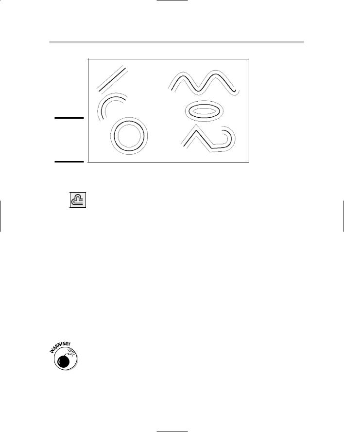
OFFSET
OFFSET, like COPY, makes duplicates of selected objects, but it’s more rigorous in where it lets you put those duplicates. It also doesn’t make exact copies; different object types offset in different ways. Figure 2-5 shows the results of offsetting different entity types. You can OFFSET lines, arcs, circles, splines, ellipses, and polylines.
Book II
Chapter 2
Objects Modifying
158 AutoCAD’s Editing Commands
Figure 2-5:
Offsetting different object types.
The following steps explain how to use OFFSET in verb-noun editing mode.
1.Click Offset on the Modify toolbar, or choose Modify Offset, or type O to start the OFFSET command.
AutoCAD prompts
Current settings: Erase source=No Layer=Source OFFSETGAPTYPE=0
Specify offset distance or [Through/Erase/Layer] <Through>:
2.Optionally, type E to erase the source object, or type L to change
the new object’s layer from the same layer as the source object to the current layer.
When offsetting objects, you can either specify an offset distance, or pick a Through point on-screen. Logically enough, choosing Through point offsets the object through the point you pick. The first time you run OFFSET in a drawing, the default value is <Through>.
3.Press Enter to use the Through point option.
AutoCAD prompts:
Select object to offset or [Exit/Undo] <Exit>:
If you simply pick a point, without pressing Enter to confirm the <Through> option, AutoCAD assumes you really want to enter an offset distance, will prompt you for a second point, and use the distance between the two points as the offset distance value.

AutoCAD’s Editing Commands 159
4. Select a single object to offset.
You can specify only one object at a time; that is, you can’t select a group of wall lines and offset them all in the same step. If you specified Through, AutoCAD prompts:
Specify through point or [Exit/Multiple/Undo] <Exit>:
For precise locations, use object snaps when picking through points. AutoCAD creates a new version of the selected object through the point you picked, and continues prompting for additional offsets and through points.
5. When you finish offsetting, press Enter to return to the command line.
If you enter a distance, you need to make an additional pick to show AutoCAD on which side of the source object you want the new object. The following steps show the process:
1. Start the OFFSET command.
The command prompts appear as follows:
Command: OFFSET
Current settings: Erase source=No Layer=Source OFFSETGAPTYPE=0
Specify offset distance or [Through/Erase/Layer] <Through>:
2.Type an offset distance value and press Enter.
AutoCAD prompts:
Select object to offset or [Exit/Undo] <Exit>:
3.Select the single object you want to offset.
Because there are two possible directions that AutoCAD could offset the selected object, it wants you to show it which direction you want by prompting:
Specify point on side to offset or [Exit/Multiple/Undo] <Exit>:
It doesn’t matter precisely where you pick, just so it’s clearly on one side or the other of the source object.
4. When you finish offsetting, press Enter to return to the command line.
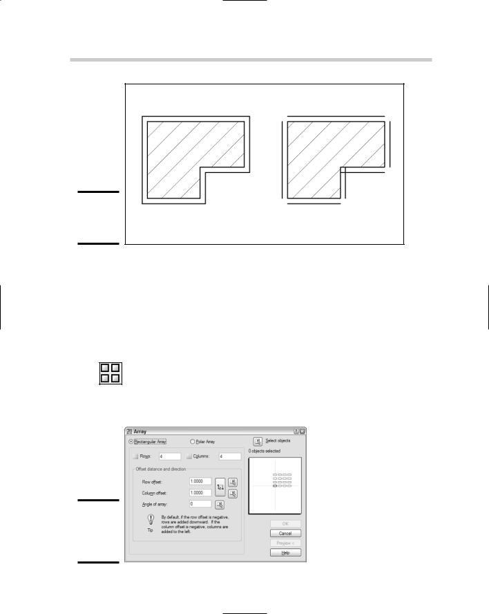
Figure 2-6 shows the effect of offsetting a set of joined linework. The closed shape on the left is a single polyline, and the shape on the right is drawn as separate lines with the LINE command. For this kind of result, it’s obviously best to use a polyline rather than separate lines — you’ll end up with no intersection cleanup.
Book II
Chapter 2
Objects Modifying
160 AutoCAD’s Editing Commands
Figure 2-6:
Offsetting polylines and lines.
Figure 2-7:
Setting a rectangular array in a dialog box.
ARRAY
COPY makes multiple copies of objects by default. If it doesn’t matter where the copies go, the COPY command is fine. However, if you need your ducks in rows (and columns, or even in a circle), the ARRAY command is for you.
ARRAY creates regular patterns of selected objects in either Rectangular (rows and columns) or Polar (circular) arrangements. The following steps explain how to create a rectangular array:
1.Choose Modify Array, click Array on the Modify toolbar, or type AR to start the ARRAY command.
The Array dialog box appears. Figure 2-7 shows the dialog configured for rectangular arrays.
AutoCAD’s Editing Commands 161
2.Make sure that the Rectangular Array radio button is selected, and then click the Select Objects button.
The dialog box closes, allowing you to select objects to array.
3.Select one or more objects to array, and then press Enter to finish selecting.
The dialog box reappears.
4.Specify the number of rows and/or columns, the row and column offsets, and (optionally) a rotation angle for the array.
If you want a single row or a single column, specify 1 in the appropriate box. Also, even though you’re making copies of a source object, the number of rows and columns must include the number of copies you want plus the source object.
You can also use the buttons beside the Row offset, Column offset, and Angle of array boxes to specify distances and angles. Clicking any of the buttons temporarily closes the dialog box and lets you pick points in the drawing.
5.Click Preview to make sure your ducks are in a row.
The main Array dialog box disappears again, and AutoCAD previews the results of your settings together with a small dialog box with buttons to Accept, Modify, or Cancel.
6.Click Accept to finish the command, or Modify to return to the dialog box, or Cancel to forget the whole business.
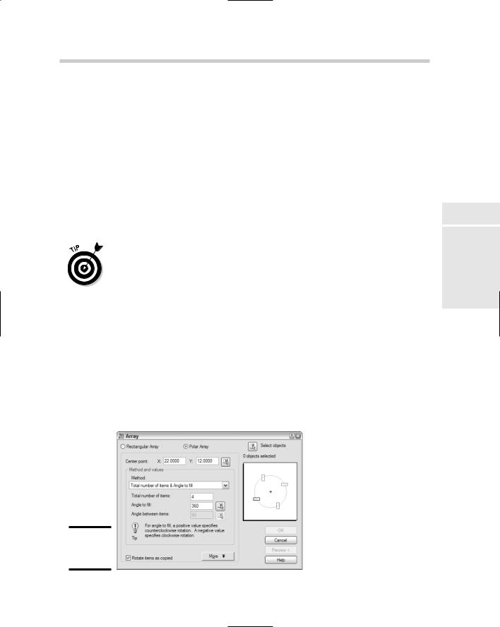
Choosing a polar array changes the look of the Array dialog box (see Figure 2-8). To create a polar array, you specify objects to array, and then a center point, the number of items and angle to fill, and whether the selected objects should be rotated as they’re arrayed.
Figure 2-8:
Setting up a polar array.
Book II
Chapter 2
Objects Modifying