

Bits Is Bits (and Bytes Is Bits)
Assembly language is big on bits.
Bits, after all, are what bytes are made of, and one essential assembly language skill is building bytes and taking them apart again. A technique called bit mapping is widely used in assembly language. Bit mapping assigns special meanings to individual bits within a byte to save space and squeeze the last little bit of utility out of a given amount of memory.
There is a family of instructions in the x86 instruction set that allows you to manipulate the bits within the bytes by applying Boolean logical operations to the bytes on a bit-by-bit basis. These are the bitwise logical instructions: AND, OR, XOR, and NOT. Another family of instructions allows you to slide bits back and forth within a single byte or word. These are the most-used shift/rotate instructions: ROL,
ROR, RCL, RCR, SHL, and SHR. (There are a few others that I will not be discussing in this book.)
Bit Numbering
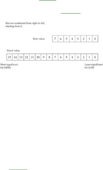
Dealing with bits requires that we have a way of specifying which bits we're dealing with. By convention, bits in assembly language are numbered, starting from 0, at the least-significant bit in the byte, word, or other item we're using as a bit map. The least-significant bit is the one with the least value in the binary number system. (Return to Chapter 2 and reread the material on base 2 if that seems fuzzy to you.) It's also the bit on the far right, if you write the value down as a binary number.
It works best as a visual metaphor. See Figure 10.1.
Figure 10.1: Bit numbering.
When you count bits, start with the bit on the right, and number them from 0.
"It's the Logical Thing to Do, Jim . . ."
Boolean logic sounds arcane and forbidding, but remarkably, it reflects the realities of ordinary thought and action. The Boolean operator AND, for instance, pops up in many of the decisions you make every day of your life. For example, to write a check that doesn't bounce, you must have money in your checking account AND checks in your checkbook. Neither alone will do the job. ("How can I be overdrawn?" goes the classic question, "I still have checks in my checkbook!") You can't write a check you don't have, and a check without money behind it will bounce. People who live out of their checkbooks (and they always end up ahead of me in the checkout line at Safeway) must use the AND operator frequently.
When mathematicians speak of Boolean logic, they manipulate abstract values called True and False. The AND operator works like this. Condition1 AND Condition2 will be considered True if both
Condition1 and Condition2 are True. If either condition is False, the result will be False.
There are in fact four different combinations of the two input values, so logical operations between two values are usually summarized in a form called a truth table. The truth table for the AND operator is shown in Table 10.1.

Table 10.1: The AND Truth Table for Formal Logic
|
|
|
|
|
|
|
|
|
|
CONDITION1 |
|
OPERATOR |
|
CONDITION2 |
|
RESULT |
|
|
|
|
|
|
|
|
|
|
|
False |
|
AND |
|
False = |
|
False |
|
|
|
|
|
|
|
|
|
|
|
False |
|
AND |
|
True = |
|
False |
|
|
|
|
|
|
|
|
|
|
|
True |
|
AND |
|
False = |
|
False |
|
|
|
|
|
|
|
|
|
|
|
True |
|
AND |
|
True = |
|
True |
|
|
|
|
|
|
|
|
|
|
There's nothing mysterious about the truth table. It's just a summary of all possibilities of the AND operator as applied to two input conditions. The important thing to remember is that only when both input values are True will the result also be True.
That's the way mathematicians see AND. In assembly language terms, the AND instruction looks at two bits and yields a third bit based on the values of the first two bits. By convention, we consider a 1 bit to be True and a 0 bit to be False. The logic is identical; we're just using different symbols to represent True and False. Keeping that in mind, we can rewrite AND's truth table to make it more meaningful for assembly language work. See Table 10.2.
Table 10.2: The AND Truth Table for Assembly Language
|
|
|
|
|
|
|
|
|
|
BIT 1 |
|
OPERATOR |
|
BIT 2 |
|
RESULT BIT |
|
|
|
|
|
|
|
|
||
|
0 |
|
AND |
|
0 = |
|
0 |
|
|
|
|
|
|
|
|
||
|
0 |
|
AND |
|
1 = |
|
0 |
|
|
|
|
|
|
|
|
||
|
1 |
|
AND |
|
0 = |
|
0 |
|
|
|
|
|
|
|
|
||
|
1 |
|
AND |
|
1 = |
|
1 |
|
|
|
|
|
|
|
|
|
|
The AND Instruction
The AND instruction embodies this concept in the x86 instruction set. The AND instruction performs the AND logical operation on two like-sized operands and replaces its first operand with the result of the operation. (By first, I mean the operand closest to the mnemonic.) In other words, consider this instruction:
AND AL,BL
What will happen here is that the CPU will perform a gang of eight bitwise AND operations on the eight bits in AL and BL. Bit 0 of AL is ANDed with bit 0 of BL, bit 1 of AL is ANDed with bit 1 of BL, and so on. Each AND operation generates a result bit, and that bit is placed in the first operand (here, AL) after all eight AND operations occur. This is a common thread among machine instructions that perform some operation on two operands and produce a result: The result replaces the first operand, not the second!
Masking Out Bits
A major use of the AND instruction is to isolate one or more bits out of a byte value or a word value.
Isolate here simply means to set all unwanted bits to a reliable 0 value. As an example, suppose we are interested in testing bits 4 and 5 of a value to see what those bits are. To do that, we have to be able to ignore the other bits (bits 0 through 3 and 6 through 7), and the only way to safely ignore bits is to set them to 0.
AND is the way to go. We set up a bit mask in which the bit numbers that we want to inspect and test are set to 1, and the bits we wish to ignore are set to 0. To mask out all bits but bits 4 and 5, we must set up a mask in which bits 4 and 5 are set to 1, with all other bits at 0. This mask in binary is 00110000B, or 30H. (To verify it, count the bits from the right-hand end of the binary number, starting with 0.) This bit mask is then ANDed against the value in question. Figure 10.2 shows this operation in action, with the 30H bit mask just described and an initial value of 9DH.
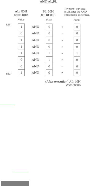
Figure 10.2: The anatomy of an AND instruction.
The three binary values involved are shown laid out vertically, with the LSB (that is, the right-hand end) of each value at the top. You should be able to trace each AND operation and verify it by looking at Table 10.2.
The end result is that all but bits 4 and 5 are guaranteed to be 0 and can thus be safely ignored. Bits 4 and 5 could be either 0 or 1. (That's why we need to test them; we don't know what they are.) With the initial value of 9DH, bit 4 turns out to be a 1, and bit 5 turns out to be a 0. If the initial value were something else, bits 4 and 5 could both be 0, both be 1, or some combination of the two.
Don't forget: The result of the AND operation replaces the first operand after the operation is complete.
For an example of the AND instruction in operation isolating bits in a word, look ahead to the Byte2Str procedure, which follows later in this chapter.
The OR Instruction
Closely related to the AND logical operation is OR, which, like the AND logical operation, has an embodiment with the same name in the x86 instruction set. Structurally, the OR instruction works identically to AND. Only its truth table is different: While AND requires that both its operands be 1 for the result to be 1, OR is satisfied that at least one operand has a 1 value. The truth table for OR is shown in Table 10.3.
Table 10.3: The OR Truth Table for Assembly Language
|
|
|
|
|
|
|
|
|
|
BIT 1 |
|
OPERATOR |
|
BIT 2 |
|
RESULT BIT |
|
|
|
|
|
|
|
|
||
|
0 |
|
OR |
|
0 = |
|
0 |
|
|
|
|
|
|
|
|
||
|
0 |
|
OR |
|
1 = |
|
1 |
|
|
|
|
|
|
|
|
||
|
1 |
|
OR |
|
0 = |
|
1 |
|
|
|
|
|
|
|
|
||
|
1 |
|
OR |
|
1 = |
|
1 |
|
|
|
|
|
|
|
|
|
|
Because it's unsuitable for isolating bits, OR is used much more rarely than AND.
The XOR Instruction
In a class by itself is the exclusive OR operation, embodied in the XOR instruction. XOR, again, does in broad terms what AND and OR do: It performs a logical operation on two operands, and the result replaces the first operand. The logical operation, however, is exclusive or, meaning that the result is 1 only if the two operands are different (that is, 1 and 0 or 0 and 1). The truth table for XOR (Table 10.4) should make this slippery notion a little clearer.
Table 10.4: The XOR Truth Table for Assembly Language
|
|
|
|
|
|
|
|
|
|
BIT 1 |
|
OPERATOR |
|
BIT 2 |
|
RESULT BIT |
|
|
|
|
|
|
|
|
||
|
0 |
|
XOR |
|
0 = |
|
0 |
|
|
|
|
|
|
|
|
||
|
0 |
|
XOR |
|
1 = |
|
1 |
|
|
|
|
|
|
|
|
||
|
1 |
|
XOR |
|
0 = |
|
1 |
|
|
|
|
|
|
|
|
||
|
1 |
|
XOR |
|
1 = |
|
0 |
|
|
|
|
|
|
|
|
|
|
Look Table 10.4 over carefully! In the first and last cases, where the two operands are the same, the result is 0. In the middle two cases, where the two operands are different, the result is 1.
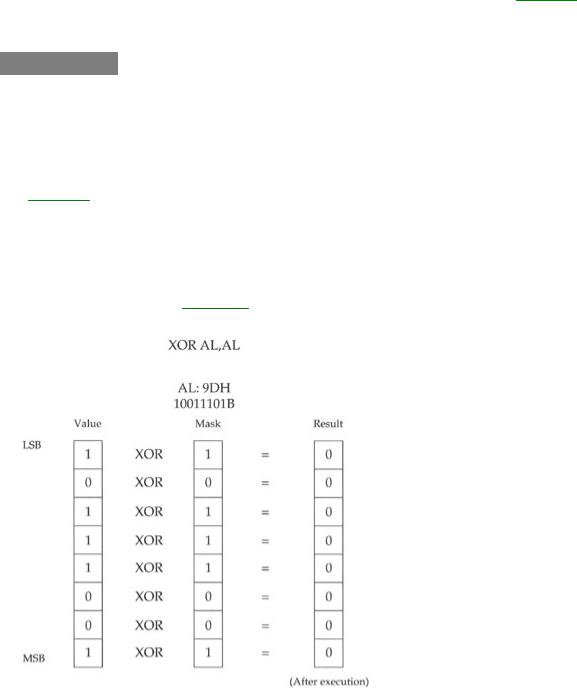
Some interesting things can be done with XOR, but most of them are a little arcane for a beginners' book. I will show you one handy XOR trick, however: XORing any value against itself yields 0. In the old days, this was faster than loading a 0 into a register from immediate data. Although that's no longer the case, it's an interesting trick to know. How it works should be obvious from reading the truth table, but to drive it home I've laid it out in Figure 10.3.
Figure 10.3: Using XOR to zero a register.
Follow each of the individual XOR operations across the figure to its result value. Because each bit in AL is XORed against itself, in every case the XOR operations happen between two operands that are identical. Sometimes both are 1, sometimes both are 0, but in every case the two are the same. With the XOR operation, when the two operands are the same, the result is always 0. Voila! Zero in a register.
The NOT Instruction
Easiest to understand of all the bitwise logical instructions is NOT. The truth table for NOT is simpler than the others we've looked at because NOT only takes one operand. And what it does is simple as well: NOT takes the state of each bit in its single operand and changes it to its opposite state. What

was 1 becomes 0 and what was 0 becomes 1. I show it in Table 10.5.
Table 10.5: The NOT Truth Table for Assembly Language
|
|
|
|
|
|
|
|
BIT |
|
OPERATOR |
|
RESULT BIT |
|
|
|
|
|
|
|
|
|
0 |
|
NOT |
|
1 |
|
|
|
|
|
|
|
|
|
1 |
|
NOT |
|
0 |
|
|
|
|
|
|
|
|
Segment Registers Don't Respond to Logic!
One limitation of the segment registers CS, DS, SS, ES, FS, and GS is that they cannot be used with any of the bitwise logical instructions. If you try, the assembler will hand you an "Illegal use of segment register" error. If you need to perform a logical operation on a segment register, you must first copy the segment register's value into one of the registers AX, BX, CX, DX, BP, SI, and DI; perform the logical operation on the new register; and then copy the result back into the segment register.
Banging bits in segment registers is a dicey business if what's in the segment register is truly a segment address. Sometimes it would be handy to use segment registers as spare, general-purpose registers, but this can only be done in real mode. In real work in today's world, you're likely to be working in protected mode, where segment registers can only be used as segment registers. So, it's really not losing any genuine chip features, but gaining 4 gigabytes of memory instead. That's a bargain I can live with.