D
|
H |
Node discard packets |
|
G |
that have been seen |
|
Reply packet follows the |
x |
|
reverse path of |
|
|
|
the route request packet |
|
|
recorded in broadcast |
|
|
packet |
F |
|
|
B
E
Neighbors re-broadcast the packet until it reaches the intended destination
Node discard packets that have been seen
C
x
EQ
RR
D
A
Source broadcasts
S a route request packet
Figure 13.13 AODV – path finding.
Source
Height
metric
Destination
link (i, j) E, is assumed to be bidirectional, i.e. it allows two-way communications. The height metric associated with each node is of the form Hi = (τ i, oidi, ri, δi, i) where:
τ i is the logical time of a link failure, and defines a new reference level;
oidi is the unique ID of the node that defined the reference level;
ri denotes two unique sub-levels of a reference level;
δi is used to order the nodes with respect to a common reference level; and
iis the unique ID of the node itself.
Each node i (other than the destination) maintains its height Hi. Initially the height is set to NULL, Hi = [–, –, –, –, i]. The height of the destination is always ZERO, HdID = [0, 0, 0, 0, dID]. At each node there is a height array with an entry NHi,j for each neighbor i, V. Initially the height of each neighbor is set to NULL; if a neighbor is a destination its corresponding entry in the height array is set to ZERO.
The operation of TORA protocols is illustrated in Figures 13.15–13.18. The protocols are well suited for networks with large dense populations of nodes. They posses the ability to detect network partitions and erase all invalid routes within a finite time.
Protocol quickly creates and maintains routes for a destination for which routing is desired. It minimizes the number of nodes reacting to topological changes. It needs a synchronization mechanism to achieve a temporal order of events.
13.1.2.8 Associativity-based routing
The associativity based routing (ABR) protocol [12] is free from loops, deadlock and packet duplicates, and defines a different routing metric for ad hoc mobile networks. This metric is known as the degree of association stability. In ABR, a route is selected based on the degree of association stability of mobile nodes. Each node periodically generates a beacon to signify its existence. When received by neighboring nodes, this beacon causes their associativity tables to be updated. For each beacon received, the associativity tick of the current node with respect to the beaconing node is incremented. Association stability is defined by connection stability of one node with respect to another node over time and space. A high degree of association stability may indicate a low state of node mobility, while a low degree may indicate a high state of node mobility. Associativity ticks are reset when the neighbors of a node or the node itself move out of proximity. A fundamental objective of ABR is to derive longer-lived routes for ad hoc mobile networks.
The three phases of ABR are: (1) route discovery; (2) route reconstruction (RRC); and (3) route deletion. The route discovery phase is accomplished by a broadcast query and await-reply (BQ-REPLY) cycle. A node desiring a route broadcasts a BQ message in search of mobiles that have a route to the destination. All nodes receiving the query (that are not the destination) append their addresses and their associativity ticks with their neighbors along with QoS information to the query packet. A successor node erases its upstream node neighbors’ associativity tick entries and retains only the entry concerned with itself and its upstream node. In this way, each resultant packet arriving at the destination will contain the associativity ticks of the nodes along the route to the destination. The destination is then able to select the best route by examining the associativity ticks along each of the paths.
[ñ–,ñ–,ñ–,ñ–,E]
Y
Q
[–ñ,–ñ,–ñ,–ñ,B] |
B |
|
B and D |
|
propagate QRY
Y
R
Q
,D] |
|
|
[–ñ,–ñ,–ñ,–ñ,H] |
|
|
|
,ñ– |
|
|
HH |
,ñ– |
|
|
|
|
Y |
,ñ– |
|
R |
[ñ– |
|
Q |
|
|
D |
|
QRY |
andA G |
QRY |
Q |
GG [–ñ,–ñ,–ñ,–ñ,G] |
propagate |
|
|
|
Y |
|
C initiates
QRY
[0,0,0,0,F] FF
[–ñ,–ñ,–ñ,–ñ,E] EE
[–ñ,–ñ,–ñ,–ñ,B] BB
H generates UPD
H [0,0,0,1,H]
GG [–ñ,–ñ,–ñ,–ñ,G]
[–ñ,–ñ,–ñ,–ñ,A] AA
CC [–ñ,–ñ,–ñ,–ñ,C]
Figure 13.15 TORA – route creation.
When multiple paths have the same overall degree of association stability, the route with the minimum number of hops is selected. The destination then sends a REPLY packet back to the source along this path. Nodes propagating the REPLY mark their routes as valid. All other routes remain inactive, and the possibility of duplicate packets arriving at the destination is avoided. RRC may consist of partial route discovery, invalid route erasure, valid route updates and new route discovery, depending on which node(s) along the route move. Movement by the source results in a new BQ-REPLY process. The RN message is a route notification used to erase the route entries associated with downstream nodes. When the destination moves, the immediate upstream node erases its route and determines if the node is still reachable by a localized query (LQ[H]) process, where H refers to the hop count from the upstream node to the destination. If the destination receives the LO
|
|
|
[0,0,0,0,F] |
F |
|
|
[0,0,0,1,E] |
D |
E |
,D]2,0, |
|
H |
[0,0,0,1,H] |
|
|
|
|
|
U |
P |
|
|
,0 |
|
|
|
|
|
|
|
|
[0 |
|
|
|
|
|
|
UPD |
|
|
|
|
[–ñ,ñ–,–ñ,–ñ,B] |
|
B |
|
D |
|
|
|
|
|
|
|
|
|
D and G probagate UPD, |
|
|
|
D |
|
|
|
|
E generates UPD |
|
|
|
|
|
G |
[0,0,0,2,G] |
|
|
U |
P |
|
|
|
|
|
|
|
|
D |
|
|
|
|
|
|
U |
P |
|
[–ñ,–ñ,–ñ,–ñ,A] |
|
|
|
|
|
|
|
|
A |
|
|
|
|
|
|
|
|
|
|
|
|
|
|
C |
[–ñ,–ñ,–ñ,–ñ,C] |
0,,2,D] |
[0,0,0,1,H] |
H |
[0,0 |
|
[0,0,0,2,B] B
A, B and C propagate UPD
D
P
U
[0,0,0,3,A]
D
D |
G [0,0,0,2,G] |
UP |
A |
|
C |
[0,0,0,3,C] |
DP |
|
U |
|
Figure 13.15 Continued.
packet, it REPLYs with the best partial route; otherwise, the initiating node times out and the process backtracks to the next upstream node. Here an RN message is sent to the next upstream node to erase the invalid route and inform this node that it should invoke the LQ process. If this process results in backtracking more than halfway to the source, the LO process is discontinued and a new BQ process is initiated at the source. When a discovered route is no longer desired, the source node initiates a route delete (RD) broadcast so that all nodes along the route update their routing tables. The RD message is propagated by a full broadcast, as opposed to a directed broadcast, because the source node may not be aware of any route node changes that occurred during RRCs.
13.1.2.9 Signal stability routing
Another on-demand protocol is the signal stability-based adaptive routing protocol (SSR) presented in Dube et al. [13]. Unlike the algorithms described so far, SSR selects routes
482 |
AD HOC NETWORKS |
|
|
|
|
|
[0,0,0,3,C] |
|
[0,0,0,3,A] |
|
|
|
|
Source |
A |
|
|
|
|
|
C |
|
|
|
|
|
|
|
[0,0,0,2,D] |
B |
[0,0,0,2,B] |
|
|
|
|
|
|
D |
|
|
|
|
|
|
G |
|
|
E |
|
|
|
|
|
|
[0,0,0,1,E] |
|
[0,0,0,2,G] |
|
|
|
|
|
|
|
|
|
|
|
|
|
H |
|
|
|
|
|
[0,0,0,1,H] |
|
|
|
[0,0,0,0,F] |
|
|
|
|
F |
|
Destination |
|
|
|
|
|
|
Figure 13.16 TORA – route creation (visualization).
[0,0,0,3,C] |
|
[0,0,0,3,A] |
|
Source |
A |
|
|
C |
|
|
|
|
[[0,0,0,2,D] |
[0,0,0,2,B] |
|
B |
|
|
D |
x |
|
|
|
Link (B,E) fails |
|
G |
E |
|
|
|
[0,0,0,1,E] |
[0,0,0,2,G] |
|
|
|
|
|
|
|
H |
|
|
[0,0,0,1,H] |
|
[0,0,0,0,F] |
F Destination
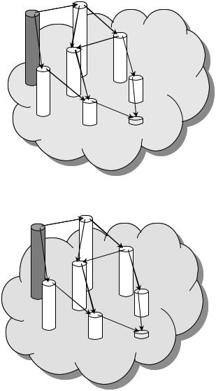
Figure 13.17 TORA – maintaining routes link failure with no reaction.
based on the signal strength between nodes and a node’s location stability. This route selection criteria has the effect of choosing routes that have ‘stronger’ connectivity. SSR can be divided into two cooperative protocols: the dynamic routing protocol (DRP) and the static routing protocol (SRP). The DRP is responsible for the maintenance of the signal stability table (SST) and routing table (RT). The SST records the signal strength of neighboring nodes, which is obtained by periodic beacons from the link layer of each neighboring node. Signal strength may be recorded as either a strong or weak channel. All transmissions are received by, and processed in, the DRP. After updating all appropriate table entries, the DRP passes a received packet to the SRP.
[0,0,0,3,C] |
[0,0,0,3,A] |
|
|
|
Source |
A |
|
|
|
C |
|
|
|
|
[0,0,0,2,D] |
B |
[0,0,0,2,B] |
|
D |
|
|
|
G |
x |
|
E |
|
|
Link (D,H) |
|
[0,0,0,1,E] |
[0,0,0,2,G] |
|
|
fails |
|
|
|
|
|
|
|
|
H |
|
|
|
[0,0,0,1,H] |
|
|
[0,0,0,0,F] |
|
|
F |
|
Destination |
|
|
|
|
|
D defines a new reference level |
|
|
|
|
|
[1,D,0,2,D] |
and broadcasts an UPD |
|
|
|
|
[0,0,0,3,C] |
D |
[0,0,0,3,A] |
|
|
|
|
|
|
|
|
|
|
|
|
|
|
|
Source |
A |
|
|
|
|
|
|
|
|
|
C |
|
|
|
|
|
|
|
|
|
|
B |
[0,0,0,2,B] |
|
|
|
|
|
|
|
|
|
|
|
|
G |
|
|
E |
|
|
|
|
|
|
|
|
|
[0,0,0,1,E] |
|
|
|
|
[0,0,0,2,G] |
|
|
|
|
|
|
|
|
|
|
|
|
|
|
|
|
|
H |
|
|
|
|
|
|
|
|
[0,0,0,1,H] |
|
|
|
[0,0,0,0,F] |
|
|
|
|
|
|
|
F |
|
Destination |
|
|
|
|
|
|
|
|
|
|
|
|
|
|
|
|
B updates its height and broadcasts an |
|
|
|
|
|
UPD to |
propagates the reference levels |
|
[0,0,0,3,C] |
|
|
D |
|
B |
[1,D,0,-1,B] |
|
Source |
|
|
|
A |
|
|
|
|
|
|
C |
|
|
|
|
|
|
|
|
|
|
|
|
[0,0,0,3,A] |
|
|
|
|
|
|
G |
|
|
|
|
|
E |
|
|
|
|
|
|
|
|
|
[0,0,0,1,E] |
|
[0,0,0,2,G] |
|
|
|
|
|
|
|
|
|
|
|
|
|
|
|
|
|
|
|
H |
|
|
|
|
|
|
[0,0,0,1,H] |
|
|
|
[0,0,0,0,F] |
|
|
|
|
|
|
|
F |
|
Destination |
|
|
|
|
|
|
|
|
|
Figure 13.18 TORA – re-establishing routes after link failure of last downstream link.
484 |
AD HOC NETWORKS |
|
|
|
[1,D,0,2,D] |
|
|
|
[0,0,0,3,C] |
D |
B [1,D,0,-1,B] |
|
|
A |
A updates its height and |
|
Source |
broadcasts an UPD to propagate |
|
C |
|
the reference level |
[1,D,0,-2,A]
G
E [0,0,0,1,E]
[0,0,0,2,G]
H
F Destination
[0,0,0,0,F] FF
[0,0,0,1,E] EE
HH [0,0,0,1,H]
[1,D,0,0,D]
GG [0,0,0,2,G]
[1,D,0,-2,A] AA
Failure reaction completed
CC [0,0,0,3,C]
Figure 13.18 Continued.
The SRP processes packets by passing the packet up the stack if it is the intended receiver or looking up the destination in the RT and then forwarding the packet if it is not. If no entry is found in the RT for the destination, a route-search process is initiated to find a route. Route requests are propagated throughout the network, but are only forwarded to the next hop if they are received over strong channels and have not been previously processed (to prevent looping). The destination chooses the first arriving route-search packet to send back because it is most probable that the packet arrived over the shortest and/or least congested path. The DRP then reverses the selected route and sends a route-reply message back to the initiator. The DRP of the nodes along the path update their RTs accordingly.
Route-search packets arriving at the destination have necessarily chosen the path of strongest signal stability, since the packets are dropped at a node if they have arrived

HYBRID ROUTING PROTOCOL |
485 |
over a weak channel. If there is no route-reply message received at the source within a specific timeout period, the source changes the PREF field in the header to indicate that weak channels are acceptable, since these may be the only links over which the packet can be propagated. When a failed link is detected within the network, the intermediate nodes send an error message to the source indicating which channel has failed. The source then initiates another route-search process to find a new path to the destination. The source also sends an erase message to notify all nodes of the broken link.
13.2 HYBRID ROUTING PROTOCOL
The zone routing protocol (ZRP) is a hybrid routing protocol that proactively maintains routes within a local region of the network (referred to as the routing zone). Knowledge of this routing zone topology is leveraged by the ZRP to improve the efficiency of a reactive route query/reply mechanism. The ZRP can be configured for a particular network through adjustment of a single parameter, the routing zone radius. A routing zone of radius r is defined for each node and includes the nodes whose minimum distance in hops from a given node is at most r hops. An example of a routing zone (for node S) of radius two hops is shown in Figure 13.19. Nodes within the circle, are said to be within the routing zone of the central node S. Nodes outside the circle are said to be outside S’s routing zone. Peripheral nodes are nodes whose minimum distance to S is exactly equal to the zone radius. The remaining nodes are categorized as interior nodes.
|
Pheripheral |
Routing zone |
node |
of radius = 2 hops |
|
S
Neighboring
node
Figure 13.19 A routing zone of radius r = 2 hops.

486 AD HOC NETWORKS
For a routing zone of radius r, the number of routing zone nodes can be regulated through adjustments in each node’s transmitter power. Subject to the local propagation conditions and receiver sensitivity, the transmission power determines the set of neighbor nodes, i.e. those nodes that are in direct communication with a node. To provide adequate network reachability, it is important that a node be connected to a sufficient number of neighbors. However, more is not necessarily better. As the transmitters’ coverage areas grow larger, so does the membership of the routing zones. This can result in an excessive amount of route update traffic.
Each node is assumed to continuously (proactively) maintain routing information only to those nodes that are within its routing zone. Because the updates are only propagated locally, the amount of update traffic required to maintain a routing zone does not depend on the total number of network nodes (which can be quite large). This is referred to as the intrazone routing protocol (IARP). The interzone routing protocol (IERP) is responsible for reactively discovering routes to destinations located beyond a node’s routing zone. The IERP operates as follows: the source node first checks whether the destination is within its zone. If so, the path to the destination is known, and no further route discovery processing is required. If the destination is not within the source’s routing zone, the source broadcasts a route request (referred to as request) to all its peripheral nodes. Now, in turn, all the peripheral nodes execute the same algorithm: they check whether the destination is within their zone. If so, a route reply (referred to as reply) is sent back to the source indicating the route to the destination. If not, the peripheral node forwards the query to its peripheral nodes, which in turn execute the same procedure.
An example of this route discovery procedure is demonstrated in Figure 13.20. The source node S needs to send a packet to the destination D. To find a route within the network, S first checks whether D is within its routing zone. If so, S knows the route to D. Otherwise, S broadcasts a query to its peripheral nodes; that is, S sends a query to nodes
G
F
E
C
S
G
H
B
B
Figure 13.20 Illustration of IERP operation.

HYBRID ROUTING PROTOCOL |
487 |
H, G and C. Now, in turn, after verifying that D is not in its routing zone, each one of these nodes forwards the query by broadcasting the query to its peripheral nodes. In particular, H sends the query to B, which recognizes D as being in its routing zone and responds to the query, indicating the forwarding path: S–H–B–D. As indicated by this example, a route can be specified by a sequence of nodes that have received the successful IERP query thread. The manner in which this information is collected and distributed is specified by a route accumulation procedure. In the basic route accumulation, a node appends its ID to a received query packet. When a node finds the destination in its zone, the accumulated sequence of IDs specifies a route between querying source and destination. By reversing the accumulated route, a path is provided back to the query source. This information can be used to return the route reply through source routing.
The intuition behind the ZRP is that querying can be performed more efficiently by broadcasting queries to the periphery of a routing zone rather than flooding the queries over the same area. However, problems can arise once the query leaves the initial routing zone. Because the routing zones heavily overlap, a node can be a member of many routing zones. It is very possible that the query will be forwarded to all the network nodes, effectively flooding the network.
Yet a more disappointing result is that the IERP can result in much more traffic than the flooding itself, due to the fact that broadcasting involves sending the query along a path equal to the zone radius. Excess route query traffic can be regarded as a result of overlapping query threads (i.e. overlapping queried routing zones). Thus, the design objective of query control mechanisms should be to reduce the amount of route query traffic by steering threads outward from the source’s routing zone and away from each other, as indicated in Figure 13.21. This problem is addressed primarily through appropriate mechanisms of query detection and query termination.
13.2.1 Loop-back termination
The query is terminated when the accumulated route (excluding the previous node) contains the host which lies in routing zone, e.g. for route = {S →A→B→C} in Figure 13.22, C terminates the query, because S is in C’s routing zone.
Desired |
|
search |
|
direction |
Desired |
|
|
search |
|
direction |
|
source |
Desired |
Desired |
search |
searchch |
direction |
direction |
|
|
Desired |
|
search |
|
direction |
Figure 13.21 Guiding the search in desirable directions.