

- •Preface
- •About This Book
- •Acknowledgments
- •Contents at a Glance
- •Contents
- •Relaxing at the Beach
- •Dressing the Scene
- •Animating Motion
- •Rendering the Final Animation
- •Summary
- •The Interface Elements
- •Using the Menus
- •Using the Toolbars
- •Using the Viewports
- •Using the Command Panel
- •Using the Lower Interface Bar Controls
- •Interacting with the Interface
- •Getting Help
- •Summary
- •Understanding 3D Space
- •Using the Viewport Navigation Controls
- •Configuring the Viewports
- •Working with Viewport Backgrounds
- •Summary
- •Working with Max Scene Files
- •Setting File Preferences
- •Importing and Exporting
- •Referencing External Objects
- •Using the File Utilities
- •Accessing File Information
- •Summary
- •Customizing Modify and Utility Panel Buttons
- •Working with Custom Interfaces
- •Configuring Paths
- •Selecting System Units
- •Setting Preferences
- •Summary
- •Creating Primitive Objects
- •Exploring the Primitive Object Types
- •Summary
- •Selecting Objects
- •Setting Object Properties
- •Hiding and Freezing Objects
- •Using Layers
- •Summary
- •Cloning Objects
- •Understanding Cloning Options
- •Mirroring Objects
- •Cloning over Time
- •Spacing Cloned Objects
- •Creating Arrays of Objects
- •Summary
- •Working with Groups
- •Building Assemblies
- •Building Links between Objects
- •Displaying Links and Hierarchies
- •Working with Linked Objects
- •Summary
- •Using the Schematic View Window
- •Working with Hierarchies
- •Setting Schematic View Preferences
- •Using List Views
- •Summary
- •Working with the Transformation Tools
- •Using Pivot Points
- •Using the Align Commands
- •Using Grids
- •Using Snap Options
- •Summary
- •Exploring the Modifier Stack
- •Exploring Modifier Types
- •Summary
- •Exploring the Modeling Types
- •Working with Subobjects
- •Modeling Helpers
- •Summary
- •Drawing in 2D
- •Editing Splines
- •Using Spline Modifiers
- •Summary
- •Creating Editable Mesh and Poly Objects
- •Editing Mesh Objects
- •Editing Poly Objects
- •Using Mesh Editing Modifiers
- •Summary
- •Introducing Patch Grids
- •Editing Patches
- •Using Modifiers on Patch Objects
- •Summary
- •Creating NURBS Curves and Surfaces
- •Editing NURBS
- •Working with NURBS
- •Summary
- •Morphing Objects
- •Creating Conform Objects
- •Creating a ShapeMerge Object
- •Creating a Terrain Object
- •Using the Mesher Object
- •Working with BlobMesh Objects
- •Creating a Scatter Object
- •Creating Connect Objects
- •Modeling with Boolean Objects
- •Creating a Loft Object
- •Summary
- •Understanding the Various Particle Systems
- •Creating a Particle System
- •Using the Spray and Snow Particle Systems
- •Using the Super Spray Particle System
- •Using the Blizzard Particle System
- •Using the PArray Particle System
- •Using the PCloud Particle System
- •Using Particle System Maps
- •Controlling Particles with Particle Flow
- •Summary
- •Understanding Material Properties
- •Working with the Material Editor
- •Using the Material/Map Browser
- •Using the Material/Map Navigator
- •Summary
- •Using the Standard Material
- •Using Shading Types
- •Accessing Other Parameters
- •Using External Tools
- •Summary
- •Using Compound Materials
- •Using Raytrace Materials
- •Using the Matte/Shadow Material
- •Using the DirectX 9 Shader
- •Applying Multiple Materials
- •Material Modifiers
- •Summary
- •Understanding Maps
- •Understanding Material Map Types
- •Using the Maps Rollout
- •Using the Map Path Utility
- •Using Map Instances
- •Summary
- •Mapping Modifiers
- •Using the Unwrap UVW modifier
- •Summary
- •Working with Cameras
- •Setting Camera Parameters
- •Summary
- •Using the Camera Tracker Utility
- •Summary
- •Using Multi-Pass Cameras
- •Creating Multi-Pass Camera Effects
- •Summary
- •Understanding the Basics of Lighting
- •Getting to Know the Light Types
- •Creating and Positioning Light Objects
- •Viewing a Scene from a Light
- •Altering Light Parameters
- •Working with Photometric Lights
- •Using the Sunlight and Daylight Systems
- •Using Volume Lights
- •Summary
- •Selecting Advanced Lighting
- •Using Local Advanced Lighting Settings
- •Tutorial: Excluding objects from light tracing
- •Summary
- •Understanding Radiosity
- •Using Local and Global Advanced Lighting Settings
- •Working with Advanced Lighting Materials
- •Using Lighting Analysis
- •Summary
- •Using the Time Controls
- •Working with Keys
- •Using the Track Bar
- •Viewing and Editing Key Values
- •Using the Motion Panel
- •Using Ghosting
- •Animating Objects
- •Working with Previews
- •Wiring Parameters
- •Animation Modifiers
- •Summary
- •Understanding Controller Types
- •Assigning Controllers
- •Setting Default Controllers
- •Examining the Various Controllers
- •Summary
- •Working with Expressions in Spinners
- •Understanding the Expression Controller Interface
- •Understanding Expression Elements
- •Using Expression Controllers
- •Summary
- •Learning the Track View Interface
- •Working with Keys
- •Editing Time
- •Editing Curves
- •Filtering Tracks
- •Working with Controllers
- •Synchronizing to a Sound Track
- •Summary
- •Understanding Your Character
- •Building Bodies
- •Summary
- •Building a Bones System
- •Using the Bone Tools
- •Using the Skin Modifier
- •Summary
- •Creating Characters
- •Working with Characters
- •Using Character Animation Techniques
- •Summary
- •Forward versus Inverse Kinematics
- •Creating an Inverse Kinematics System
- •Using the Various Inverse Kinematics Methods
- •Summary
- •Creating and Binding Space Warps
- •Understanding Space Warp Types
- •Combining Particle Systems with Space Warps
- •Summary
- •Understanding Dynamics
- •Using Dynamic Objects
- •Defining Dynamic Material Properties
- •Using Dynamic Space Warps
- •Using the Dynamics Utility
- •Using the Flex Modifier
- •Summary
- •Using reactor
- •Using reactor Collections
- •Creating reactor Objects
- •Calculating and Previewing a Simulation
- •Constraining Objects
- •reactor Troubleshooting
- •Summary
- •Understanding the Max Renderers
- •Previewing with ActiveShade
- •Render Parameters
- •Rendering Preferences
- •Creating VUE Files
- •Using the Rendered Frame Window
- •Using the RAM Player
- •Reviewing the Render Types
- •Using Command-Line Rendering
- •Creating Panoramic Images
- •Getting Printer Help
- •Creating an Environment
- •Summary
- •Creating Atmospheric Effects
- •Using the Fire Effect
- •Using the Fog Effect
- •Summary
- •Using Render Elements
- •Adding Render Effects
- •Creating Lens Effects
- •Using Other Render Effects
- •Summary
- •Using Raytrace Materials
- •Using a Raytrace Map
- •Enabling mental ray
- •Summary
- •Understanding Network Rendering
- •Network Requirements
- •Setting up a Network Rendering System
- •Starting the Network Rendering System
- •Configuring the Network Manager and Servers
- •Logging Errors
- •Using the Monitor
- •Setting up Batch Rendering
- •Summary
- •Compositing with Photoshop
- •Video Editing with Premiere
- •Video Compositing with After Effects
- •Introducing Combustion
- •Using Other Compositing Solutions
- •Summary
- •Completing Post-Production with the Video Post Interface
- •Working with Sequences
- •Adding and Editing Events
- •Working with Ranges
- •Working with Lens Effects Filters
- •Summary
- •What Is MAXScript?
- •MAXScript Tools
- •Setting MAXScript Preferences
- •Types of Scripts
- •Writing Your Own MAXScripts
- •Learning the Visual MAXScript Editor Interface
- •Laying Out a Rollout
- •Summary
- •Working with Plug-Ins
- •Locating Plug-Ins
- •Summary
- •Low-Res Modeling
- •Using Channels
- •Using Vertex Colors
- •Rendering to a Texture
- •Summary
- •Max and Architecture
- •Using AEC Objects
- •Using Architectural materials
- •Summary
- •Tutorial: Creating Icy Geometry with BlobMesh
- •Tutorial: Using Caustic Photons to Create a Disco Ball
- •Summary
- •mental ray Rendering System
- •Particle Flow
- •reactor 2.0
- •Schematic View
- •BlobMesh
- •Spline and Patch Features
- •Import and Export
- •Shell Modifier
- •Vertex Paint and Channel Info
- •Architectural Primitives and Materials
- •Minor Improvements
- •Choosing an Operating System
- •Hardware Requirements
- •Installing 3ds max 6
- •Authorizing the Software
- •Setting the Display Driver
- •Updating Max
- •Moving Max to Another Computer
- •Using Keyboard Shortcuts
- •Using the Hotkey Map
- •Main Interface Shortcuts
- •Dialog Box Shortcuts
- •Miscellaneous Shortcuts
- •System Requirements
- •Using the CDs with Windows
- •What’s on the CDs
- •Troubleshooting
- •Index
Chapter 30 Animation Basics 739
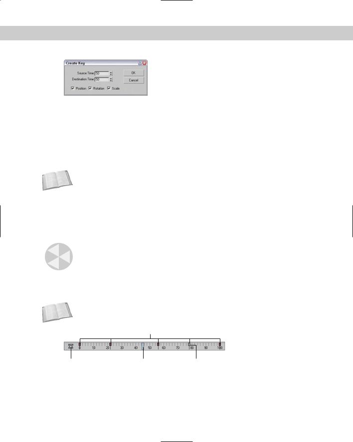
Figure 30-4: The Create Key dialog boxes enable you to create a Position, Rotation, or Scale key quickly.
If you right-click the spinner, a pop-up menu of options appears. Using this pop-up menu, you can Cut, Copy, Paste, and Delete the parameter value. You can also select Copy Animation, which copies all the keys associated with this parameter and lets you paste them to another parameter. Pasting the animation keys can be done as a Copy, an Instance, or a Wire. A Copy is independent; an Instance ties the animation keys to the original copy, so that they both are changed when either changes; and a Wire lets one parameter control some other parameter.
The right-click pop-up menu also includes commands to let you Edit a wired parameter, show the parameter in the Track View, or show the parameter in the Parameter Wire dialog box.
Cross- |
Parameter wiring and the Parameter Wire dialog box are discussed in more detail in the |
Reference |
“Using the Parameter Wiring dialog box” section later in this chapter. |
|
Using the Track Bar
The Max interface includes a simple way to work with keys: with the Track Bar, which is situated directly under the Time Slider. The Track Bar displays a rectangular marker for every key for the selected object. These markers are color-coded depending on the type of key. Position keys are red, rotation keys are green, scale keys are blue, and parameter keys are dark gray.
Caution |
In the Track View — Dope Sheet interface, position, rotation, and scale keys are red, green, |
|
and blue, but parameter keys are yellow. |
The current frame is also shown in the Track Bar as a light blue transparent rectangle, as shown in Figure 30-5. The icon at the left end of the Track Bar is the Show Curves button, which opens a mini Track View.
Cross- |
For more on the Track View interface, see Chapter 33, “Working with the Track View.” |
Reference |
|
Keys
Open Track View |
Current frame |
Selected key |
Figure 30-5: The Track Bar displays all keys for the selected object.
740 Part VII Animation
|
Using the Track Bar, you can move, copy, and delete keys. The Track Bar shows key markers |
|
only for the currently selected object or objects, and each marker can represent several differ- |
|
ent keys. When the mouse is moved over the top of these markers, the cursor changes to a |
|
plus sign, and you can select it by clicking (selected markers turn white). Using the Ctrl key, |
|
you can select multiple keys at the same time. You can also select multiple key markers by |
|
clicking an area of the Track Bar that contains no keys and then dragging an outline over all |
|
the keys you want to select. If you move the cursor over the top of a selected key, the cursor is |
|
displayed as a set of arrows enabling you to drag the selected key to the left or right. Holding |
|
down the Shift key while dragging a key creates a copy of the key. Pressing the Delete key |
|
deletes the selected key. |
Tip |
If you drag a key off the end of the Track Bar, the frame number is displayed on the Prompt |
|
Line at the bottom of the interface and the key is not included in the current time range. If |
|
you ever want to remove a key without deleting it, you can drag it off the end of the Track Bar |
|
and recover it by resetting the time in the Time Configuration dialog box. |
|
Because each marker can represent several keys, you can view all the keys associated with |
|
the marker in a pop-up menu by right-clicking on the marker. |
Note |
In the pop-up menu, a check mark next to a key indicates that the key is shared with another |
|
instance. |
|
The marker pop-up menu also offers options for deleting selected keys or filtering the keys. |
|
In addition, there is a Goto Time command, which automatically moves the Time Slider to the |
|
key’s location when selected. |
|
To delete a key marker with all of its keys, right-click to open the pop-up menu and choose |
|
Delete Key All, or select the key marker and press the Delete key. |
Viewing and Editing Key Values
At the top of the marker’s right-click pop-up menu is a list of current keys for the selected object (or if there are too many keys for a marker, they are placed under the Key Properties menu). When you select one of these keys, a key information dialog box opens. This dialog box displays different controls depending on the type of key that is selected. Figure 30-6 shows the dialog box for the Position key. There are slight variations in this dialog box depending on the key type.
Figure 30-6: Key dialog boxes enable you to change the key parameters.
Note You can also access key-specific dialog boxes in the Motion panel for a selected object by clicking the Parameters button.
Chapter 30 Animation Basics 741
Within each of these key dialog boxes is a Time value that shows the current frame. Next to the Time value are two arrows that enable you to move easily to the other keys in the scene. The dialog box also includes several text fields, where you can change the key parameters.
Most of the key dialog boxes also include flyout buttons for selecting Key Tangents. Key Tangents determine how the animation moves into and out of the key. For example, if the In Key Tangent is set to Slow and the Out Key Tangent is set to Fast, the object approaches the key position in a slow manner but accelerates as it leaves the key position. The arrow buttons on either side of the Key Tangent buttons can copy the current Key Tangent selection to the previous or next key.
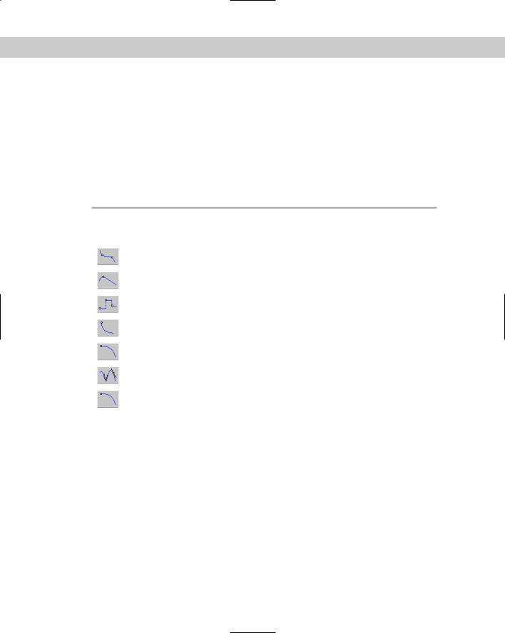
The six different types of Tangents are detailed in Table 30-3.
|
Table 30-3: Key Tangents |
|
|
|
|
Toolbar Button |
Name |
Description |
|
|
|
|
Smooth |
Produces straight, smooth motion; this is the |
|
|
default type. |
|
Linear |
Moves at a constant rate between keys |
|
Step |
Causes discontinuous motion between keys; it |
|
|
occurs only between matching In-Out pairs. |
|
Slow |
Decelerates as you approach the key |
|
Fast |
Accelerates as you approach the key |
|
Custom |
Lets you control the Tangent handles in function |
|
|
curves mode |
|
Custom – Locked Handles |
Lets you control the Tangent handles in function |
|
|
curves mode with the handles locked |
|
|
|
Using the Motion Panel
You have yet another way to create keys: by using the Motion panel. The Motion panel in the Command Panel includes settings and controls for animating objects. At the top of the Motion panel are two buttons: Parameters and Trajectories.
Setting parameters
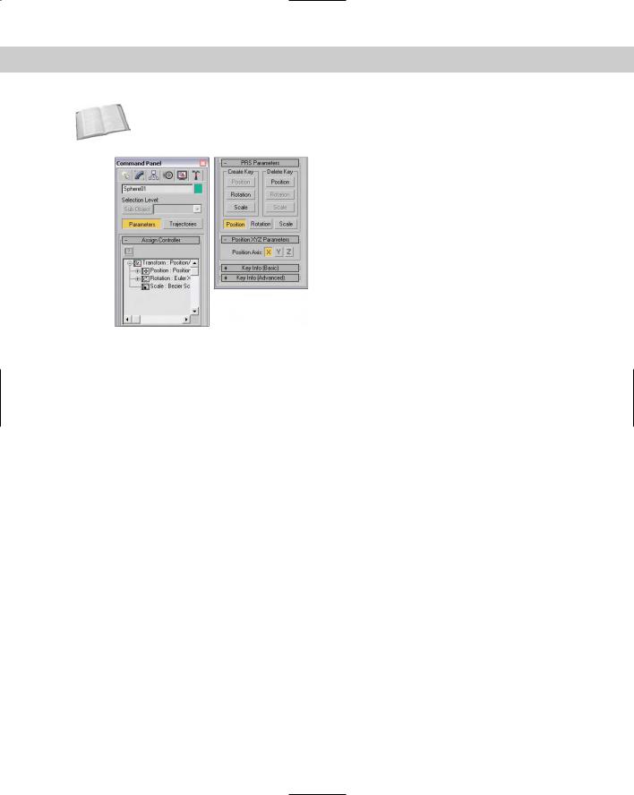
The Parameters button on the Motion panel lets you assign controllers and create and delete keys. Controllers are custom key-creating algorithms that can be defined through the Parameters rollout, shown in Figure 30-7. These controllers are assigned by selecting the position, rotation, or scaling track and clicking the Assign Controller button to open a list of applicable controllers that you can select.
742 Part VII Animation
Cross-
Reference
For more information on controllers, see Chapter 31, “Animating with Constraints and Controllers.”
Figure 30-7: The Parameters section of the Motion panel lets you assign controllers and create keys.
Below the Assign Controllers rollout is the PRS Parameters rollout, where you can create and delete Position, Rotation, and Scale keys. You can use this rollout to create keys whether or not the Auto Key or Set Key buttons are enabled. Additional rollouts may be available, depending upon the selected controller.
Below the PRS Parameters rollout are two Key Info rollouts: Basic and Advanced. These rollouts include the same key-specific information that you can access using the right-click pop-up menu found in the Track Bar.
Using trajectories
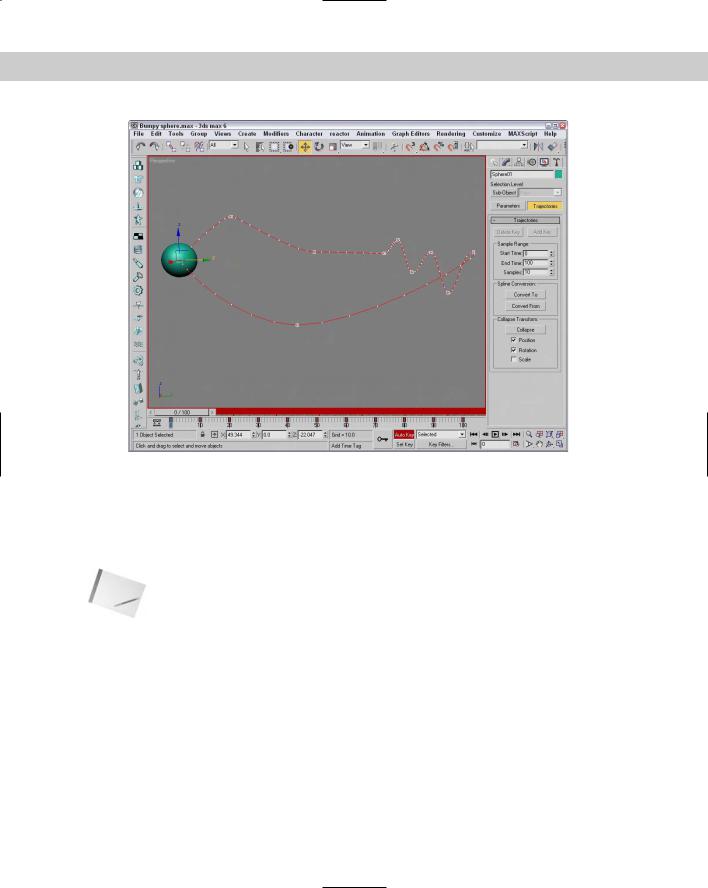
A trajectory is the actual path that the animation follows. When you click the Trajectories button in the Motion panel, the animation trajectory is shown as a spline with each key displayed as a node and each frame shown as a white dot. You can then edit the trajectory and its nodes by clicking the Sub-Object button at the top of the Motion panel, shown in Figure 30-8. The only subobject available is Keys. With the Sub-Object button enabled, you can use the transform buttons to move and reposition the trajectory nodes. You can also add and delete keys with the Add Key and Delete Key buttons.
For more control over the trajectory path, you can convert the trajectory path to a normal editable spline with the Convert To button. You can also convert an existing spline into a trajectory with the Convert From button.
To use the Convert From button, select an object, click the Convert From button, and then click a spline path in the scene. This creates a new trajectory path for the selected object. The first key of this path is the selected object’s original position, and the second key is located at the spline’s first vertex position. Additional keys are added as determined by the Samples value listed in the Sample Range group. All these new keys are equally spaced between the Start and End times. The selected spline is traversed from its initial vertex around the spline in order to the last vertex.
Chapter 30 Animation Basics 743
Figure 30-8: The Trajectories rollout in the Motion panel enables you to see the animation path as a spline.
Click the Collapse button at the bottom of the Trajectories rollout to reduce all transform keys into a single editable path. You can select which transformations to collapse including Position, Rotation, and Scale using the options under the Collapse button. For example, an object with several Controllers assigned can be collapsed, thereby reducing the complexity of all the keys.
Note |
If you collapse all keys, you cannot alter their parameters via the controller rollouts. |
The Views menu includes an option to Show Key Times. Enabling this option causes the display of the frame numbers next to any key along a trajectory path. You can make the trajectory visible for any object by enabling the Trajectory option in the Object Properties dialog box.
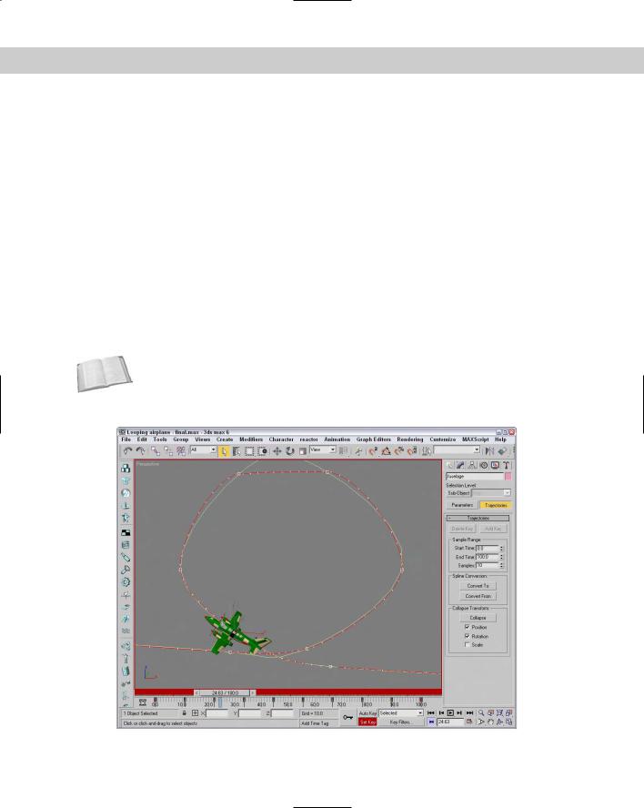
Tutorial: Making an airplane follow a looping path
Airplanes that perform aerobatic stunts often follow paths that are smooth. You can see this clearly when watching a sky writer. In this example, I’ve created a simple looping path using the Line spline primitive, and we use this path to make a plane complete a loop.
744 Part VII Animation
To make an airplane follow a looping path, follow these steps:
Cross-
Reference
1.Open the Looping airplane.max file from the Chap 30 directory on the CD-ROM.
This file includes a simple looping spline path and an airplane created by Viewpoint Datalabs.
2.With the airplane selected, open the Motion panel and click on the Trajectories button. Then click the Convert From button in the Trajectories rollout, and select the path in the Front viewport.
3.If you drag the Time Slider, you’ll notice that the plane moves along the path, but it doesn’t rotate with the path. To fix this, click the Key Mode Toggle button in the Time Controls to easily move from key to key. Click the Key Filters button, select only Rotation, and then click the Set Key button (or press the ' key) to enter Set Key mode.
4.Select the Select and Rotate button, rotate the plane in the Front viewport to match the path, and click the large Set Keys button (or press the K key) to create a rotation key. Click the Next Key button to move to the next key, and repeat this step until rotation keys have been set for the entire path.
5.Drag the Time Slider and watch the airplane circle about the loop.
There is an easier way to make the plane follow the path using the Path constraint. To learn more about constraints, see Chapter 31, “Animating with Constraints and Controllers.”
Figure 30-9 shows the plane’s trajectory.
Figure 30-9: Using a spline path, the position keys are automatically set for this plane.