

- •Preface
- •About This Book
- •Acknowledgments
- •Contents at a Glance
- •Contents
- •Relaxing at the Beach
- •Dressing the Scene
- •Animating Motion
- •Rendering the Final Animation
- •Summary
- •The Interface Elements
- •Using the Menus
- •Using the Toolbars
- •Using the Viewports
- •Using the Command Panel
- •Using the Lower Interface Bar Controls
- •Interacting with the Interface
- •Getting Help
- •Summary
- •Understanding 3D Space
- •Using the Viewport Navigation Controls
- •Configuring the Viewports
- •Working with Viewport Backgrounds
- •Summary
- •Working with Max Scene Files
- •Setting File Preferences
- •Importing and Exporting
- •Referencing External Objects
- •Using the File Utilities
- •Accessing File Information
- •Summary
- •Customizing Modify and Utility Panel Buttons
- •Working with Custom Interfaces
- •Configuring Paths
- •Selecting System Units
- •Setting Preferences
- •Summary
- •Creating Primitive Objects
- •Exploring the Primitive Object Types
- •Summary
- •Selecting Objects
- •Setting Object Properties
- •Hiding and Freezing Objects
- •Using Layers
- •Summary
- •Cloning Objects
- •Understanding Cloning Options
- •Mirroring Objects
- •Cloning over Time
- •Spacing Cloned Objects
- •Creating Arrays of Objects
- •Summary
- •Working with Groups
- •Building Assemblies
- •Building Links between Objects
- •Displaying Links and Hierarchies
- •Working with Linked Objects
- •Summary
- •Using the Schematic View Window
- •Working with Hierarchies
- •Setting Schematic View Preferences
- •Using List Views
- •Summary
- •Working with the Transformation Tools
- •Using Pivot Points
- •Using the Align Commands
- •Using Grids
- •Using Snap Options
- •Summary
- •Exploring the Modifier Stack
- •Exploring Modifier Types
- •Summary
- •Exploring the Modeling Types
- •Working with Subobjects
- •Modeling Helpers
- •Summary
- •Drawing in 2D
- •Editing Splines
- •Using Spline Modifiers
- •Summary
- •Creating Editable Mesh and Poly Objects
- •Editing Mesh Objects
- •Editing Poly Objects
- •Using Mesh Editing Modifiers
- •Summary
- •Introducing Patch Grids
- •Editing Patches
- •Using Modifiers on Patch Objects
- •Summary
- •Creating NURBS Curves and Surfaces
- •Editing NURBS
- •Working with NURBS
- •Summary
- •Morphing Objects
- •Creating Conform Objects
- •Creating a ShapeMerge Object
- •Creating a Terrain Object
- •Using the Mesher Object
- •Working with BlobMesh Objects
- •Creating a Scatter Object
- •Creating Connect Objects
- •Modeling with Boolean Objects
- •Creating a Loft Object
- •Summary
- •Understanding the Various Particle Systems
- •Creating a Particle System
- •Using the Spray and Snow Particle Systems
- •Using the Super Spray Particle System
- •Using the Blizzard Particle System
- •Using the PArray Particle System
- •Using the PCloud Particle System
- •Using Particle System Maps
- •Controlling Particles with Particle Flow
- •Summary
- •Understanding Material Properties
- •Working with the Material Editor
- •Using the Material/Map Browser
- •Using the Material/Map Navigator
- •Summary
- •Using the Standard Material
- •Using Shading Types
- •Accessing Other Parameters
- •Using External Tools
- •Summary
- •Using Compound Materials
- •Using Raytrace Materials
- •Using the Matte/Shadow Material
- •Using the DirectX 9 Shader
- •Applying Multiple Materials
- •Material Modifiers
- •Summary
- •Understanding Maps
- •Understanding Material Map Types
- •Using the Maps Rollout
- •Using the Map Path Utility
- •Using Map Instances
- •Summary
- •Mapping Modifiers
- •Using the Unwrap UVW modifier
- •Summary
- •Working with Cameras
- •Setting Camera Parameters
- •Summary
- •Using the Camera Tracker Utility
- •Summary
- •Using Multi-Pass Cameras
- •Creating Multi-Pass Camera Effects
- •Summary
- •Understanding the Basics of Lighting
- •Getting to Know the Light Types
- •Creating and Positioning Light Objects
- •Viewing a Scene from a Light
- •Altering Light Parameters
- •Working with Photometric Lights
- •Using the Sunlight and Daylight Systems
- •Using Volume Lights
- •Summary
- •Selecting Advanced Lighting
- •Using Local Advanced Lighting Settings
- •Tutorial: Excluding objects from light tracing
- •Summary
- •Understanding Radiosity
- •Using Local and Global Advanced Lighting Settings
- •Working with Advanced Lighting Materials
- •Using Lighting Analysis
- •Summary
- •Using the Time Controls
- •Working with Keys
- •Using the Track Bar
- •Viewing and Editing Key Values
- •Using the Motion Panel
- •Using Ghosting
- •Animating Objects
- •Working with Previews
- •Wiring Parameters
- •Animation Modifiers
- •Summary
- •Understanding Controller Types
- •Assigning Controllers
- •Setting Default Controllers
- •Examining the Various Controllers
- •Summary
- •Working with Expressions in Spinners
- •Understanding the Expression Controller Interface
- •Understanding Expression Elements
- •Using Expression Controllers
- •Summary
- •Learning the Track View Interface
- •Working with Keys
- •Editing Time
- •Editing Curves
- •Filtering Tracks
- •Working with Controllers
- •Synchronizing to a Sound Track
- •Summary
- •Understanding Your Character
- •Building Bodies
- •Summary
- •Building a Bones System
- •Using the Bone Tools
- •Using the Skin Modifier
- •Summary
- •Creating Characters
- •Working with Characters
- •Using Character Animation Techniques
- •Summary
- •Forward versus Inverse Kinematics
- •Creating an Inverse Kinematics System
- •Using the Various Inverse Kinematics Methods
- •Summary
- •Creating and Binding Space Warps
- •Understanding Space Warp Types
- •Combining Particle Systems with Space Warps
- •Summary
- •Understanding Dynamics
- •Using Dynamic Objects
- •Defining Dynamic Material Properties
- •Using Dynamic Space Warps
- •Using the Dynamics Utility
- •Using the Flex Modifier
- •Summary
- •Using reactor
- •Using reactor Collections
- •Creating reactor Objects
- •Calculating and Previewing a Simulation
- •Constraining Objects
- •reactor Troubleshooting
- •Summary
- •Understanding the Max Renderers
- •Previewing with ActiveShade
- •Render Parameters
- •Rendering Preferences
- •Creating VUE Files
- •Using the Rendered Frame Window
- •Using the RAM Player
- •Reviewing the Render Types
- •Using Command-Line Rendering
- •Creating Panoramic Images
- •Getting Printer Help
- •Creating an Environment
- •Summary
- •Creating Atmospheric Effects
- •Using the Fire Effect
- •Using the Fog Effect
- •Summary
- •Using Render Elements
- •Adding Render Effects
- •Creating Lens Effects
- •Using Other Render Effects
- •Summary
- •Using Raytrace Materials
- •Using a Raytrace Map
- •Enabling mental ray
- •Summary
- •Understanding Network Rendering
- •Network Requirements
- •Setting up a Network Rendering System
- •Starting the Network Rendering System
- •Configuring the Network Manager and Servers
- •Logging Errors
- •Using the Monitor
- •Setting up Batch Rendering
- •Summary
- •Compositing with Photoshop
- •Video Editing with Premiere
- •Video Compositing with After Effects
- •Introducing Combustion
- •Using Other Compositing Solutions
- •Summary
- •Completing Post-Production with the Video Post Interface
- •Working with Sequences
- •Adding and Editing Events
- •Working with Ranges
- •Working with Lens Effects Filters
- •Summary
- •What Is MAXScript?
- •MAXScript Tools
- •Setting MAXScript Preferences
- •Types of Scripts
- •Writing Your Own MAXScripts
- •Learning the Visual MAXScript Editor Interface
- •Laying Out a Rollout
- •Summary
- •Working with Plug-Ins
- •Locating Plug-Ins
- •Summary
- •Low-Res Modeling
- •Using Channels
- •Using Vertex Colors
- •Rendering to a Texture
- •Summary
- •Max and Architecture
- •Using AEC Objects
- •Using Architectural materials
- •Summary
- •Tutorial: Creating Icy Geometry with BlobMesh
- •Tutorial: Using Caustic Photons to Create a Disco Ball
- •Summary
- •mental ray Rendering System
- •Particle Flow
- •reactor 2.0
- •Schematic View
- •BlobMesh
- •Spline and Patch Features
- •Import and Export
- •Shell Modifier
- •Vertex Paint and Channel Info
- •Architectural Primitives and Materials
- •Minor Improvements
- •Choosing an Operating System
- •Hardware Requirements
- •Installing 3ds max 6
- •Authorizing the Software
- •Setting the Display Driver
- •Updating Max
- •Moving Max to Another Computer
- •Using Keyboard Shortcuts
- •Using the Hotkey Map
- •Main Interface Shortcuts
- •Dialog Box Shortcuts
- •Miscellaneous Shortcuts
- •System Requirements
- •Using the CDs with Windows
- •What’s on the CDs
- •Troubleshooting
- •Index
Chapter 24 Working with Cameras 661
Setting Camera Parameters
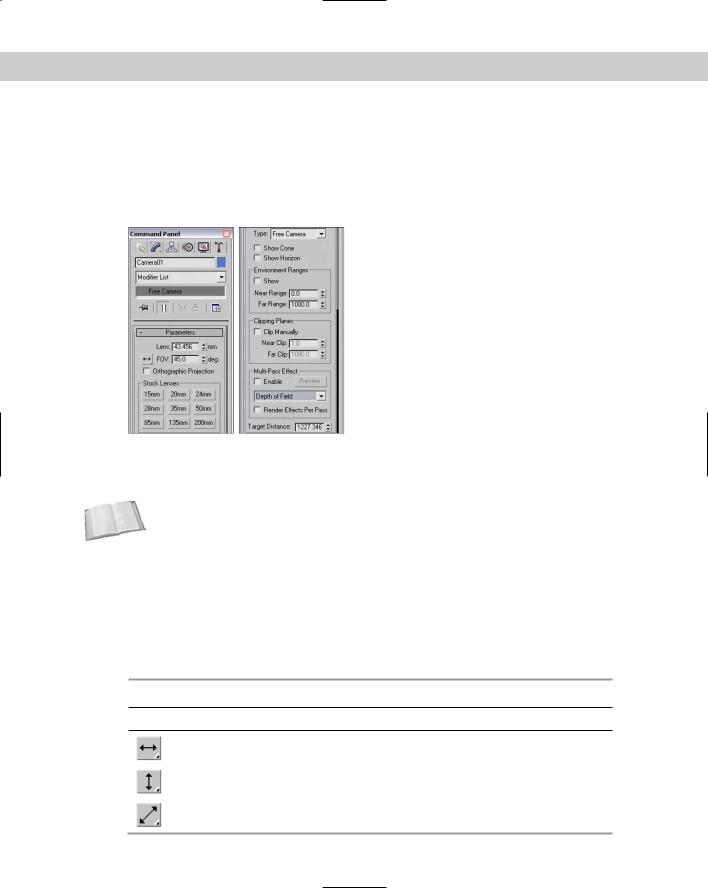
When a camera is first created, you can modify the camera parameters directly in the Create panel as long as the new camera is selected. After the camera object has been deselected, you can make modifications in the Modify panel’s Parameters rollout for the camera, shown in Figure 24-5.
Figure 24-5: The Parameters rollout (shown in two parts) lets you specify Lens values
or choose from a selection of stock lenses.
Cross- |
Multi-pass cameras can be set up to create Depth of Field and Motion Blur effects. These |
Reference |
effects are covered in Chapter 26, “Multi-Pass Camera Effects.” |
|
Lens settings and field of view
The first parameter in the Parameters rollout sets the Lens value or more simply, the camera’s focal length in millimeters.
The second parameter, FOV (which stands for field of view), sets the width of the area that the camera displays. The value is specified in degrees and can be set to represent a Horizontal, Vertical, or Diagonal distance using the flyout button to its left, as shown in Table 24-2.
|
Table 24-2: Field of View Buttons |
Button |
Description |
|
Horizontal distance |
|
Vertical distance |
|
Diagonal distance |
662 Part V Cameras
The Orthographic Projection option displays the camera view in a manner similar to any of the orthographic viewports such as Top, Left, or Front. This eliminates any perspective distortion of objects farther back in the scene and displays true dimensions for all edges in the scene.
Professional photographers and film crews use standard stock lenses in the course of their work. These lenses can be simulated in Max by clicking one of the Stock Lens buttons. Preset stock lenses include 15, 20, 24, 28, 35, 50, 85, 135, and 200mm lengths. The Lens and FOV fields are automatically updated on stock lens selection.
Tip |
On cameras that use 35mm film, the typical default lens is 50mm. |
Camera type and display options
The Type option enables you to change a Free camera to a Target camera and back at any time.
The Show Cone option enables you to display the camera’s cone, showing the boundaries of the camera view when the camera isn’t selected. (The camera cone is always visible when a camera is selected.) The Show Horizon option sets a horizon line within the camera view, which is a dark gray line where the horizon is located.
Environment ranges and clipping planes
You use the Near and Far Range values to specify the volume within which atmospheric effects like fog and volume lights are to be contained. The Show option causes these limits to be displayed as yellow rectangles within the camera’s cone.
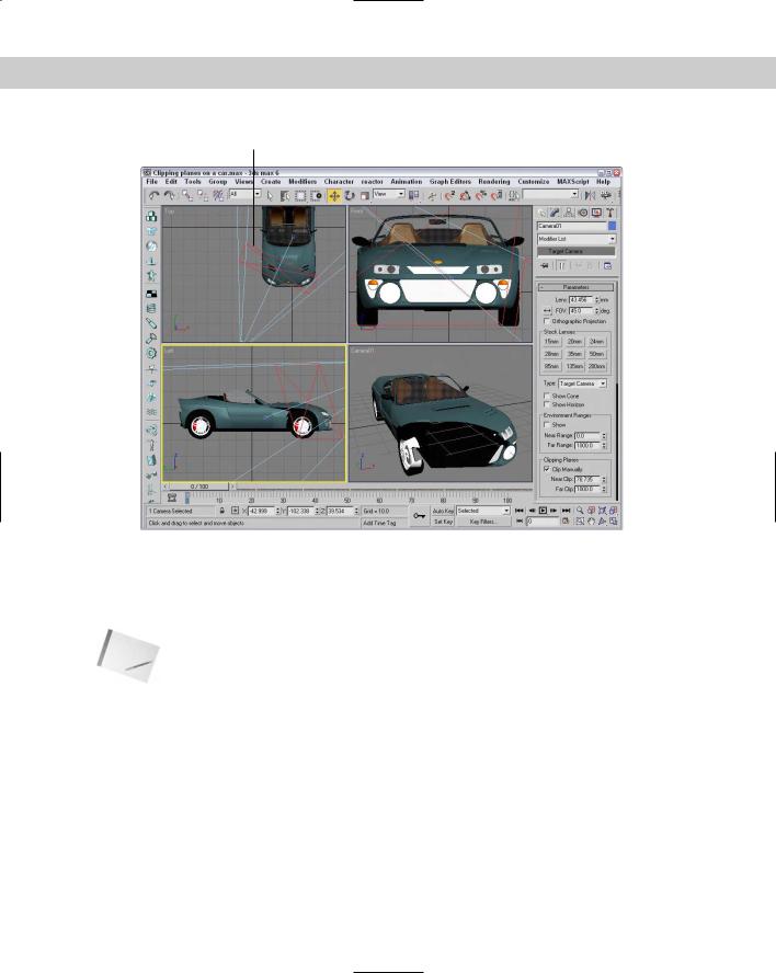
You use clipping planes to designate the closest and farthest object that the camera can see. In Max, they are displayed as red rectangles with crossing diagonals in the camera cone. The Clip Manually option lets you specify the Near Clip Plane to be something less than three units. Figure 24-6 shows a camera with Clipping Planes specified. The front Clipping Plane intersects the car and chops off its front end. The far Clipping Plane intersects the middle of the car and clips the back-end of the car as well as the construction grid.
Tip |
Clipping planes can be used to create a cutaway view of your model. |
Camera Correction Modifier
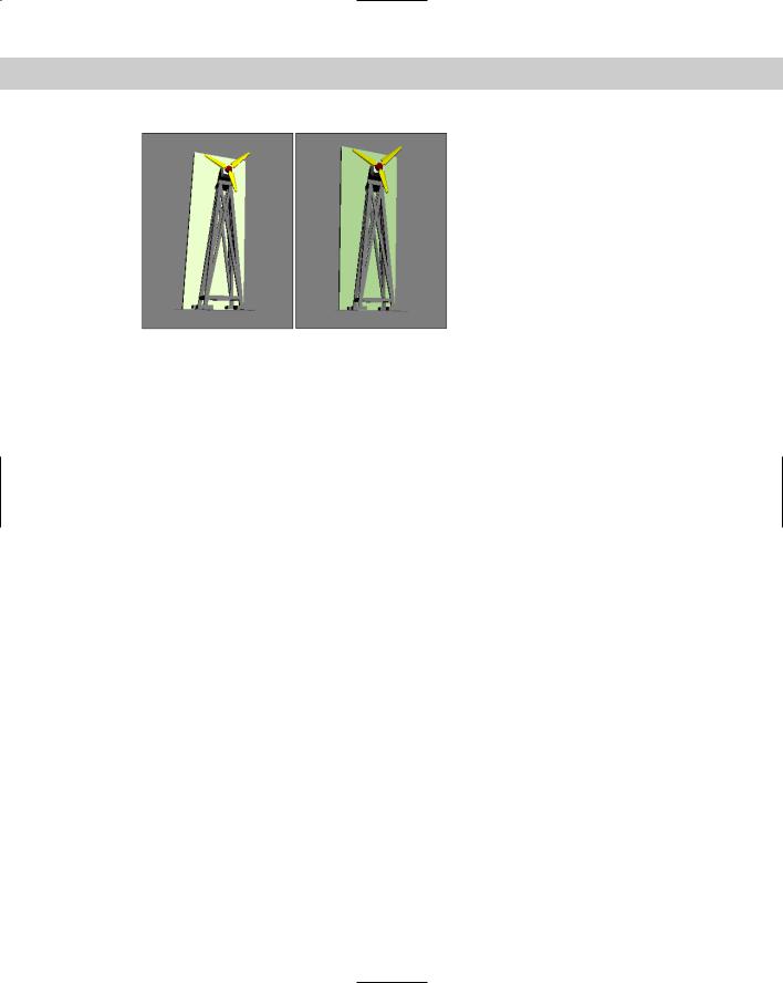
To understand the Camera Correction modifier, you first need to understand what 2-point perspective is. Default cameras in Max use 3-point perspective, which causes all lines to converge to a vanishing point off in the distance, but 2-point perspective causes all vertical lines to remain vertical.
The visual effect of this modifier is that extra tall objects appear to bend toward the camera when corrected. For example, if you have a camera pointed at a skyscraper, then correcting the camera with the Camera Correction modifier makes the top of the building appear closer rather than having it recede away.
Chapter 24 Working with Cameras 663
Near clipping plane
Figure 24-6: A camera cone displaying Clipping Planes
The Camera Correction modifier has an Amount value that lets you specify how much correction to apply and a Direction value that orients the angle of vertical lines in the scene. There is also a Guess button, which automatically sets the correction values for you based on the Z axis vertical.
Note |
The Camera Correction modifier doesn’t appear in the Modifier List in the Modifier Stack, but |
|
you can select it from the Modifiers menu. |
Figure 24-7 shows a windmill object with a simple Box positioned behind it. In the left image, notice that the windmill recedes away from the camera, which is positioned at the base of the windmill, but the right image has been camera corrected.
664 Part V Cameras
Figure 24-7: Applying the Camera Correction modifier reorients the camera perspective.
Summary
Cameras can offer a unique look at your scene. You can position and move them anywhere. In this chapter, you discovered how cameras work and how to control and aim them at objects.
The Camera Match and Camera Tracker utilities enable you to match your scene’s position and motion to a background image or animation. These features can be very helpful in creating realistic images and animations.
In this chapter, you’ve
Learned the basics of cameras
Created a camera object and view
Discovered how to control a camera
Aimed a camera at objects
Changed camera parameters
Learned to correct camera perspective with the Camera Correction modifier
The next chapter deals with matching a camera to the perspective of a background image and tracking a camera’s movement for a background animation.
|
|
|
Matching and
Tracking Cameras
At times you’ll want to integrate your rendered images with an existing background image or a background animation
sequence. To do this, Max includes two unique utilities — Camera Match and Camera Tracker. The Camera Match utility can fit rendered scenes into an existing background image by matching the camera’s position to the perspective of the image. The Camera Tracker utility can reproduce a camera’s motion using an animated background.
Matching a Camera to a
Background Image
You use the Camera Match tool to align a camera’s position to the background image. After you align the camera to the position that was used to take the image, you can place 3D objects within your scene and be assured that they will line up correctly with the objects within the image. For example, if you take a picture of a street scene and align the camera with the background image, then any cars or buildings that you digitally add to the scene are correctly aligned.
You can find the Camera Match tool in the Utilities panel. Before you can use this tool, you need to load a bitmap image as a background. To do so, open the Environment dialog box by choosing Rendering Environment (or by pressing the 8 key).
Cross- |
Chapter 41, “Rendering Basics,” provides more details on loading |
Reference |
and working with environment maps. |
|
After a bitmap image loads as an environment map, make the background visible in the viewport by choosing Views Viewport Background (Alt+B) to open the Viewport Background dialog box. Here, you can specify a background source image or use the environment map you just loaded.
Setting Camera Match points
25C H A P T E R
In This Chapter
Using the Camera Match utility to match a camera to the background image
Tracking animation points with the Camera Tracker utility
After a background image loads and is visible in the viewport, you need to create Camera Points in the scene. These Camera Points
666 Part V Cameras
identify specific locations within the bitmap and help match them to scene dimensions. To create the Camera Points, select Create Helpers Camera Point.
The Camera Match utility needs to have at least five Camera Points defined before it can create a camera. You should position these Camera Points in the scene at precise coordinates that match the background image. For example, if the distance between two points is four feet, then create the Camera Points such that they are four units from each other. In the Keyboard Entry rollout, you can create new Camera Points by entering exact XYZ values.
Note |
To help keep the Camera Points straight, you can name each Camera Point by typing a name |
|
in the Name field. This helps when you try to identify each point in the Camera Match utility. |
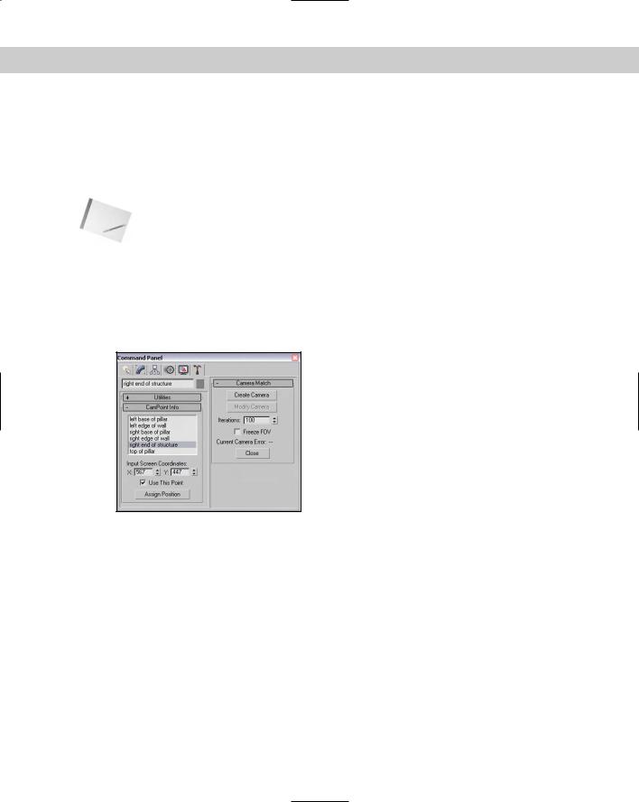
After positioning the Camera Points, open the Utilities panel and click the Camera Match button in the Utilities rollout. The Camera Point Info rollout, shown in Figure 25-1, includes a list of Camera Points. Each Camera Point needs to be assigned an XY position that matches its 3D location to a 2D position on the background bitmap. To assign these positions, click the Assign Position button, select a Camera Point from the list, and click the location in the viewport where this point should be positioned. You can also enter the X and Y coordinate values for the selected position in the X and Y fields in the Camera Point Info rollout.
Figure 25-1: After the position of each Camera Point is identified, you can create a camera.
As you line up the Camera Point positions, the bottom of the Camera Match rollout shows the current camera error. If the error value is greater than 5, the camera can’t be created. The Use This Point option can disable a Camera Point without deleting it, which can help you pinpoint the Camera Point that is misaligned.
The Create Camera button creates a camera after all the Camera Points have been correctly positioned. The Modify Camera button lets you realign Camera Points and change the current camera position. The Iterations value determines the number of calculations required to position the camera; if your error values are too high, try reducing this number and creating the camera again. The Freeze FOV (field of view) option prevents the FOV from changing as a camera is created.
Chapter 25 Matching and Tracking Cameras 667
Tutorial: Driving in Rome
The streets of Rome are narrow and intricate — maybe because they need to wind around all the ancient structures. In this tutorial, those streets provide a perfect opportunity to practice using the Camera Match utility.
To match a camera view to a background image, follow these steps:
1.Open the Rome – matched camera.max file from the Chap 25 directory on the CD-ROM.
This file has the background image already loaded and visible in the viewport. This file also has the Porsche model created by Viewpoint Datalabs imported.
2.Now assign Camera Points throughout the scene. Select Create Helpers Camera Points and click in the Perspective view six times to create six Camera Points. Then select the first Camera Point, and click the Select and Move button (W). Then open the Move Transform Type-In dialog box by choosing Tools Transform Type-In (or by pressing the F12 key). Give the Camera Points the names and dimensions in the following list. Enter the dimensions in the Absolute column on the left.
•Left base of pillar: X = 0, Y = 0, Z = 0
•Right base of pillar: X = 10, Y = 0, Z = 0
•Left edge of wall: X = –10, Y = 0, Z = 0
•Right edge of wall: X = 20, Y = 0, Z = 0
•Right end of structure: X = 0, Y = 20, Z = 0
•Top of pillar: X = 0, Y = 0, Z = 30
Note Although accurate measurements are better, these dimensions are relative approximations (because I didn’t have time to fly to Rome with a tape measure).
3.After you position the six Camera Points, click the Camera Match button in the Utilities panel. In the Camera Point rollout is a list of the Camera Points that you’ve created. For each Camera Point in the list, click the Assign Position button, select the point, and click the background image where it is located. The following list has the exact dimensions that you can use to check your placement. When you’re finished, click the Assign Position button again to exit position selection mode.
•Left base of pillar: X = 279, Y = 324
•Right base of pillar: X = 322, Y = 346
•Left edge of wall: X = 236, Y = 306
•Right edge of wall: X = 372, Y = 370
•Right end of structure: X = 358, Y = 305
•Top of pillar: X = 278, Y = 144
4.After you’ve positioned all Camera Points, click the Create Camera button. If the current camera error value is less than 5, a camera appears in the scene. You can update the Camera Point positions by clicking the Assign Position button, selecting a Camera