

- •Preface
- •About This Book
- •Acknowledgments
- •Contents at a Glance
- •Contents
- •Relaxing at the Beach
- •Dressing the Scene
- •Animating Motion
- •Rendering the Final Animation
- •Summary
- •The Interface Elements
- •Using the Menus
- •Using the Toolbars
- •Using the Viewports
- •Using the Command Panel
- •Using the Lower Interface Bar Controls
- •Interacting with the Interface
- •Getting Help
- •Summary
- •Understanding 3D Space
- •Using the Viewport Navigation Controls
- •Configuring the Viewports
- •Working with Viewport Backgrounds
- •Summary
- •Working with Max Scene Files
- •Setting File Preferences
- •Importing and Exporting
- •Referencing External Objects
- •Using the File Utilities
- •Accessing File Information
- •Summary
- •Customizing Modify and Utility Panel Buttons
- •Working with Custom Interfaces
- •Configuring Paths
- •Selecting System Units
- •Setting Preferences
- •Summary
- •Creating Primitive Objects
- •Exploring the Primitive Object Types
- •Summary
- •Selecting Objects
- •Setting Object Properties
- •Hiding and Freezing Objects
- •Using Layers
- •Summary
- •Cloning Objects
- •Understanding Cloning Options
- •Mirroring Objects
- •Cloning over Time
- •Spacing Cloned Objects
- •Creating Arrays of Objects
- •Summary
- •Working with Groups
- •Building Assemblies
- •Building Links between Objects
- •Displaying Links and Hierarchies
- •Working with Linked Objects
- •Summary
- •Using the Schematic View Window
- •Working with Hierarchies
- •Setting Schematic View Preferences
- •Using List Views
- •Summary
- •Working with the Transformation Tools
- •Using Pivot Points
- •Using the Align Commands
- •Using Grids
- •Using Snap Options
- •Summary
- •Exploring the Modifier Stack
- •Exploring Modifier Types
- •Summary
- •Exploring the Modeling Types
- •Working with Subobjects
- •Modeling Helpers
- •Summary
- •Drawing in 2D
- •Editing Splines
- •Using Spline Modifiers
- •Summary
- •Creating Editable Mesh and Poly Objects
- •Editing Mesh Objects
- •Editing Poly Objects
- •Using Mesh Editing Modifiers
- •Summary
- •Introducing Patch Grids
- •Editing Patches
- •Using Modifiers on Patch Objects
- •Summary
- •Creating NURBS Curves and Surfaces
- •Editing NURBS
- •Working with NURBS
- •Summary
- •Morphing Objects
- •Creating Conform Objects
- •Creating a ShapeMerge Object
- •Creating a Terrain Object
- •Using the Mesher Object
- •Working with BlobMesh Objects
- •Creating a Scatter Object
- •Creating Connect Objects
- •Modeling with Boolean Objects
- •Creating a Loft Object
- •Summary
- •Understanding the Various Particle Systems
- •Creating a Particle System
- •Using the Spray and Snow Particle Systems
- •Using the Super Spray Particle System
- •Using the Blizzard Particle System
- •Using the PArray Particle System
- •Using the PCloud Particle System
- •Using Particle System Maps
- •Controlling Particles with Particle Flow
- •Summary
- •Understanding Material Properties
- •Working with the Material Editor
- •Using the Material/Map Browser
- •Using the Material/Map Navigator
- •Summary
- •Using the Standard Material
- •Using Shading Types
- •Accessing Other Parameters
- •Using External Tools
- •Summary
- •Using Compound Materials
- •Using Raytrace Materials
- •Using the Matte/Shadow Material
- •Using the DirectX 9 Shader
- •Applying Multiple Materials
- •Material Modifiers
- •Summary
- •Understanding Maps
- •Understanding Material Map Types
- •Using the Maps Rollout
- •Using the Map Path Utility
- •Using Map Instances
- •Summary
- •Mapping Modifiers
- •Using the Unwrap UVW modifier
- •Summary
- •Working with Cameras
- •Setting Camera Parameters
- •Summary
- •Using the Camera Tracker Utility
- •Summary
- •Using Multi-Pass Cameras
- •Creating Multi-Pass Camera Effects
- •Summary
- •Understanding the Basics of Lighting
- •Getting to Know the Light Types
- •Creating and Positioning Light Objects
- •Viewing a Scene from a Light
- •Altering Light Parameters
- •Working with Photometric Lights
- •Using the Sunlight and Daylight Systems
- •Using Volume Lights
- •Summary
- •Selecting Advanced Lighting
- •Using Local Advanced Lighting Settings
- •Tutorial: Excluding objects from light tracing
- •Summary
- •Understanding Radiosity
- •Using Local and Global Advanced Lighting Settings
- •Working with Advanced Lighting Materials
- •Using Lighting Analysis
- •Summary
- •Using the Time Controls
- •Working with Keys
- •Using the Track Bar
- •Viewing and Editing Key Values
- •Using the Motion Panel
- •Using Ghosting
- •Animating Objects
- •Working with Previews
- •Wiring Parameters
- •Animation Modifiers
- •Summary
- •Understanding Controller Types
- •Assigning Controllers
- •Setting Default Controllers
- •Examining the Various Controllers
- •Summary
- •Working with Expressions in Spinners
- •Understanding the Expression Controller Interface
- •Understanding Expression Elements
- •Using Expression Controllers
- •Summary
- •Learning the Track View Interface
- •Working with Keys
- •Editing Time
- •Editing Curves
- •Filtering Tracks
- •Working with Controllers
- •Synchronizing to a Sound Track
- •Summary
- •Understanding Your Character
- •Building Bodies
- •Summary
- •Building a Bones System
- •Using the Bone Tools
- •Using the Skin Modifier
- •Summary
- •Creating Characters
- •Working with Characters
- •Using Character Animation Techniques
- •Summary
- •Forward versus Inverse Kinematics
- •Creating an Inverse Kinematics System
- •Using the Various Inverse Kinematics Methods
- •Summary
- •Creating and Binding Space Warps
- •Understanding Space Warp Types
- •Combining Particle Systems with Space Warps
- •Summary
- •Understanding Dynamics
- •Using Dynamic Objects
- •Defining Dynamic Material Properties
- •Using Dynamic Space Warps
- •Using the Dynamics Utility
- •Using the Flex Modifier
- •Summary
- •Using reactor
- •Using reactor Collections
- •Creating reactor Objects
- •Calculating and Previewing a Simulation
- •Constraining Objects
- •reactor Troubleshooting
- •Summary
- •Understanding the Max Renderers
- •Previewing with ActiveShade
- •Render Parameters
- •Rendering Preferences
- •Creating VUE Files
- •Using the Rendered Frame Window
- •Using the RAM Player
- •Reviewing the Render Types
- •Using Command-Line Rendering
- •Creating Panoramic Images
- •Getting Printer Help
- •Creating an Environment
- •Summary
- •Creating Atmospheric Effects
- •Using the Fire Effect
- •Using the Fog Effect
- •Summary
- •Using Render Elements
- •Adding Render Effects
- •Creating Lens Effects
- •Using Other Render Effects
- •Summary
- •Using Raytrace Materials
- •Using a Raytrace Map
- •Enabling mental ray
- •Summary
- •Understanding Network Rendering
- •Network Requirements
- •Setting up a Network Rendering System
- •Starting the Network Rendering System
- •Configuring the Network Manager and Servers
- •Logging Errors
- •Using the Monitor
- •Setting up Batch Rendering
- •Summary
- •Compositing with Photoshop
- •Video Editing with Premiere
- •Video Compositing with After Effects
- •Introducing Combustion
- •Using Other Compositing Solutions
- •Summary
- •Completing Post-Production with the Video Post Interface
- •Working with Sequences
- •Adding and Editing Events
- •Working with Ranges
- •Working with Lens Effects Filters
- •Summary
- •What Is MAXScript?
- •MAXScript Tools
- •Setting MAXScript Preferences
- •Types of Scripts
- •Writing Your Own MAXScripts
- •Learning the Visual MAXScript Editor Interface
- •Laying Out a Rollout
- •Summary
- •Working with Plug-Ins
- •Locating Plug-Ins
- •Summary
- •Low-Res Modeling
- •Using Channels
- •Using Vertex Colors
- •Rendering to a Texture
- •Summary
- •Max and Architecture
- •Using AEC Objects
- •Using Architectural materials
- •Summary
- •Tutorial: Creating Icy Geometry with BlobMesh
- •Tutorial: Using Caustic Photons to Create a Disco Ball
- •Summary
- •mental ray Rendering System
- •Particle Flow
- •reactor 2.0
- •Schematic View
- •BlobMesh
- •Spline and Patch Features
- •Import and Export
- •Shell Modifier
- •Vertex Paint and Channel Info
- •Architectural Primitives and Materials
- •Minor Improvements
- •Choosing an Operating System
- •Hardware Requirements
- •Installing 3ds max 6
- •Authorizing the Software
- •Setting the Display Driver
- •Updating Max
- •Moving Max to Another Computer
- •Using Keyboard Shortcuts
- •Using the Hotkey Map
- •Main Interface Shortcuts
- •Dialog Box Shortcuts
- •Miscellaneous Shortcuts
- •System Requirements
- •Using the CDs with Windows
- •What’s on the CDs
- •Troubleshooting
- •Index
494 Part III Modeling
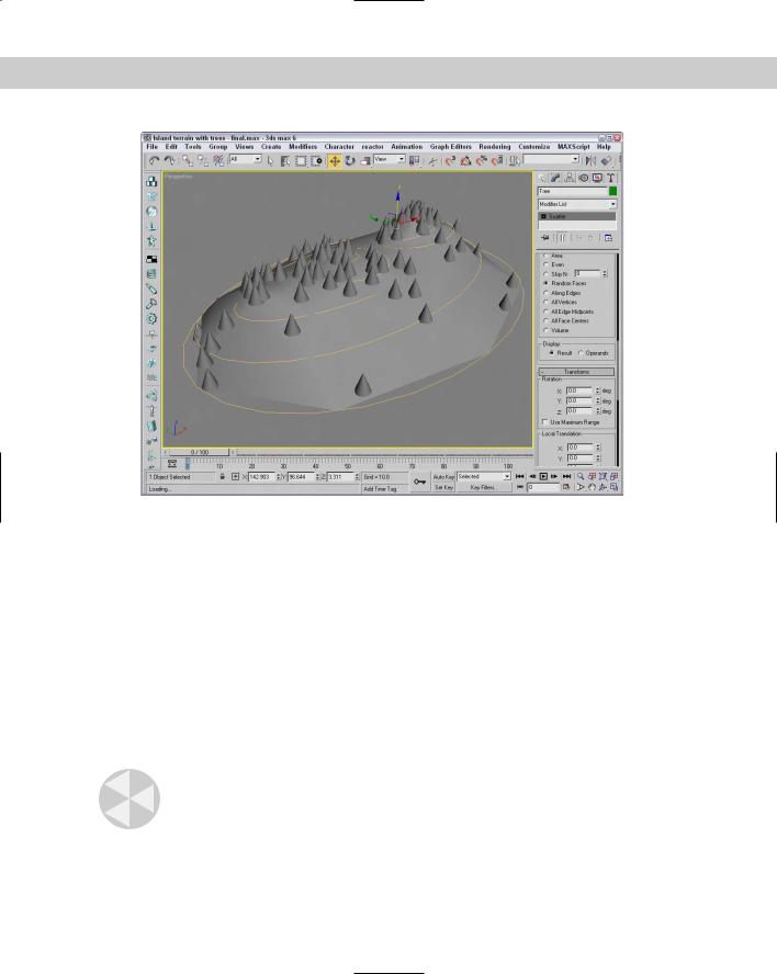
Figure 17-17: Using the Scatter object, we can add trees to our island terrain.
Creating Connect Objects
A Connect object is useful for building a connecting bridge between two separate objects. Each object must have an open face or hole that specifies where the two objects are to be connected.
To use this object, delete a face on two Editable Mesh objects and then position the holes across from each other. Select one of the objects and choose Create Compound Connect menu command. Then, click the Pick Operand button, and select the second object. The Connect object builds the additional faces required to connect the two holes.
Filling object holes
If multiple holes exist between the objects, the Connect object attempts to patch them all. You can also use the button several times to connect a single object to multiple objects.
Caution |
The Connect object doesn’t work well with NURBS objects. |
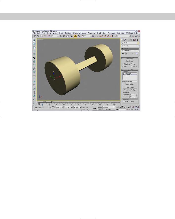
Figure 17-18 shows a normal Connect object without any smoothing options.
Chapter 17 Building Compound Objects 495
Figure 17-18: Two cylinders connected using the Connect object
The Parameters rollout includes a list of all the operands or objects involved in the connection. You can delete any of these with the Delete Operand button. The Extract Operand button lets you separate the Operand object from the Connect object.
In the Interpolation section, the Segments value is the number of segments used to create the bridge section, and the Tension value is the amount of curvature to use in an attempt to smooth the connected bridge.
The Bridge Smoothing option smoothes the faces of the bridge, and the Ends option smoothes where the bridge and the original objects connect.
Tutorial: Creating a park bench
The Connect object is best used between two symmetrical copies of an object that need to be attached, as with a table or bridge. For this tutorial, we use the Connect object to create a park bench between two end pieces.
To connect two ends of a park bench, follow these steps:
1.Open the Park bench.max file from the Chap 17 directory on the CD-ROM.
This file includes symmetrical ends of the park bench. One end was created by extruding a spline shape and using the ShapeMerge tool to cut matching holes on the inner facing surfaces. The Mirror tool was then used to create and rotate the symmetrical clone.
496 Part III Modeling
2.Select one end of the park bench, and select the Create Compound Connect menu command.
3.In the Pick Operand rollout, click the Pick Operand button, select the Move option, and click on the opposite side of the park bench.
The two end pieces connect.
4.In the Parameters rollout, select the Smoothing: Bridge option to smooth the seat of the bench.
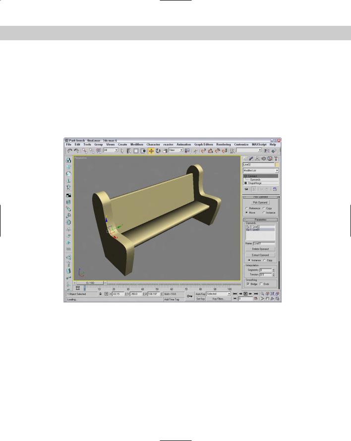
Figure 17-19 shows the resulting park bench.
Figure 17-19: A Connect compound object can join two open holes in separate objects.
Modeling with Boolean Objects
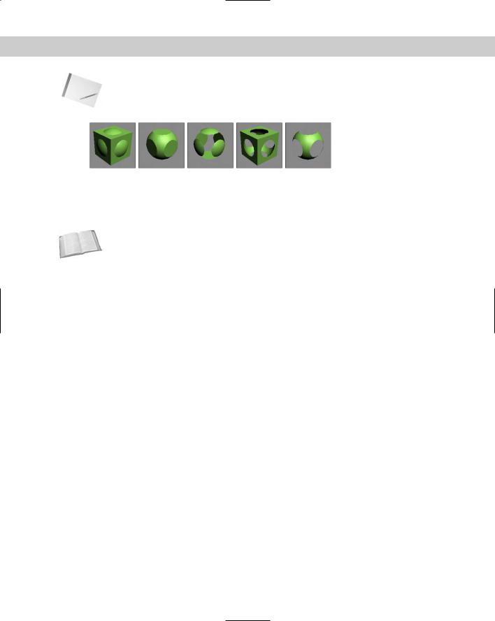
When two objects overlap, you can perform different Boolean operations on them to create a unique object. The Boolean operations include Union, Subtraction, Intersection, and Cut. The Union operation combines two objects into one. The Subtraction operation subtracts the overlapping portions of one object from another. The Intersection operation retains only the overlapping sections of two objects, and the Cut operation can cut an object like the Subtraction operator does, while letting the cut piece remain. Figure 17-20 shows each of the possible Boolean operators.
Chapter 17 Building Compound Objects 497
Note Unlike many CAD packages that deal with solid objects, Max’s Booleans are applied to surfaces, so if the surfaces of the two objects don’t overlap, the Boolean operation has no effect.
Figure 17-20: Boolean operations: Union, Intersection, Subtraction (A-B), Subtraction (B-A), and Cut: Remove Inside
All Boolean operations are layered in the Stack. You can revisit an operation at any time and make changes to it.
Cross- You can also apply Boolean operations to shapes using the Boolean operators available for Reference Editable Meshes in the Geometry rollout. Chapter 13, “Drawing and Editing 2D Splines and
Shapes,” covers these 2D Boolean operators.
Union
The Union operation combines two objects into one. To Union two objects, select an object and click the Boolean button. Under the Parameters rollout, the selected object is referred to as Operand A. In the Pick Operand rollout, click the Pick Operand B button and select a second object in the viewport. (Operand B can be a Copy, Instance, Reference, or Move object.) To apply the Boolean operation, click the Union option.
Intersection
The Intersection operation creates an object from the overlapping sections of two objects. For this operation, like the Union operation, which object is A and which is B isn’t important.
Subtraction
The Subtraction operation subtracts the overlapping portions of one object from the other. For this operation, the order in which the objects are selected is important. Subtracting object A from object B gives you a different object from what you get when you subtract object B from object A.
Cut
The Cut operation is similar to the Slice modifier, except that it uses another object instead of a slice plane gizmo, and only Operand A is modified in the process. The Cut operation has several options, including Refine, Split, Remove Inside, and Remove Outside.

498 Part III Modeling
The Refine option marks the selected object with new edges where it intersects Operand B. The Split option actually divides the mesh object into separate elements.
The Remove Inside and Remove Outside options are variations of the Split option. They remove the inner or outer portion of the object. These options work like the Subtraction and Intersection options, except that the Cut operation leaves holes in the base geometry.
Tips for working with Booleans
Working with Boolean objects can be difficult. If you try to perform a Boolean operation on an ill-suited object, the results could end up being erratic. As you prepare objects for Boolean operations, keep the following points in mind:
Avoid meshes with long, skinny polygon faces. All faces should have roughly equal lengths and widths. The ratio of edge length to width should be less than 4 to 1.
Avoid curved lines where possible. Curved lines have the potential of folding back on themselves, which causes problems. If you need to use a curve, try not to intersect it with another curve; keep the curvature to a minimum.
Unlink any objects not involved in the Boolean operation. Linked objects, even if they don’t intersect, can cause problems.
If you’re having difficulty getting a Boolean operation to work, try applying the XForm modifier (found in the Modifiers List) to combine all the transformations into one. Then collapse the Stack, and convert the objects to Editable Mesh objects. This technique removes any modifier dependencies.
Make sure that your objects are completely closed surfaces with no holes, overlapping faces, or unwelded vertices. You can check these criteria by applying the STL-Check modifier or by looking at all sides of the objects in a viewport with Smooth Shading enabled.
Make sure that all surface normals are consistent — inconsistent normals cause unexpected results. You can use the Normal modifier to unify and flip all normals on an object. The Show Normals option in the viewport can also help.
Collapsing the Stack after all Boolean operations have been performed eliminates dependencies on the previous object types.
Tutorial: Creating a Lincoln Log set
In the household where I grew up, we had sets of Legos and a lesser-known construction set known as Lincoln Logs that let you to create buildings using notched logs that fit together. Using a Subtraction operation, you can create your own virtual set of Lincoln Logs.
Cross- |
This tutorial transforms objects and uses the Array dialog box. You can find information about |
Reference |
transforming objects in Chapter 10, “Transforming Objects — Translate, Rotate, and Scale.” |
|

Chapter 17 Building Compound Objects 499
To use Boolean objects to create a log cabin, follow these steps:
1.Open the Lincoln logs booleans.max from the Chap 17 directory on the CD-ROM. This file contains some simple primitives.
2.Select the Cylinder object, and choose the Create Compound Boolean menu command. In the Operation section, select the Subtraction (A–B) option. Then in the Pick Boolean rollout, click the Pick Operand B button and select one of the Box objects.
3.Repeat the Subtraction operation on the other three boxes by right clicking in the active viewport and performing Step 3 again.
When finished, you should have a cylinder with four notches.
Note |
If you simply click the Pick Operand B button again, the first notch is replaced by the second |
|
operation. |
4.Clone the single log by choosing Edit Clone and then selecting the Copy option. Move the cloned log along the negative Y axis a distance of 160. The easiest way to do so is to select the Select and Move button and right-click it to open the Move Transform TypeIn dialog box. In the Absolute World field, enter –160 as the Y-axis value.
This step positions two logs next to one another to form the bottom layer of the house.
5.Select both logs, and open the Array dialog box by choosing Tools Array. In the Incremental Move row, enter 10 for the Z axis. In the Incremental Rotate row, enter 90 for the Z axis. In the Array Dimensions section, enter a Count value of 16. Click the OK button.
This step stacks several layers of logs.
6.Select one log, and use the right-click pop-up menu to convert that log to an Editable Mesh. Open the Modify panel, click the Attach button, and then select every log to combine them all into a single object. Click the Attach button again to exit attach mode when you’re finished.
7.Select the Create Standard Primitives Box menu command, and create a Box object with the following dimensions: Length of 40, Width of 40, and Height of 80. Then position the Box in the Top viewport where the front door should be.
8.Return to the Compound Objects subcategory, select the logs, and click the Boolean button. Then click the Pick Operand B button again, and select the Box.
The rollout remembers and retains the last options selected, including the Subtract (A –B) operation.
9.To add a roof, select the Extended Primitives subcategory and click the Prism button. Drag in the Left view to create a prism object that covers the logs.
Figure 17-21 shows our Boolean log cabin, ready for the virtual pioneers.