

Chapter 10 Transforming Objects—Translate, Rotate, and Scale |
271 |
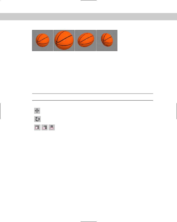
Figure 10-1: These basketballs have been scaled using uniform, non-uniform, and squash modes.
Using the transform buttons
The three transform buttons located on the main toolbar are Select and Move, Select and Rotate, and Select and Uniform Scale, as shown in Table 10-1. Using these buttons, you can select objects and transform them by dragging in one of the viewports with the mouse. You can access these buttons using three of the big four keyboard shortcuts — Q for Select Objects, W for Select and Move, E for Select and Rotate, and R for Select and Scale.
Table 10-1: Transform Buttons
Toolbar Button |
Name |
Description |
|
|
|
|
Select and Move (W) |
Enters move mode where clicking and |
|
|
dragging an object moves it. |
|
Select and Rotate (E) |
Enters rotate mode where clicking and |
|
|
dragging an object rotates it. |
|
Select and Uniform Scale (R), |
Enters scale mode where clicking and |
|
Select and Non-Uniform Scale, |
dragging an object scales it. |
|
Select and Squash |
|
|
|
|
Working with the Transformation Tools
To help you in your transformations, you can use several tools to transform objects (and you don’t even need a phone booth). These tools include the Transform Gizmos, the Transform Type-In dialog box (F12), Status Bar transform fields, and the Transform Managers.
Working with the Transform Gizmos
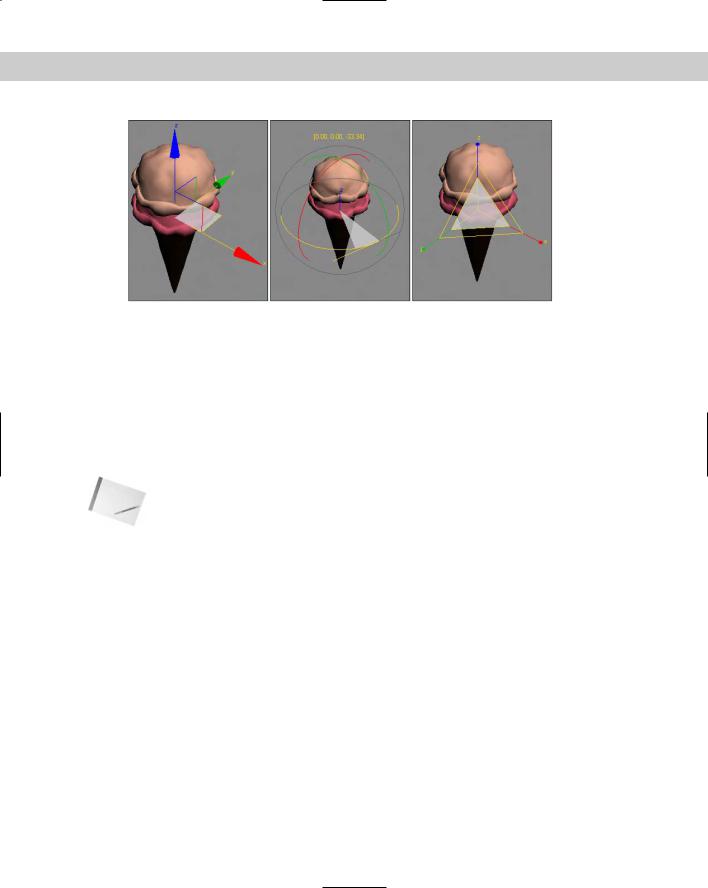
The Transform Gizmos appear at the center of the selected object (actually at the object’s pivot point) when you click one of the transform buttons. The type of gizmo that appears depends on the transformation mode that is selected. You can choose from three different gizmos, one for each transformation type. Each gizmo includes three color-coded arrows, circles, and lines representing the X-, Y-, and Z-axes. The X-axis is colored red, the Y-axis is colored green, and the Z-axis is colored blue. Figure 10-2 shows the gizmos for each of the transformation types — move, rotate, and scale.
272 Part II Working with Objects
Figure 10-2: The Transform Gizmos lets you constrain a transformation to a single axis or a plane.
If the Transform Gizmo is not visible, you can enable it by choosing Views Show Transform Gizmo or by pressing the X key to toggle it on and off. You can use the – (minus) and = (equals) keys to decrease or increase the gizmo’s size.
Using the interactive gizmos
Moving the cursor over the top of one of the Transform Gizmo’s axes in the active viewport selects the axis, which changes to yellow. Dragging the selected axis restricts the transformation to that axis only. For example, selecting the red X axis on the Move Gizmo and dragging moves the selected object along only the X axis.
Note The transformation gizmos provide an alternate (and visual) method for constraining transformations along an axis or plane. This reduces the need for the Axis Constraint buttons, which have been removed to a separate floating toolbar. Learning to use these gizmos is well worth the time.
The Move Gizmo
In addition to the arrows for each axis, in each corner of the Move Gizmo are two perpendicular lines for each plane. These lines let you transform along two axes simultaneously. The colors of these lines match the various colors used for the axes. For example, in the Perspective view, dragging on a red and blue corner would constrain the movement to the XZ plane.
Selecting one of these lines highlights it. At the center of the Move Gizmo is a Center Box that marks the pivot point’s origin.
The Rotate Gizmo
The Rotate Gizmo surrounds the selected object in a sphere. A colored line for each axis circles the surrounding sphere. As you select an axis and drag, an arc is highlighted that shows the distance of the rotation along that axis and the offset value is displayed in text above the object. Clicking on the sphere away from the axes lets you rotate the selected object in all directions.
Chapter 10 Transforming Objects—Translate, Rotate, and Scale |
273 |
The Scale Gizmo
The Scale Gizmo consists of two triangles and a line for each axis. Selecting and dragging the center triangle uniformly scales the entire object. Selecting a slice of the outer triangle scales the object along the adjacent two axes, and dragging on the axis lines scales the object in a non-uniform manner along a single axis.
Setting Gizmo preferences
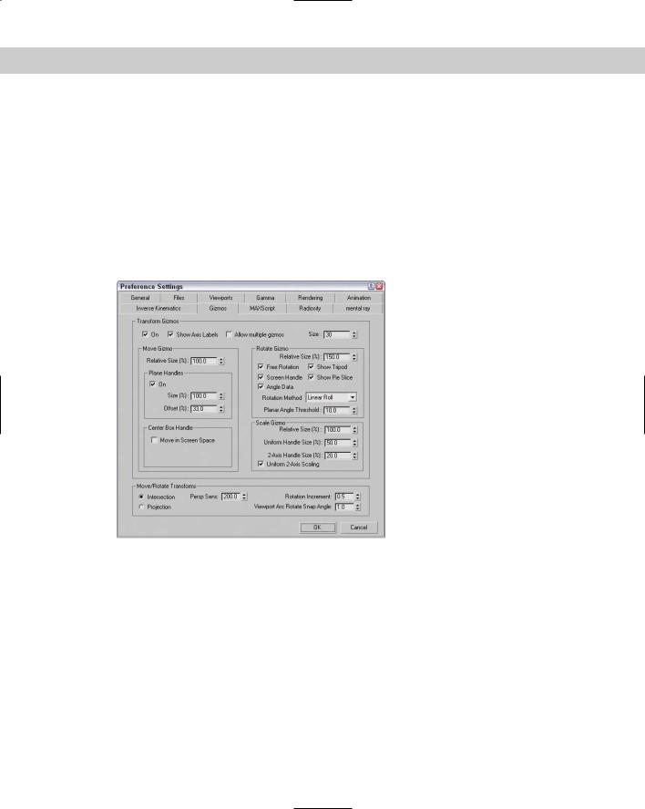
For each of these gizmos, you can set the preferences using the Gizmos panel in the Preference Settings dialog box, shown in Figure 10-3. In this panel for all gizmos, you can turn the gizmos on or off, set to Show Axis Labels, Allow Multiple Gizmos, and set the Size of the gizmo’s axes. The Allow Multiple Gizmos option enables a separate gizmo for each selection set object. The Labels option labels each axis with an X, Y, or Z.
Figure 10-3: The Gizmos panel in the Preference Settings dialog box lets you control how the transform gizmos look.
For the Move Gizmo section, you can set the Relative Size of the gizmo, which is relative to the top Size value, so a setting of 100% makes the size of the gizmo a full 30 and a setting a 50% makes it 15, or half the full Size value. You can also select to turn the plane handles on or off and set their Size and Offset values, which determine how large the highlighted planes are and where they are located relative to the center of the gizmo. A Size value of 100% extends the plane handles to be as long as the axis handles. You can also enable the Center Box Handle for moving in all three axes.
The Rotate Gizmo preferences also include a Relative Size value. The Free Rotation option enables you to click and drag between the axes to rotate the object freely along all axes. The

274 Part II Working with Objects
Show Tripod option displays the axes tripod at the center of the object. The Screen Handle option displays an additional gray circle that surrounds all the axes. Dragging on this handle spins the object about the viewport’s center. The Show Pie Slide highlights a slice along the selected axis that is as big as the offset distance. The Angle Data option displays the rotation values above the gizmo as it’s being rotated.
The Gizmos panel offers three different Rotation Methods: Linear Roll, Circular Crank, and Legacy R4. The Linear Roll method displays a tangent line at the source point where the rotation starts. The Circular Cranks method rotates using the gizmo axes that surround the object. The Legacy R4 method uses a gizmo that looks just like the Move Gizmo that was available in the previous Max version. The Planar Angle Threshold value determines the minimum value to rotate within a plane.
The Scale Gizmo section can also set a Relative Size of the gizmo. The Uniform Handle Size value sets the size of the inner triangle, and the 2-Axis Handle Size value sets the size of the outer triangle. The Uniform 2-Axis Scaling option makes scaling with the outer triangle uniform along both axes.
The Move/Rotate Transforms section has some additional settings that control how objects move in the Perspective viewport. The Intersection and Projection options are for two different modes. The Intersection mode moves objects faster the farther they get from the center. In Projection mode, the Perspective Sensitivity value is used to set the mouse movements to the distance of the transformation. Small values result in small transformation for a large mouse drag. The Rotation Increment value sets the amount of rotation that occurs for a given mouse drag distance, and the Viewport Arc Rotate Snap Angle sets where the arc snaps to.
|
Using the Transform Type-In dialog box |
|
The Transform Type-In dialog box (F12) lets you input precise values for moving, rotating, |
|
and scaling objects. This command provides more exact control over the placement of |
|
objects than dragging with the mouse. |
|
The Transform Type-In dialog box allows you to enter numerical coordinates or offsets that |
|
can be used for precise transformations. Open this dialog box by choosing Tools Transform |
|
Type-In or by pressing the F12 key. |
Tip |
Right-clicking any of the transform buttons opens the Transform Type-In dialog box, but the |
|
dialog box opens for whichever button is enabled, regardless of which button you right-click. |
|
The Transform Type-In dialog box is modeless and allows you to select new objects as needed, |
|
or to switch between the various transforms. When the dialog box appears, it displays the coor- |
|
dinate locations for the pivot point of the current selection in the Absolute: World column. |
|
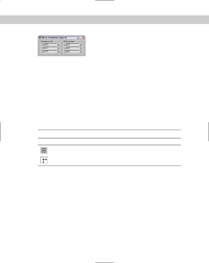
Within the Transform Type-In dialog box are two columns. The first column displays the cur- |
|
rent Absolute coordinates. Updating these coordinates transforms the selected object in the |
|
viewport. The second column displays the Offset values. These values are all set to 0.0 when |
|
the dialog box is first opened, but changing these values transforms the object along the des- |
|
ignated axis by the entered value. Figure 10-4 shows the Transform Type-In dialog box for the |
|
Move Transform. |
Note |
The name of this dialog box changes depending on the type of transformation taking place |
|
and the coordinate system. If the Select and Move button is selected along with the world |
|
coordinate system, the Transform Type-In dialog box is labeled Move Transform Type-In and |
|
the column titles indicate the coordinate system. |
Chapter 10 Transforming Objects—Translate, Rotate, and Scale |
275 |
Figure 10-4: The Transform Type-In dialog box displays the current Absolute coordinates and Offset values.
Using the status bar Type-In fields
The status bar includes three fields labeled X, Y, and Z for displaying transformation coordinates. When you move, rotate, or scale an object, the X, Y, and Z offset values appear in these fields. The values depend on the type of transformation taking place. Translation shows the unit distances, rotation displays the angle in degrees, and scaling shows a percentage value of the original size.
When you click the Select Objects button, these fields show the absolute position of the cursor in world coordinates based on the active viewport.
You can also use these fields to enter values, like with the Transform Type-In dialog box. The type of transform depends on which transform button you select. The values that you enter can be either absolute coordinates or offset values, depending on the setting of the Transform Type-In toggle button that appears to the left of the transform fields. This toggle button lets you switch between Absolute and Offset modes, shown in Table 10-2.
|
Table 10-2: Absolute/Offset Buttons |
Button |
Description |
|
Absolute |
|
Offset |
Understanding the various Transform Managers
The Transform Managers are three different types of controls that help you define the system about which objects are transformed. These controls, found on the main toolbar and on the Axis Constraints toolbar, directly affect your transformations. They include the following:
Reference Coordinate System: Defines the coordinate system about which the transformations take place.
Transform Center settings: The Pivot Point Center, the Selection Center, and the Transform Coordinate Center. These settings specify the center about which the transformations take place.
Axis Constraint settings: Allow the transformation to happen using only one axis or plane. These buttons are on the Axis Constraints toolbar.

276 Part II Working with Objects
Understanding coordinate systems
Max supports several different coordinate systems, and knowing which coordinate system you are working with as you transform an object is important. Using the wrong coordinate system can produce unexpected transformations.
To understand the concept of coordinate systems, imagine that you’re visiting the Grand Canyon and are standing precariously on the edge of a lookout. To nervous onlookers calling the park rangers, the description of your position varies from viewpoint to viewpoint. A person standing by you would say you are next to him. A person on the other side of the canyon would say that you’re across from her. A person at the floor of the canyon would say you’re above him. And a person in an airplane would describe you as being on the east side of the canyon. Each person has a different viewpoint of you (the object), even though you have not moved.
The coordinate systems that Max recognizes include the following:
View Coordinate System: A coordinate system based on the viewports; X points right, Y points up, and Z points out of the screen (toward you). The views are fixed, making this perhaps the most intuitive coordinate system to work with.
Screen Coordinate System: Identical to the View Coordinate System, except the active viewport determines the coordinate system axes, whereas the inactive viewports show the axes as defined by the active viewport.
World Coordinate System: Specifies X pointing to the right, Z pointing up, and Y pointing into the screen (away from you). The coordinate axes remain fixed regardless of any transformations applied to an object.
Parent Coordinate System: Uses the coordinate system applied to a linked object’s parent and maintains consistency between hierarchical transformations. If an object doesn’t have a parent, then the world is its parent and the system works the same as the World Coordinate System.
Local Coordinate System: Sets the coordinate system based on the selected object. The axes are located at the pivot point for the object. You can reorient and move the pivot point using the Pivot button in the Hierarchy panel.
Gimbal Coordinate System: Provides interactive feedback for objects using the Euler XYZ controller. If the object doesn’t use the Euler XYZ controller, then this coordinate system works just like the World coordinate system.
Grid Coordinate System: Uses the coordinate system for the active grid.
Pick Coordinate System: Lets you select an object about which to transform. The Coordinate System list keeps the last four picked objects as coordinate system options.
All transforms occur relative to the current coordinate system as selected in the Referenced Coordinate System drop-down list found on the main toolbar.
Each of the three basic transforms can have a different coordinate system specified, or you can set it to change uniformly when a new coordinate system is selected. To do this, open the General panel in the Preference Settings dialog box, and select the Constant option in the Reference Coordinate System section.
Chapter 10 Transforming Objects—Translate, Rotate, and Scale |
277 |
Using a transform center
All transforms are done about a center point. When transforming an object, you must understand what the object’s current center point is, as well as the coordinate system in which you’re working.
The Transform Center flyout consists of three buttons: Use Pivot Point Center, Use Selection Center, and Use Transform Coordinate Center, shown in Table 10-3. Each of these buttons alters how the transformations are done. The origin of the Transform Gizmo is always positioned at the center point specified by these buttons.
|
Table 10-3: Transform Center Buttons |
|
|
Button |
Description |
|
|
|
Use Pivot Point Center |
|
Use Selection Center |
|
Use Transform Coordinate Center |
|
|
Pivot Point Center
Pivot points are typically set to the center of an object when the object is first created, but they can be relocated anywhere within the scene including outside of the object. Relocating the pivot point allows you to change the point about which objects are rotated. For example, if you have a car model that you want to position along an incline, moving the pivot point to the bottom of one of the tires allows you to easily line up the car with the incline.
Cross- |
Pivot points are discussed in detail in the next section. |
Reference |
|
Selection Center
The Use Selection Center button sets the transform center to the center of the selected object or objects regardless of the individual object’s pivot point. If multiple objects are selected, then the center is computed to be in the middle of a bounding box that surrounds all the objects.
Transform Coordinate Center
The Transform Coordinate Center button uses the center of the Local Coordinate System. If View Coordinate System is selected, then all objects are transformed about the center of the viewport. If an object is selected as the coordinate system using the Pick option, then all transformations are transformed about that object’s center.
278 Part II Working with Objects
When you select the Local Coordinate System, the Use Transform Center button is ignored, and objects are transformed about their local axes. If you select multiple objects, then they all transform individually about their local axes. Grouped objects transform about the group axes.
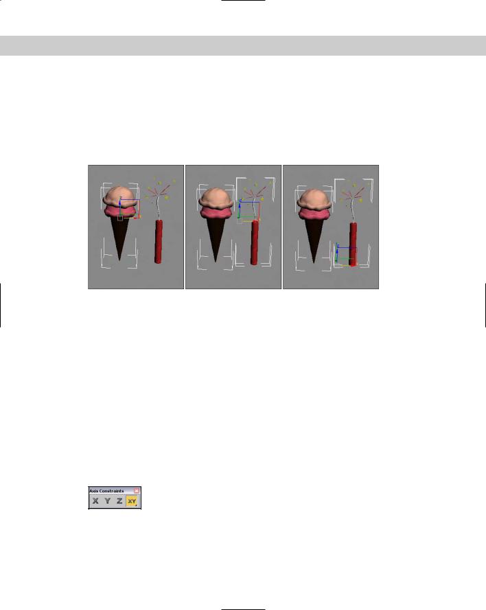
Figure 10-5 shows the ice cream cone and firecracker object using the different transform center modes. The left image shows the Pivot Point Center mode, the middle image shows the Selection Center mode with both objects selected, and the right image shows the Transform Coordinate Center mode. For each mode, notice that the Move Gizmo is in a different location.
Figure 10-5: The Move Gizmo is located in different places depending on the selected Transform Center mode.
Selecting Axis Constraints
Three-dimensional space consists of three basic directions defined by three axes: X, Y, and Z. If you were to stand on each axis and look at a scene, you would see three separate planes: the XY plane, the YZ plane, and the ZX plane. These planes show only two dimensions at a time and restrict any transformations to the two axes. These planes are visible from the Top, Left, and Front viewports.
By default, the Top, Left, and Front viewports show only a single plane and thereby restrict transformations to that single plane. The Top view constrains movement to the XY plane, the Left or Right side view constrains movement to the YZ plane, and the Front view constrains movement to the ZX plane. This setting is adequate for most modeling purposes, but sometimes you might need to limit the transformations in all the viewports to a single plane. In Max, you can restrict movement to specific transform axes using the Restrict Axes buttons in the Axis Constraints toolbar. You access this toolbar, shown in Figure 10-6, by right-clicking on the main toolbar (away from the buttons) and selecting Axis Constraints options from the pop-up menu.
Figure 10-6: The Axis Constraints toolbar includes buttons for restricting transformations to a single axis or plane.
The four Restrict axes buttons are Restrict to X (F5), Restrict to Y (F6), Restrict to Z (F7), and the flyout buttons, Restrict to XY, YZ, and ZX Plane (F8). The effect of selecting one of the Restrict axes buttons is based on the selected coordinate system. For example, if you click the
Chapter 10 Transforming Objects—Translate, Rotate, and Scale |
279 |
Restrict to X button and the coordinate system is set to View, then the object always transforms to the right because, in the View coordinate system, the X-axis is always to the right. If you click the Restrict to X button and the coordinate system is set to Local, the axes are
attached to the object, so transformations along the X-axis is consistent in all viewports (with this setting, the object does not move in the Left view because it shows only the YZ plane).
Caution |
If the axis constraints don’t seem to be working, check the Preference Settings dialog box |
|
and look at the General panel to make sure that the Reference Coordinate System option is |
|
set to Constant. |
Additionally, you can restrict movement to a single plane with the Restrict to Plane flyouts consisting of Restrict to XY, Restrict to YZ, and Restrict to ZX. (Use the F8 key to cycle quickly through the various planes.)
Note If the Transform Gizmo is enabled, then the axis or plane that is selected in the Axis Constraints toolbar initially is displayed in yellow. If you transform an object using a Transform Gizmo, then the respective Axis Constraints toolbar button is selected after you complete the transform.
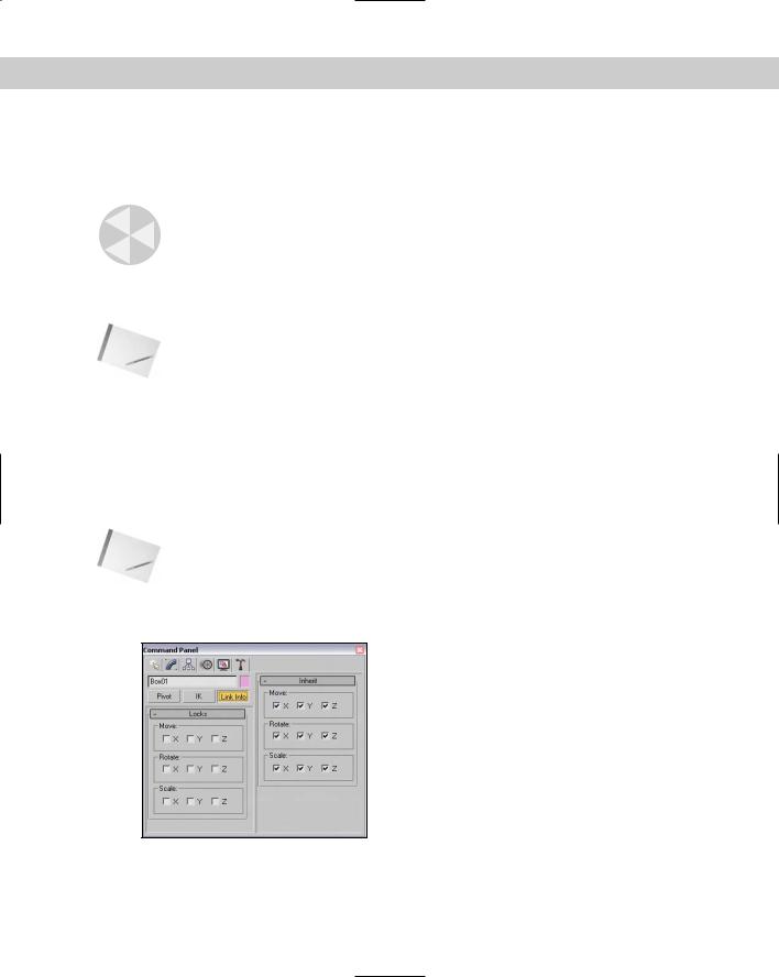
Locking axes and inheriting transformations
To lock an object’s transformation axes on a more permanent basis, go to the Command Panel and select the Hierarchy tab. Click the Link Info button to open the Locks rollout, shown in Figure 10-7. The rollout displays each axis for the three types of transformations: Move, Rotate, and Scale. Make sure that the object is selected, and then click the transformation axes that you want to lock. Be aware that if all Move axes are selected, you won’t be able to move the object until you deselect the axes.
Note |
Another option is to use the Display floater to freeze the object. |
Locking axes is helpful if you want to prevent accidental scaling of an object or restrict a vehicle’s movement to a plane that makes up a road.
Figure 10-7: The Locks and Inherit rollouts can prevent any transforms along an axis and specify which transformations are inherited.
280 Part II Working with Objects
The Locks rollout displays unselected X, Y, and Z check boxes for the Move, Rotate, and Scale transformations. By selecting the check boxes, you limit the axes about which the object can be transformed. For example, if you check the X and Y boxes under the Move transformation, the object can move only in the Z direction of the Local Coordinate System.
Note |
These locks work regardless of the axis constraint settings. |
The Inherit rollout, like the Locks rollout, includes check boxes for each axis and each transformation, except here, all the transformations are selected by default. By deselecting a check box, you specify which transformations an object does not inherit from its parent. The Inherit rollout appears only if the selected object is part of a hierarchy.
For example, suppose that a child object is created and linked to a parent and the X Move Inherit check box is deselected. As the parent is moved in the Y or Z directions, the child follows, but if the parent is moved in the X direction, the child does not follow. If a parent doesn’t inherit a transformation, then its children don’t either.
Using the Link Inheritance utility
The Link Inheritance utility works in the same way as the Inherit rollout of the Hierarchy panel, except that you can apply it to multiple objects at the same time. To use this utility, open the Utility panel and click the More button. In the Utilities dialog box, select the Link Inheritance utility and click OK. The rollout for this utility is identical to the Inherit rollout discussed in the previous section.
Tutorial: Landing a spaceship in port
Transformations are the most basic object manipulation that you will do and probably the most common. This tutorial includes a spaceship object and a spaceport. The goal is to position the spaceship on the landing pad of the spaceport, but it currently is too big and in the wrong spot. With a few clever transformations, we’ll be set.
To transform a spaceship to land in a spaceport, follow these steps:
1.Open the Transforming spaceship.max file from the Chap 10 directory on the CD-ROM.
2.Because we know that the spaceport won’t be moving, we can lock it so it won’t be accidentally moved. To prevent any extraneous movements of the spaceport, select the spaceport by clicking it. Open the Hierarchy panel, and click the Link Info button. Then in the Locks rollout, select all nine boxes to restrict all transformations.
3.The first move for the spaceship is to position it over the landing platform. Select the spaceship object, and click on the Select and Move button in the main toolbar (or press the W key). The Move Gizmo appears in the center of the spaceship object. If you don’t see the Move Gizmo, press the X key. Make sure that the Reference Coordinate System is set to View and that the Use Selection Center option is enabled. Right-click on the Left viewport to make it active, select the red X-axis line of the gizmo, and drag to the right until the center of the spaceship is over the landing pad.
Chapter 10 Transforming Objects—Translate, Rotate, and Scale |
281 |
4.The next move is in the Front viewport to line up the spaceship with the center of the landing pad. Right-click on the Front viewport, and drag the red X-axis gizmo line to the left to line up the spaceship.
5.The next step is to scale down the spaceship to fit on the landing pad. Click the Select and Uniform Scale button (or press the E key). Place the cursor over the center gizmo triangle, and drag downward until the spaceship fits within the landing pad.
6.Click the Select and Move button again (or press the W key), and drag the green Y-axis gizmo line downward in the Front viewport to move the spaceship toward the landing pad.
7.The final transformation is to rotate the spaceship so its front end points away from the buildings. Click the Select and Rotate button (or press the E key). Right-click on the Top viewport, and drag the blue Z-axis gizmo circle downward to rotate the spaceship clockwise.
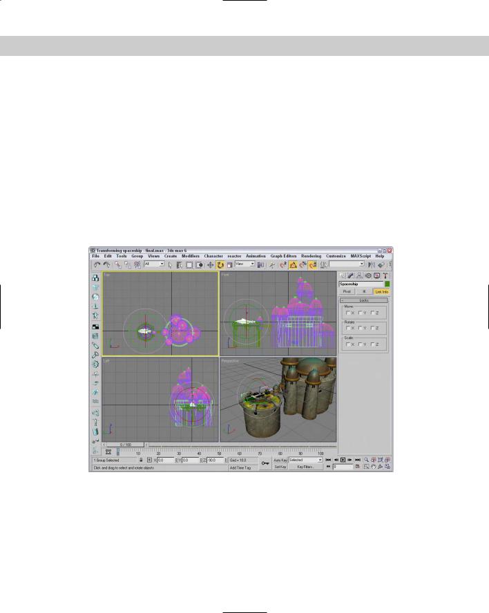
Figure 10-8 shows the spaceship correctly positioned.
Figure 10-8: Transformation buttons and the Transform Gizmos were used to position this spaceship.