


226 Part II Working with Objects
Creating Arrays of Objects
Now that you’ve probably figured out how to create arrays of objects by hand with the Shiftclone method, the Array command multiplies the fun by making it easy to create many copies instantaneously. The Array dialog box lets you specify the array dimensions, offsets, and transformation values. These parameters enable you to create an array of objects easily.
Access the Array dialog box by selecting an object and choosing Tools Array or by clicking the Array button on the Extras toolbar. Figure 7-11 shows the Array dialog box.
The top of the Array dialog box displays the coordinate system and the center about which the transformations are performed.
The Array dialog box is persistent, meaning that, after being applied, the settings remain until they are changed. You can reset all the values at once by clicking the Reset All Parameters button.
Figure 7-11: The Array dialog box defines the number of elements and transformation offsets in an array.
Linear arrays
Linear arrays are arrays where the objects form straight lines, such as rows and columns. Using the Array dialog box, you can specify an offset along the X, Y, and Z axes at the top of the dialog box and define this offset as an incremental amount or as a total amount. To change between incremental values and total values, click the arrows to the left and right of the Move, Rotate, and Scale labels. For example, an array with ten elements and an incremental value of 5 positions each successive object a distance of five units from the previous one. An array with five elements and a total value of 100 positions each element a distance of 20 units from the previous one.
The Move row values represent units as specified in the Units Setup dialog box. The Rotate row values represent degrees, and the Scale row values are a percentage of the selected object. All values can be either positive or negative values.
Clicking the Re-Orient check box causes the coordinate system to be reoriented after each rotation is made. If this check box isn’t enabled, then the objects in the array do not successively rotate. Clicking the Uniform check box to the right of the Scale row values disables the Y and Z Scale value columns and forces the scaling transformations to be uniform. To perform non-uniform scaling, simply deselect the Uniform check box.

Chapter 7 Cloning Objects and Creating Object Arrays |
227 |
The Type of Object section lets you define whether the new objects are copies, instances, or references. If you plan on modeling all the objects in a similar manner, then you will want to select the Instance or Reference options.
In the Array Dimensions section, you can specify the number of objects to copy along three different dimensions. You can also define incremental offsets for each individual row.
Caution |
You can use the Array dialog box to create a large number of objects. If your array of objects |
|
is too large, your system may crash. |
Tutorial: Building a white picket fence
To start with a simple example, we create a white picket fence. Because a fence repeats, we need only to create a single slat and then we use the Array command to duplicate it consistently.
To create a picket fence, follow these steps:
1.Open the White picket fence.max file from the Chap 07 directory on the CD-ROM.
2.With the single fence board selected, choose Tools Array or click on the Array button on the Extras toolbar to open the Array dialog box.
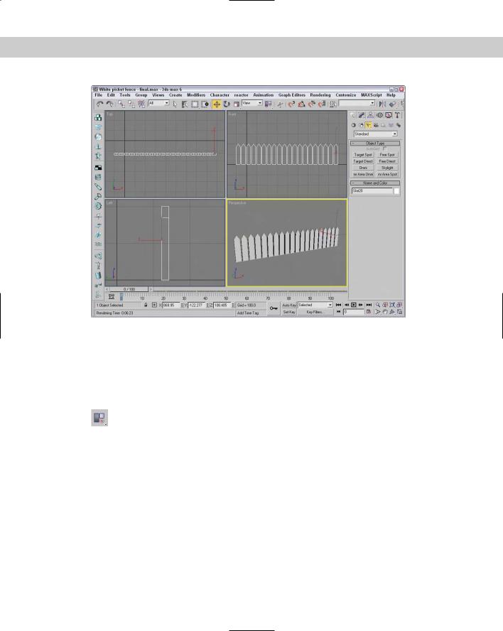
3.In the Array dialog box, click the Reset All Parameters button to start with a clean slate. Then enter a value of 50 in the X column’s Move row under the Incremental section. (This is the incremental value for spacing each successive picket.) Next, enter 20 in the Array Dimensions section next to the 1D radio button. (This is the number of objects to include in the array.) Click OK to create the objects.
Note Don’t worry if you don’t get the values right the first time. The most recent values you entered into the Array dialog box stay around until you exit Max.
4.Click the Zoom Extents All button (or press Shift+Ctrl+Z) in the lower-right corner of the Max window to see the entire fence in the viewports.
Figure 7-12 shows the completed fence.
Circular arrays
You can use the Array dialog box for creating more than just linear arrays. All transformations are done relative to a center point. You can change the center point about
which transformations are performed using the Use Selection Center button on the main toolbar. The three flyout options are Use Pivot Point Center, Use Selection Center, and Use Transform Coordinate Center.
Cross- |
For more about how these settings affect transformations, see Chapter 10, “Transforming |
Reference |
Objects — Translate, Rotate, and Scale.” |
|
228 Part II Working with Objects
Figure 7-12: Tom Sawyer would be pleased to see this white picket fence, created easily with the Array dialog box.
Tutorial: Building a Ferris wheel
Ferris wheels, like most of the rides at the fair, entertain by going around and around, with the riders seated in chairs spaced around the Ferris wheel’s central point. The Array dialog box can also create objects around a central point.
In this example, you use the Rotate transformation along with the Use Transform Coordinate Center button to create a circular array.
To create a circular array, follow these steps:
1.Open the Ferris wheel.max file from the Chap 07 directory on the CD-ROM.
This file has the Front viewport maximized to show the profile of the Ferris wheel.
2.Click the Use Selection Center button on the main toolbar, and drag down to the last icon, which is the Use Transform Coordinate Center button.
The Use Transform Coordinate Center button becomes active. This button causes all transformations to take place about the axes in the center of the screen.
3.Select the light blue chair object, and open the Array dialog box by choosing Tools Array or by clicking the Array button on the Extras toolbar. Before entering any values into the Array dialog box, click the Reset All Parameters button.
Chapter 7 Cloning Objects and Creating Object Arrays |
229 |
4.Between the Incremental and Totals sections are the labels Move, Rotate, and Scale. Click the arrow button to the right of the Rotate label. Set the Z column value of the Rotate row to 360 degrees, and make sure that the Re-Orient option is disabled.
A value of 360 degrees defines one complete revolution. Disabling the Re-Orient option keeps each chair object from gradually turning upside down.
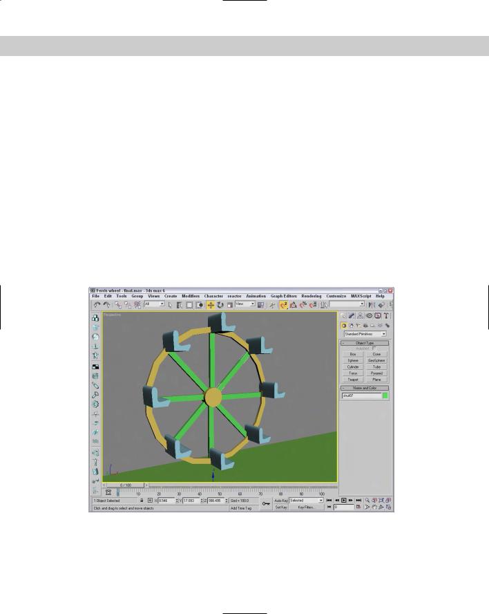
5.In the Array Dimensions section, set the 1D spinner Count value to 8 and click the OK button to create the array.
6.Next select the green strut, and open the Array dialog box again with the Tools Array command. Select the Re-Orient option, and leave the rest of the settings as they are. Click the OK button to create the array.
Figure 7-13 shows the resulting Ferris wheel. You can click the Min/Max toggle in the lowerright corner to view all four viewports again.
Spiral arrays
Before leaving arrays, we should examine one more special case: spiral arrays. A spiral array results from moving and rotating objects along the same axis. Combinations of transforms in the Array dialog box can produce many interesting modeling possibilities.
Figure 7-13: A circular array created by rotating objects about the Transform Coordinate Center
230 Part II Working with Objects
New |
3ds max 6 includes a new primitive object type for creating spiral staircases. Check it out in |
Feature |
the AEC Objects submenu in the Create menu. |
|
Tutorial: Building a spiral staircase
To create a spiral staircase, we will first need to create a simple rectangular box that can be used for the steps. Because a spiral staircase winds about a center pole, we will need our transform’s center to be located at one end of the stair object.
To create a spiral staircase, follow these steps:
1.Open the Spiral staircase.max file from the Chap 07 directory on the CD-ROM.
This file has the Top viewport maximized, which is the easiest view in which to create the spiral staircase.
2.Select the Use Transform Coordinate Center flyout from the Use Center button on the main toolbar.
This setting transforms the selected object about the center of the active viewport. You should notice that the axes are relocated to the center of the viewport.
3.Select the single stair, and open the Array dialog box by choosing Tools Array or by clicking the Array button on the Extras toolbar. Before entering any values into the Array dialog box, click the Reset All Parameters button.
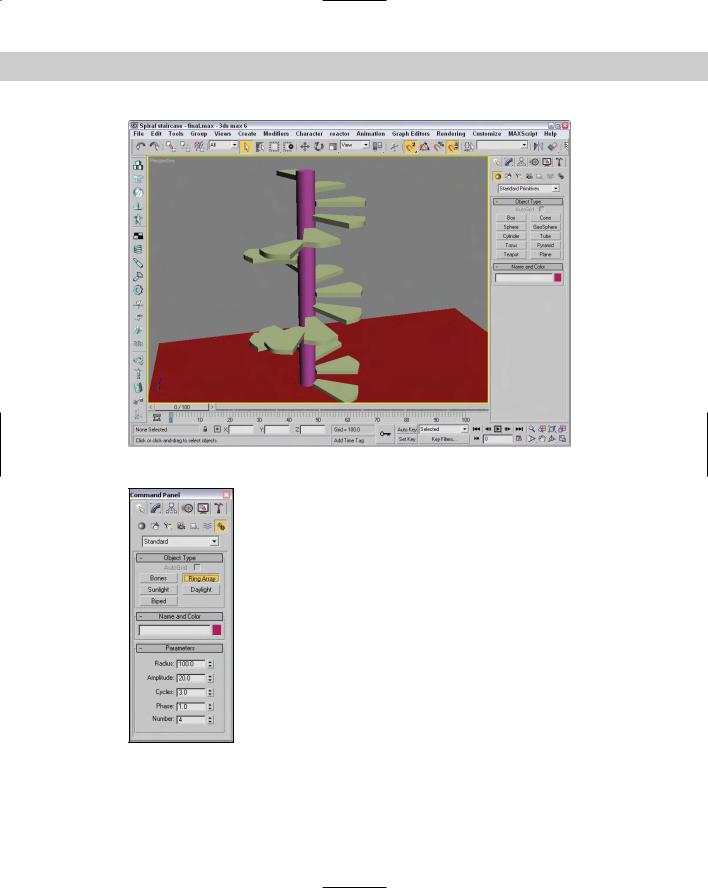
4.In the Incremental section, enter the value of 50 in the Z column of the Move row, and 45 in the Z column of the Rotate row.
5.Set the 1D Count spinner to 20, and click the OK button to create the array.
Figure 7-14 shows the results of the spiral array in the Perspective viewport.
Working with a ring array
You can find the Ring Array system by opening the Create panel and selecting the Systems category. Clicking the Ring Array button opens a Parameters rollout, shown in Figure 7-15. In this rollout are parameters for the ring’s Radius, Amplitude, Cycles, Phase, and the Number of elements to include.
Note The Ring Array command is missing from the Create menu.
You create the actual array by clicking and dragging in one of the viewports. Initially, all elements are simple box objects surrounding a green dummy object.
Chapter 7 Cloning Objects and Creating Object Arrays |
231 |
Figure 7-14: Getting fancy with the Array feature produced this spiral staircase.
Figure 7-15: The Parameters rollout of the Ring Array system can create an oscillating circular array of objects.
232 Part II Working with Objects
Cross- You can change the boxes that appear as part of the ring array to another object using the Reference Track View. To do so, you need to locate the copy object’s track and paste it where the ring
array’s boxes are. Chapter 33, “Working with the Track View,” shows how to do this.
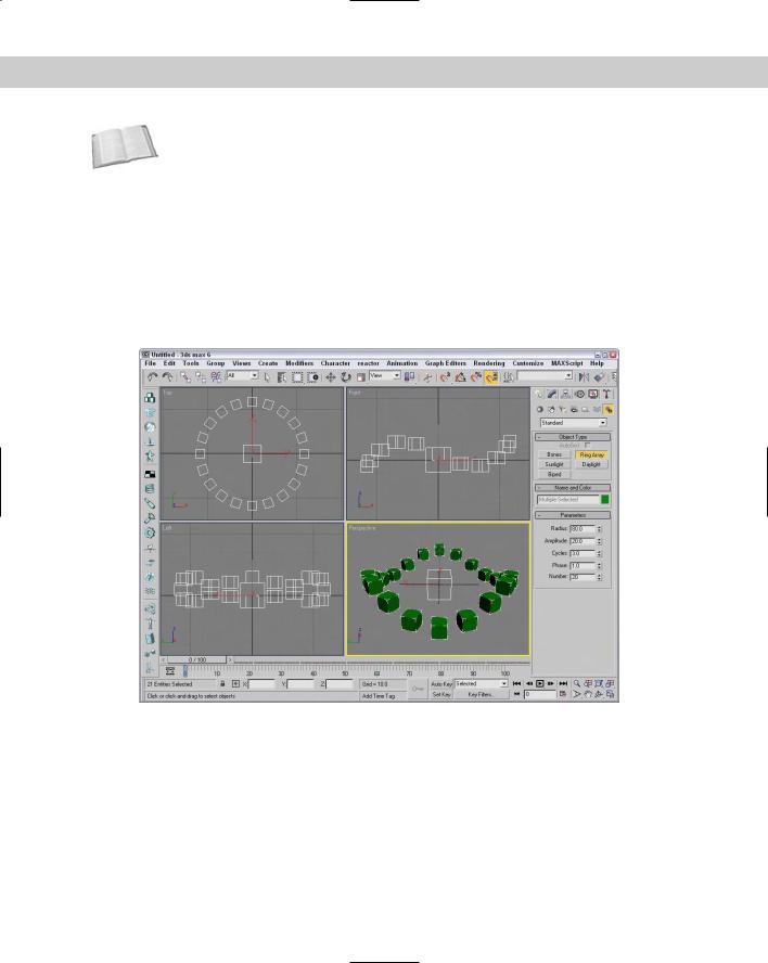
The Amplitude, Cycles, and Phase values define the sinusoidal nature of the circle. The Amplitude is the maximum distance that you can position the objects from the horizontal plane. If the Amplitude is set to 0, then all objects lie in the same horizontal plane. The Cycles value is the number of waves that occur around the entire circle. The Phase determines which position along the circle starts in the up position.
For example, Figure 7-16 shows a ring array with 20 elements, a Radius of 80, an Amplitude of 20, a Cycles value of 3, and a Phase of 1.0. The Dummy object in the middle lets you control the entire ring’s position and orientation. If you want to animate a wave-like motion, you can animate the Phase value moving between 0 and 1.
Figure 7-16: This ring array has only two cycles.
Tutorial: Using Ring Array to create a carousel
Continuing with the theme park attractions motif, this example creates a carousel. The horse model comes from Poser, but was simplified using the MultiRes modifier.
To use a Ring Array system to create a carousel, follow these steps.
1.Open the Carousel.max file from the Chap 07 directory on the CD-ROM.
This file includes a carousel structure made from primitives along with a carousel horse.
Chapter 7 Cloning Objects and Creating Object Arrays |
233 |
2.Open the Create panel, select the Systems category, and click the Ring Array button. Drag in the Top viewport from the center of the carousel to create a ring array. Then enter a Radius value of 250, an Amplitude of 20, a Cycles value of 3, and a Number value of 6.
3.Select the Dummy object in the Left viewport, and drag it upward with the Select and Move tool until all the box objects are positioned between the carousel base and the top cone.
4.Select the horse object, and click on the Mini Curve Editor button to the left of the Track Bar. This opens the Track View to the horse object. Scroll downward in the Track View to the Object (Editable Mesh) track, and select it. Then right-click and select Copy from the pop-up menu.
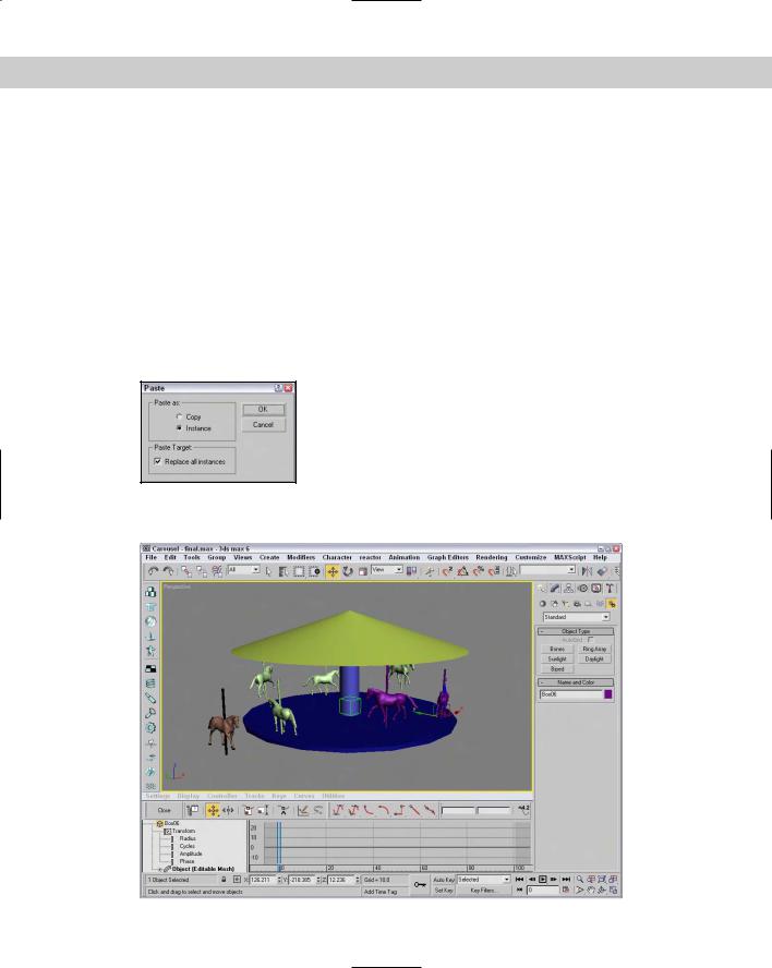
5.Click one of the Ring Array dummy objects, and the Track View locates the Box object that is part of the Ring Array. Then right-click and select the Paste command from the pop-up menu. This opens the Paste dialog, shown in Figure 7-17. Select Instance and the Replace all Instances option, and click OK.
Figure 7-17: This Paste dialog lets you replace all instances.
Figure 7-18 shows the finished carousel. Notice that each horse is at a different height.
Figure 7-18: The horses in the carousel were created using a Ring Array system.