

- •Preface
- •About This Book
- •Acknowledgments
- •Contents at a Glance
- •Contents
- •Relaxing at the Beach
- •Dressing the Scene
- •Animating Motion
- •Rendering the Final Animation
- •Summary
- •The Interface Elements
- •Using the Menus
- •Using the Toolbars
- •Using the Viewports
- •Using the Command Panel
- •Using the Lower Interface Bar Controls
- •Interacting with the Interface
- •Getting Help
- •Summary
- •Understanding 3D Space
- •Using the Viewport Navigation Controls
- •Configuring the Viewports
- •Working with Viewport Backgrounds
- •Summary
- •Working with Max Scene Files
- •Setting File Preferences
- •Importing and Exporting
- •Referencing External Objects
- •Using the File Utilities
- •Accessing File Information
- •Summary
- •Customizing Modify and Utility Panel Buttons
- •Working with Custom Interfaces
- •Configuring Paths
- •Selecting System Units
- •Setting Preferences
- •Summary
- •Creating Primitive Objects
- •Exploring the Primitive Object Types
- •Summary
- •Selecting Objects
- •Setting Object Properties
- •Hiding and Freezing Objects
- •Using Layers
- •Summary
- •Cloning Objects
- •Understanding Cloning Options
- •Mirroring Objects
- •Cloning over Time
- •Spacing Cloned Objects
- •Creating Arrays of Objects
- •Summary
- •Working with Groups
- •Building Assemblies
- •Building Links between Objects
- •Displaying Links and Hierarchies
- •Working with Linked Objects
- •Summary
- •Using the Schematic View Window
- •Working with Hierarchies
- •Setting Schematic View Preferences
- •Using List Views
- •Summary
- •Working with the Transformation Tools
- •Using Pivot Points
- •Using the Align Commands
- •Using Grids
- •Using Snap Options
- •Summary
- •Exploring the Modifier Stack
- •Exploring Modifier Types
- •Summary
- •Exploring the Modeling Types
- •Working with Subobjects
- •Modeling Helpers
- •Summary
- •Drawing in 2D
- •Editing Splines
- •Using Spline Modifiers
- •Summary
- •Creating Editable Mesh and Poly Objects
- •Editing Mesh Objects
- •Editing Poly Objects
- •Using Mesh Editing Modifiers
- •Summary
- •Introducing Patch Grids
- •Editing Patches
- •Using Modifiers on Patch Objects
- •Summary
- •Creating NURBS Curves and Surfaces
- •Editing NURBS
- •Working with NURBS
- •Summary
- •Morphing Objects
- •Creating Conform Objects
- •Creating a ShapeMerge Object
- •Creating a Terrain Object
- •Using the Mesher Object
- •Working with BlobMesh Objects
- •Creating a Scatter Object
- •Creating Connect Objects
- •Modeling with Boolean Objects
- •Creating a Loft Object
- •Summary
- •Understanding the Various Particle Systems
- •Creating a Particle System
- •Using the Spray and Snow Particle Systems
- •Using the Super Spray Particle System
- •Using the Blizzard Particle System
- •Using the PArray Particle System
- •Using the PCloud Particle System
- •Using Particle System Maps
- •Controlling Particles with Particle Flow
- •Summary
- •Understanding Material Properties
- •Working with the Material Editor
- •Using the Material/Map Browser
- •Using the Material/Map Navigator
- •Summary
- •Using the Standard Material
- •Using Shading Types
- •Accessing Other Parameters
- •Using External Tools
- •Summary
- •Using Compound Materials
- •Using Raytrace Materials
- •Using the Matte/Shadow Material
- •Using the DirectX 9 Shader
- •Applying Multiple Materials
- •Material Modifiers
- •Summary
- •Understanding Maps
- •Understanding Material Map Types
- •Using the Maps Rollout
- •Using the Map Path Utility
- •Using Map Instances
- •Summary
- •Mapping Modifiers
- •Using the Unwrap UVW modifier
- •Summary
- •Working with Cameras
- •Setting Camera Parameters
- •Summary
- •Using the Camera Tracker Utility
- •Summary
- •Using Multi-Pass Cameras
- •Creating Multi-Pass Camera Effects
- •Summary
- •Understanding the Basics of Lighting
- •Getting to Know the Light Types
- •Creating and Positioning Light Objects
- •Viewing a Scene from a Light
- •Altering Light Parameters
- •Working with Photometric Lights
- •Using the Sunlight and Daylight Systems
- •Using Volume Lights
- •Summary
- •Selecting Advanced Lighting
- •Using Local Advanced Lighting Settings
- •Tutorial: Excluding objects from light tracing
- •Summary
- •Understanding Radiosity
- •Using Local and Global Advanced Lighting Settings
- •Working with Advanced Lighting Materials
- •Using Lighting Analysis
- •Summary
- •Using the Time Controls
- •Working with Keys
- •Using the Track Bar
- •Viewing and Editing Key Values
- •Using the Motion Panel
- •Using Ghosting
- •Animating Objects
- •Working with Previews
- •Wiring Parameters
- •Animation Modifiers
- •Summary
- •Understanding Controller Types
- •Assigning Controllers
- •Setting Default Controllers
- •Examining the Various Controllers
- •Summary
- •Working with Expressions in Spinners
- •Understanding the Expression Controller Interface
- •Understanding Expression Elements
- •Using Expression Controllers
- •Summary
- •Learning the Track View Interface
- •Working with Keys
- •Editing Time
- •Editing Curves
- •Filtering Tracks
- •Working with Controllers
- •Synchronizing to a Sound Track
- •Summary
- •Understanding Your Character
- •Building Bodies
- •Summary
- •Building a Bones System
- •Using the Bone Tools
- •Using the Skin Modifier
- •Summary
- •Creating Characters
- •Working with Characters
- •Using Character Animation Techniques
- •Summary
- •Forward versus Inverse Kinematics
- •Creating an Inverse Kinematics System
- •Using the Various Inverse Kinematics Methods
- •Summary
- •Creating and Binding Space Warps
- •Understanding Space Warp Types
- •Combining Particle Systems with Space Warps
- •Summary
- •Understanding Dynamics
- •Using Dynamic Objects
- •Defining Dynamic Material Properties
- •Using Dynamic Space Warps
- •Using the Dynamics Utility
- •Using the Flex Modifier
- •Summary
- •Using reactor
- •Using reactor Collections
- •Creating reactor Objects
- •Calculating and Previewing a Simulation
- •Constraining Objects
- •reactor Troubleshooting
- •Summary
- •Understanding the Max Renderers
- •Previewing with ActiveShade
- •Render Parameters
- •Rendering Preferences
- •Creating VUE Files
- •Using the Rendered Frame Window
- •Using the RAM Player
- •Reviewing the Render Types
- •Using Command-Line Rendering
- •Creating Panoramic Images
- •Getting Printer Help
- •Creating an Environment
- •Summary
- •Creating Atmospheric Effects
- •Using the Fire Effect
- •Using the Fog Effect
- •Summary
- •Using Render Elements
- •Adding Render Effects
- •Creating Lens Effects
- •Using Other Render Effects
- •Summary
- •Using Raytrace Materials
- •Using a Raytrace Map
- •Enabling mental ray
- •Summary
- •Understanding Network Rendering
- •Network Requirements
- •Setting up a Network Rendering System
- •Starting the Network Rendering System
- •Configuring the Network Manager and Servers
- •Logging Errors
- •Using the Monitor
- •Setting up Batch Rendering
- •Summary
- •Compositing with Photoshop
- •Video Editing with Premiere
- •Video Compositing with After Effects
- •Introducing Combustion
- •Using Other Compositing Solutions
- •Summary
- •Completing Post-Production with the Video Post Interface
- •Working with Sequences
- •Adding and Editing Events
- •Working with Ranges
- •Working with Lens Effects Filters
- •Summary
- •What Is MAXScript?
- •MAXScript Tools
- •Setting MAXScript Preferences
- •Types of Scripts
- •Writing Your Own MAXScripts
- •Learning the Visual MAXScript Editor Interface
- •Laying Out a Rollout
- •Summary
- •Working with Plug-Ins
- •Locating Plug-Ins
- •Summary
- •Low-Res Modeling
- •Using Channels
- •Using Vertex Colors
- •Rendering to a Texture
- •Summary
- •Max and Architecture
- •Using AEC Objects
- •Using Architectural materials
- •Summary
- •Tutorial: Creating Icy Geometry with BlobMesh
- •Tutorial: Using Caustic Photons to Create a Disco Ball
- •Summary
- •mental ray Rendering System
- •Particle Flow
- •reactor 2.0
- •Schematic View
- •BlobMesh
- •Spline and Patch Features
- •Import and Export
- •Shell Modifier
- •Vertex Paint and Channel Info
- •Architectural Primitives and Materials
- •Minor Improvements
- •Choosing an Operating System
- •Hardware Requirements
- •Installing 3ds max 6
- •Authorizing the Software
- •Setting the Display Driver
- •Updating Max
- •Moving Max to Another Computer
- •Using Keyboard Shortcuts
- •Using the Hotkey Map
- •Main Interface Shortcuts
- •Dialog Box Shortcuts
- •Miscellaneous Shortcuts
- •System Requirements
- •Using the CDs with Windows
- •What’s on the CDs
- •Troubleshooting
- •Index
916 Part IX Dynamics
Binding a Space Warp to an object
A Space Warp’s influence is felt only by its bound objects, so you can selectively apply gravity to only certain objects. The Bind to Space Warp button is on the main toolbar
next to the Unlink button. After clicking the Bind to Space Warp button, drag from the Space Warp to the object to which you want to link it or vice versa.
All Space Warp bindings appear in the Modifier Stack. You can use the Edit Modifier Stack dialog box to copy and paste Space Warps between objects.
Note If you look at the Modifier Stack for an object that is bound to a Space Warp, you’ll see an asterisk in front of the name. This asterisk denotes that the Space Warp is applied using World coordinates.
Some Space Warps can be bound only to certain types of objects. Each Space Warp has a Supports Objects of Type rollout that lists the supported objects. If you’re having trouble binding a Space Warp to an object, check this rollout to see whether the object is supported.
Understanding Space Warp Types
Just as many different types of forces exist in nature, many different Space Warp types exist. These appear in four different subcategories, based on their function. The four subcategories are Forces, Deflectors, Geometric/Deformable, and Modifier-Based.
Cross- |
Although it is available in the Create Space Warps menu, the Create panel includes a reac- |
Reference |
tor category that makes the Water button available. The Water reactor object is discussed |
|
|
|
with the rest of the reactor objects in Chapter 40, “Animating with reactor.” |
Force Space Warps
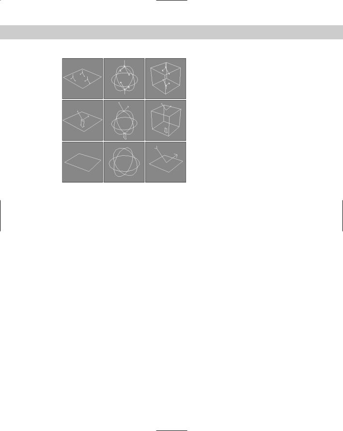
The Forces subcategory of Space Warps is mainly used with particle systems and dynamic simulations. Space Warps in this subcategory include Motor, Vortex, Path Follow, Displace, Wind, Push, Drag, PBomb, and Gravity. Figure 38-1 shows the gizmos for these Space Warps.
Figure 38-1: The Force Space Warps: Motor, Vortex, Path Follow, Displace, Wind, Push, Drag, PBomb, and Gravity
Chapter 38 Using Space Warps 917
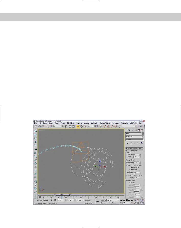
Motor
The Motor Space Warp applies a rotational torque to objects. This force accelerates objects radially instead of linearly. The Basic Torque value is a measurement of torque in newtonmeters, foot-pounds, or inch-pounds.
The On Time and Off Time options set the frames where the force is applied and disabled, respectively. Many of the Space Warps have these same values.
The Feedback On option causes the force to change as the object’s speed changes. When this option is off, the force stays constant. You can also set a Target Revolution units in revolutions per hour (RPH), revolutions per minute (RPM), or revolutions per second (RPS), which is the speed at which the force begins to change if the Feedback option is enabled. The Reversible option causes the force to change directions if the Target Speed is reached, and the Gain value is how quickly the force adjusts.
The motor force can also be adjusted with Periodic Variations, which cause the motor force to increase and then decrease in a regular pattern. You can define two different sets of Periodic Variation parameters: Period 1, Amplitude 1, Phase 1; and Period 2, Amplitude 2, Phase 2.
For particle systems, you can enable and set a Range value. The Motor Space Warp doesn’t affect particles outside this distance. At the bottom of the Parameters rollout, you can set the size of the gizmo icon. You can find this same value for all Space Warps.
Figure 38-2 shows the Motor Space Warp twisting the particles being emitted from the Super Spray particle system in the direction of the icon’s arrow.
Figure 38-2: You can use the Motor Space Warp to apply a twisting force to particles and dynamic objects.
918 Part IX Dynamics
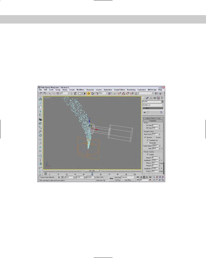
Push
The Push Space Warp accelerates objects in the direction of the Space Warp’s icon from the large cylinder to the small cylinder. Many of the parameters for the Push Space Warp are similar to those for the Motor Space Warp. Using the Parameters rollout, you can specify the force Strength in units of newtons or pounds.
The Feedback On option causes the force to change as the object’s speed changes, except that it deals with Target Speed instead of Target Revolution like the Motor Space Warp does.
The push force can also be set to include Periodic Variations that are the same as with the Motor Space Warp. Figure 38-3 shows the Push Space Warp pushing the particles being emitted from the Super Spray particle system.
Figure 38-3: You can use the Push Space Warp to apply a controlled force to particles and dynamic objects.
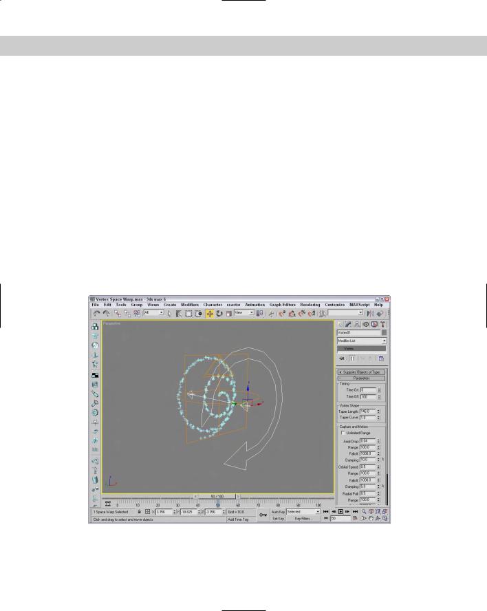
Vortex
You can use the Vortex Space Warp on particle systems to make particles spin around in a spiral like going down a whirlpool. You can use the Timing settings to set the beginning and ending frames where the effect takes place.
You can also specify Taper Length and Curve values, which determine the shape of the vortex. Lower Taper Length values wind the vortex tighter, and the Taper Curve values can range
Chapter 38 Using Space Warps 919
between 1.0 and 4.0 and control the ratio between the spiral diameter at the top of the vortex versus the bottom of the vortex.
The Axial Drop value specifies how far each turn of the spiral is from the adjacent turn. The Damping value sets how quickly the Axial Drop value takes effect. The Orbital Speed is how fast the particles rotate away from the center. The Radial Pull value is the distance from the center of each spiral path that the particles can rotate. If the Unlimited Range option is disabled, then Range and Falloff values are included for each setting. You can also specify whether the vortex spins clockwise or counterclockwise.
Figure 38-4 shows a Vortex Space Warp being bound to a particle system.
Drag
Drag is another common force that can be simulated with a Space Warp. The Drag Space Warp can be Linear, Spherical, or Cylindrical. This Space Warp causes particle velocity to be decreased, such as when simulating wind drag or viscosity. Use the Time On and Time Off options to set the frame where the Space Warp is in effect.
For each of the Damping shape types — Linear, Spherical, and Cylindrical — you can set the drag along each axis or in the Radial, Tangential, or Axial direction, depending on the shape. If the Unlimited Range option is not selected, then the Range and Falloff values are available.
Figure 38-5 shows a Drag Space Warp surrounding a particle system.
Figure 38-4: You can use the Vortex Space Warp to spiral a particle system like a whirlpool.
920 Part IX Dynamics
Figure 38-5: You can use the Drag Space Warp to slow the velocity of particles.
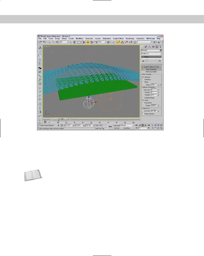
PBomb
The PBomb (particle bomb) Space Warp was designed specifically for the PArray particle system. To blow up an object with the PBomb Space Warp, create an object, make it a PArray emitter, and then bind the PBomb Space Warp to the PArray.
Cross- |
You can find more information on the PArray particle system in Chapter 18, “Creating |
Reference |
Particles and Particle Flow.” |
|
Basic parameters for this Space Warp include three blast symmetry types: Spherical, Cylindrical, and Planar. You can also set the Chaos value as a percentage.
In the Explosion Parameters section, the Start Time is the frame where the explosion takes place, and the Duration defines how long the explosion forces are applied. The Strength value is the power of the explosion.
A Range value can be set to determine the extent of the explosion. It is measured from the center of the Space Warp icon. If the Unlimited Range option is selected, the Range value is disabled. The Linear and Exponential options change how the explosion forces die out. The Range Indicator option displays the effective blast range of the PBomb.
Figure 38-6 shows a box selected as an emitter for a PArray. The PBomb is bound to the PArray and not to the box object. The Speed value for the PArray has been set to 0, and the Particle Type is set to Fragments. Notice that the PBomb’s icon determines the center of the blast.
Chapter 38 Using Space Warps 921
Figure 38-6: You can use the PBomb Space Warp with the PArray particle system to create explosions.
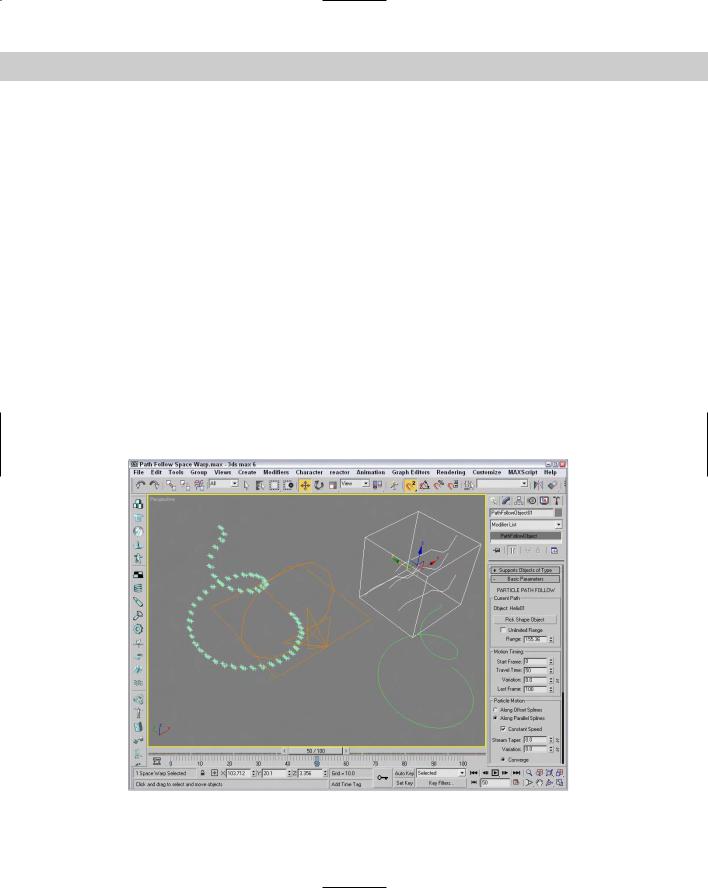
Path Follow
The Path Follow Space Warp causes particles to follow a path defined by a spline. The Basic Parameters rollout for this Space Warp includes a Pick Shape Object button for selecting the spline path to use. You can also specify a Range value or the Unlimited Range option. The Range distance is measured from the path to the particle.
Cross- |
The Path Follow Space Warp is similar to the Path Constraint, which is discussed in Chapter |
Reference |
31, “Animating with Constraints and Controllers.” |
|
In the Motion Timing section, the Start Frame value is the frame where the particles start following the path, the Travel Time is the number of frames required to travel the entire path, and the Last Frame is where the particles no longer follow the path. There is also a Variation value to add some randomness to the movement of the particles.
The Basic Parameters rollout also includes a Particle Motion section with two options for controlling how the particles proceed down the path: Along Offset Splines and Along Parallel Splines. The first causes the particles to move along splines that are offset from the original, and the second moves all particles from their initial location along parallel path splines. The Constant Speed option makes all particles move at the same speed.
Also in the Particle Motion section is the Stream Taper value. This value is the amount by which the particles move away from the path over time. Options include Converge, Diverge,
922 Part IX Dynamics
or Both. Converging streams move all particles closer to the path, and diverging streams do the opposite. The Stream Swirl value is the number of spiral turns that the particles take along the path. This swirling motion can be Clockwise, Counterclockwise, or Bidirectional. The Seed value determines the randomness of the stream settings.
Figure 38-7 shows a Path Follow Space Warp bound to a Super Spray particle system. A Helix shape has been selected as the path.
Gravity
The Gravity Space Warp adds the effect of gravity to a scene. This causes objects to accelerate in the direction specified by the Gravity Space Warp, like the Wind Space Warp. The Parameters rollout includes Strength and Decay values. There are also options to make the gravity planar or spherical. You can turn on the Range Indicators to display a plane or sphere where the gravity is half its maximum value.
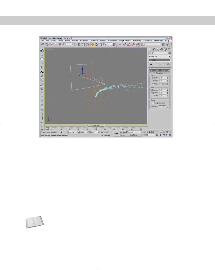
Wind
The Wind Space Warp causes objects to accelerate. The Parameters rollout includes Strength and Decay values. There are also options to make the gravity planar or spherical. The Turbulence value randomly moves the objects in different directions, and the Frequency value controls how often these random turbulent changes occur. Larger Scale values cause turbulence to affect larger areas, but smaller values are more wild and chaotic.
You can turn on the Range Indicators just like the Gravity Space Warp. Figure 38-8 shows the Wind Space Warp pushing the particles being emitted from a Super Spray particle system.
Figure 38-7: A Path Follow Space Warp bound to an emitter from the Super Spray particle system and following a Helix path
Chapter 38 Using Space Warps 923
Figure 38-8: You can use the Wind Space Warp to blow particles and dynamic objects.
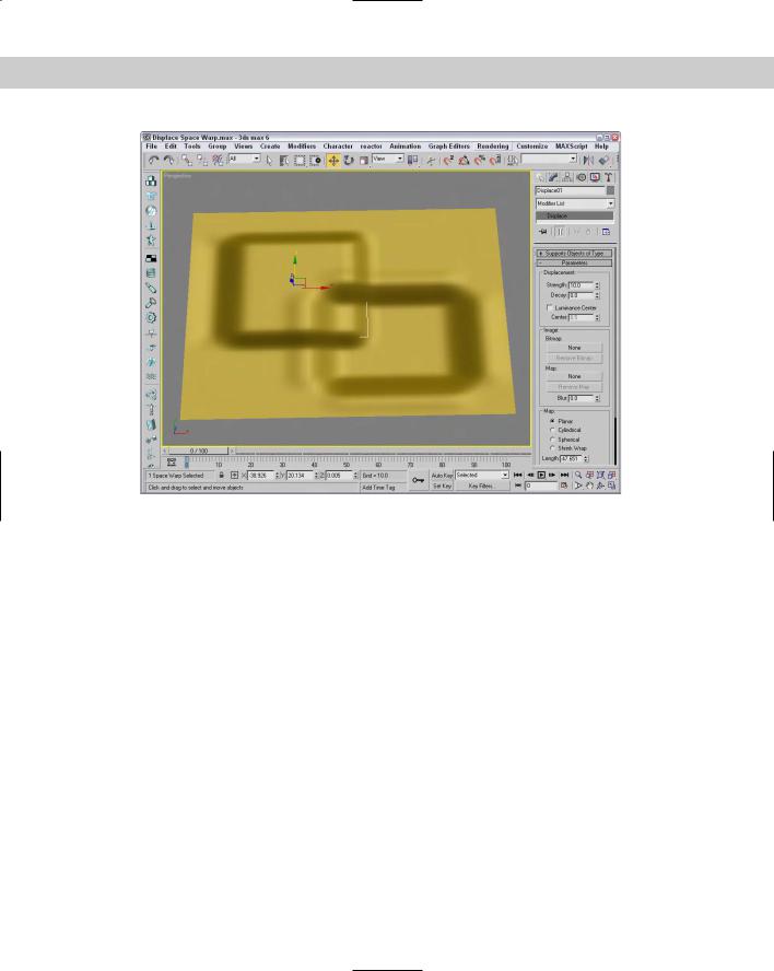
Displace
The Displace Space Warp is like a force field: It pushes objects and is useful when applied to a particle system. It can also work on any deformable object in addition to particle systems. The strength of the displacement can be defined with Strength and Decay values or with a grayscale bitmap.
The Strength value is the distance that the geometry is displaced and can be positive or negative. The Decay value causes the displacement to decrease as the distance increases. The Luminance Center is the grayscale point where no displacement occurs; any color darker than this center value is moved away, and any brighter areas move closer.
The Bitmap and Map buttons let you load images to use as a displacement map; the amount of displacement corresponds with the brightness of the image. There is also a Blur setting for blurring the image. You can apply these maps with different mapping options, including Planar, Cylindrical, Spherical, and Shrink Wrap. You can also adjust the Length, Width, and Height dimensions and the U, V, and W Tile values.
Cross- |
The Displace Space Warp is similar in function to the Displace modifier. The Displace modifier |
Reference |
is discussed in Chapter 22, “Adding Material Details with Maps.” |
|
Figure 38-9 shows two Displace Space Warps with opposite Strength values.
924 Part IX Dynamics
Figure 38-9: The Displace Space Warp can raise or indent the surface of a patch grid.
Deflector Space Warps
The Deflectors subcategory of Space Warps includes PDynaFlect, SDynaFlect, UDynaFlect, POmniFlect, SOmniFlect, UOmniFlect, Deflector, SDeflector, and UDeflector. You use them all with particle systems, but only the DynaFlect Space Warps can be used with dynamic objects. This category includes several different types of deflectors starting with P, S, and U. The difference between these types is their shape. P-type (planar) deflectors are box shaped, S-type (spherical) deflectors are spherical, and U-type (universal) deflectors include a Pick Object button that you can use to select any object as a deflector.
Figure 38-10 shows the icons for each of these Space Warps. All the P-type deflectors are in the first row, the S-type deflectors are in the second row, and the U-type deflectors are in the third row.
PDynaFlect, SDynaFlect, and UDynaFlect
The PDynaFlect Space Warp enables particles to affect other objects in a scene. It is planar in shape. The SDynaFlect Space Warp is similar to the PDynaFlect Space Warp, except that its shape is spherical. The shape of the UDynaFlect Space Warp can be any other object within the scene. All three of these Space Warps share roughly the same parameters.
Chapter 38 Using Space Warps 925
Figure 38-10: The Deflector Space Warps:
POmniFlect, SOmniFlect, UOmniFlect, PDynaFlect,
SDynaFlect, UDynaFlect, Deflector, SDeflector,
and UDeflector
In the Particle Bounce section of the Parameters rollout, the Reflects, Bounce, Variation, and Chaos values control how particles reflect off a surface. The Reflects value determines the percentage of particles that are reflected. The Bounce value is a multiplier that defines a change in the particle’s velocity after the impact: Values greater than 1 cause the particle to move faster after the impact. The Variation value causes each particle to bounce with a different value, and the Chaos value changes the randomness of the angle at which the particles leave the object. You can also set a Friction value, which causes objects to be reflected at odd angles and velocities. The Inherit Velocity value determines how much of the particle’s velocity is inherited by the object being struck. This value causes the struck object to move when the particles hit it.
In the Physical Properties section, you can specify the mass of the bound particle in units of grams, kilograms (Kg), or pounds-mass (Lbm). This setting becomes important when working with dynamic systems. The UDynaFlect Space Warp includes a Pick Object button used to select the object to use as a deflector.
Figure 38-11 shows a Super Spray particle system emitting a straight line of particles at a PDynaFlect Space Warp. The PDynaFlect Space Warp is set to reflect 100 percent of the particles. The stream of particles is then reflected off an SDynaFlect Space Warp and then off a cone object that is selected as the reflecting object for the UDynaFlect Space Warp.

926 Part IX Dynamics
Figure 38-11: The PDynaFlect, SDynaFlect, and UDynaFlect Space Warps deflecting particles emitted from a Super Spray particle system
POmniFlect, SOmniFlect, and UOmniFlect
The POmniFlect Space Warp is a planar deflector that defines how particles reflect and bounce off other objects. The SOmniFlect Space Warp is just like the POmniFlect Space Warp, except that it is spherical in shape. The UOmniFlect Space Warp is another deflector, but this one can assume the shape of another object using the Pick Object button in the Parameters rollout. Its Parameters rollout includes a Timing section with Time On and Time Off values and a Reflection section.
The difference between this type of Space Warps and the DynaFlect Space Warps is the addition of refraction. Particles bound to this Space Warp can be refracted through an object. The values entered in the Refraction section of the Parameters rollout change the velocity and direction of a particle. The Refracts value is the percentage of particles that are refracted. The Pass Vel (velocity) is the amount that the particle speed changes when entering the object; a value of 100 maintains the same speed. The Distortion value affects the angle of refraction; a value of 0 maintains the same angle, and a value of 100 causes the particle to move along the surface of the struck object. The Diffusion value spreads the particles throughout the struck object. You can vary each of these values by using its respective Variation value.
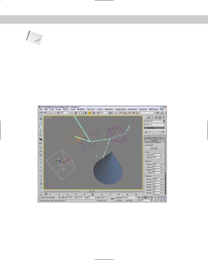
Chapter 38 Using Space Warps 927
Note |
If the Refracts value is set to 100 percent, no particles are available to be refracted. |
You can also specify Friction and Inherit Velocity values. In the Spawn Effects Only section, the Spawns and Pass Velocity values control how many particle spawns are available and their velocity upon entering the struck object. Figure 38-12 shows each of these Space Warps bound to a Super Spray particle system. The Reflect percentage for each of the Space Warps is set to 50, and the remaining particles are refracted through the Space Warp’s plane. Notice that the particles are also reflecting off the opposite side of the refracting object.
Deflector, SDeflector, and UDeflector
The Deflector and SDeflector Space Warps are simplified versions of the POmniFlect and SOmniFlect Space Warps. Their parameters include values for Bounce, Variation, Chaos, Friction, and Inherit Velocity. The UDeflector Space Warp is a simplified version of the UOmniFlect Space Warp. It has a Pick Object button for selecting the object to act as the deflector and all the same parameters as the SDeflector Space Warp.
Figure 38-12: The POmniFlect, SOmniFlect, and UOmniFlect Space Warps reflecting and refracting particles emitted from the Super Spray particle system
928 Part IX Dynamics
Geometric/Deformable Space Warps
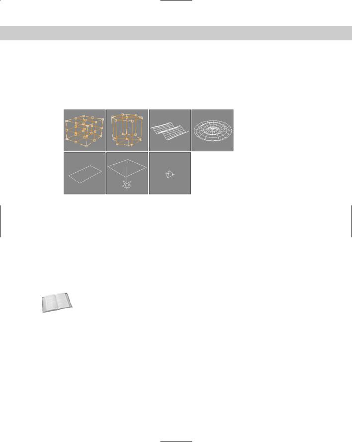
You use Geometric/Deformable Space Warps to deform the geometry of an object. Space Warps in this subcategory include FFD (Box), FFD (Cyl), Wave, Ripple, Displace, Conform, and Bomb. These Space Warps can be applied to any deformable object. Figure 38-13 shows the icons for each of these Space Warps.
Figure 38-13: The Geometric/Deformable Space Warps: FFD (Box),
FFD (Cyl), Wave, Ripple, Displace, Conform, and Bomb
FFD (Box) and FFD (Cyl)
The FFD (Box) and FFD (Cyl) Space Warps show up as a lattice of control points in the shape of a box and a cylinder; you can select and move the control points that make up the Space Warp to deform an object that is bound to the Space Warp. The object is deformed only if the bound object is within the volume of the Space Warp.
These Space Warps have the same parameters as the modifiers with the same name found in the Modifiers Free Form Deformers menu. The difference is that the Space Warps act in World coordinates and aren’t tied to a specific object. This makes it so a single FFD Space Warp can affect multiple objects.
Cross- |
To learn about the FFD (Box) and FFD (Cyl) modifiers, see Chapter 11, “Introducing Modifiers |
Reference |
for Basic Object Deformation.” |
|
To move the control points, select the Space Warp object, open the Modify panel, and select the Control Points subobject, which lets you alter the control points individually.
FFD Select modifier
The FFD Select modifier is another unique selection modifier. It enables you to select a group of control point subobjects for the FFD (Box) or the FFD (Cyl) Space Warps and apply additional modifiers to the selection. When an FFD Space Warp is applied to an object, you can select the Control Points subobjects and apply modifiers to the selection. The FFD Select modifier lets you select a different set of control points for a different modifier.
Chapter 38 Using Space Warps 929
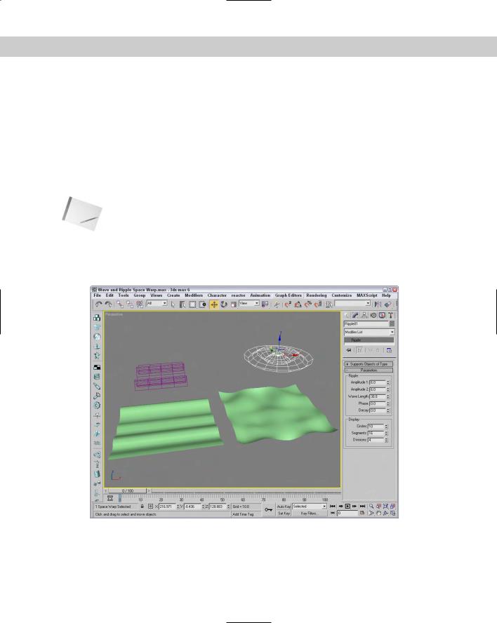
Wave and Ripple
The Wave and Ripple Space Warps create linear and radial waves in the objects to which they are bound. Parameters in the rollout help define the shape of the wave. Amplitude 1 is the wave’s height along the X axis, and Amplitude 2 is the wave’s height along its Y axis. The Wave Length value defines how long each wave is. The Phase value determines how the wave starts at its origin. The Decay value sets how quickly the wave dies out. A Decay value of 0 maintains the same amplitude for the entire wave.
The Sides (Circles) and Segments values determine the number of segments for the X and Y axes. The Division value changes the icon’s size without altering the wave effect. Figure 38-14 shows a Wave Space Warp applied to a simple Box primitive. Notice that the Space Warp icon is smaller than the box, yet it affects the entire object.
Note |
Be sure to include enough segments in the bound object, or the effect won’t be visible. |
Tutorial: Creating pond ripples
For this tutorial, we position a patch object so it aligns with a background image and apply the Ripple Space Warp to it.
Figure 38-14: The Wave and Ripple Space Warps applied to a patch grid object
930 Part IX Dynamics
To add ripples to a pond, follow these steps:
1.Open the Pond ripple.max file from the Chap 38 directory on the CD-ROM.
This file includes a background image or a bridge matched to a patch grid where the pond is located with a reflective material assigned to it.
2.Select the Create Space Warps Geometric/Deformable Ripple menu command. Drag in the Perspective view to create a Space Warp object. In the Parameters rollout, set the Amplitudes to 2 and the Wave Length to 30.
3.Click the Bind to Space Warp button, and drag from the patch object to the Space Warp. Figure 38-15 shows the resulting image.
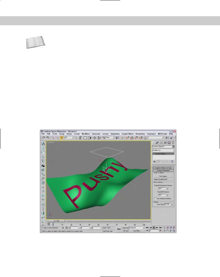
Conform
The Conform Space Warp pushes all object vertices until they hit another target object called the Wrap To Object, or until they’ve moved a preset amount. The Conform Parameters rollout includes a Pick Object button that lets you pick the Wrap To Object. The object vertices move no farther than this Wrap To Object.
You can also specify a Default Projection Distance and a Standoff Distance. The Default Projection Distance is the maximum distance that the vertices move if they don’t intersect with the Wrap To Object. The Standoff Distance is the separation amount maintained between the Wrap To Object and the moved vertices. There is also an option to Use Selected Vertices that moves only a subobject selection.
Figure 38-15: A ripple in a pond produced using the Ripple Space Warp
Chapter 38 Using Space Warps 931
Cross- |
The Conform Space Warp is similar in function to the Conform compound object that is cov- |
Reference |
ered in Chapter 17, “Building Compound Objects.” |
|
Figure 38-16 shows some text being deformed with the Conform Space Warp. A warped quad patch has been selected as the Wrap To Object.
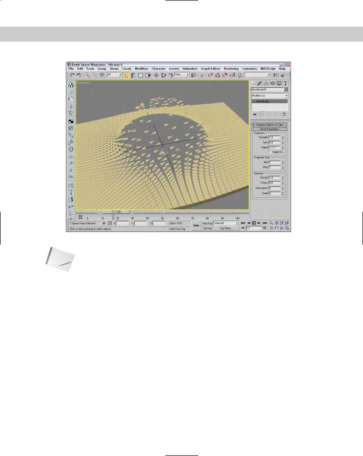
Bomb
The Bomb Space Warp causes an object to explode from its individual faces. The Strength value is the power of the bomb and determines how far objects travel when exploded. The Spin value is the rate at which the individual pieces rotate. The Falloff value defines the boundaries of faces affected by the bomb. Object faces beyond this distance remain unaffected. You must select Falloff On for the Falloff value to work.
The Min and Max Fragment Size values set the minimum and maximum number of faces caused by the explosion.
The Gravity value determines the strength of gravity and can be positive or negative. Gravity always points toward the world’s Z axis. The Chaos value can range between 0 and 10 to add variety to the explosion. The Detonation value is the number of the frame where the explosion should take place, and the Seed value alters the randomness of the event. Figure 38-17 shows frame 20 of an explosion produced by the Bomb Space Warp.
Figure 38-16: The Conform Space Warp wraps the surface of one object around another object.
932 Part IX Dynamics
Figure 38-17: The Bomb Space Warp causes an object to explode.
Note |
The Bomb Space Warp is seen over time. At frame 0, the object shows no effect. |
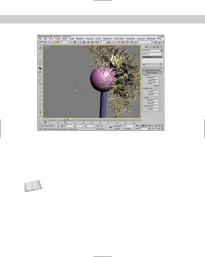
Tutorial: Blowing a dandelion puff
You can use Space Warps with other types of objects besides particle systems. The Scatter object, for example, can quickly create many unique objects that can be controlled by a Space Warp. In this tutorial, we create a simple, crude dandelion puff that can blow away in the wind.
To create and blow away a dandelion puff, follow these steps:
1.Open the Dandelion puff.max file from the Chap 38 directory on the CD-ROM.
This file includes a sphere covered with a Scatter compound object representing the seeds of a dandelion.
2.Select the Create Space Warps Geometric/Deformable Bomb menu command. Click in the Front viewport, and position the Bomb icon to the left and slightly below the dandelion object. In the Bomb Parameters rollout, set the Strength to 10, the Spin to 100, and the Min and Max Fragment Size values to 24.
This is the total number of faces included in the dandelion object.
3.Click the Bind to Space Warp button on the main toolbar, and drag from the dandelion object to the Space Warp.
Figure 38-18 shows one frame of the dandelion puff being blown away.
Chapter 38 Using Space Warps 933
Figure 38-18: You can use Space Warps on Scatter objects as well as particle systems.
Modifier-Based Space Warps
Modifier-Based Space Warps produce the same effects as many of the standard modifiers, but because they are Space Warps, they can be applied to many objects simultaneously. Space Warps in this subcategory include Bend, Noise, Skew, Taper, Twist, and Stretch (see Figure 38-19). All Modifier-Based Space Warp gizmos are simple box shapes. The parameters for all Modifier-Based Space Warps are identical to the modifiers of the same name. These Space Warps don’t include a Supports Objects of Type rollout because they can be applied to all objects.
Cross- |
For details on the Bend, Noise, Skew, Taper, Twist, and Stretch modifiers and their param- |
Reference |
eters, see Chapter 11, “Introducing Modifiers for Basic Object Deformation.” |
|
These Space Warps include a Gizmo Parameters rollout with values for the Length, Width, and Height of the gizmo. You can also specify the deformation decay. The Decay value causes the Space Warp’s effect to diminish with distance from the bound object.
You can reposition the Modifier-Based Space Warp’s gizmo as a separate object, but the normal modifiers require that you select the gizmo subobject in order to reposition it. Unlike modifiers, Space Warps don’t have any subobjects.