

Beginning Visual C++ 2005 (2006) [eng]-1
.pdfDrawing in a Window
You create a pen in the way you saw earlier, only this time you make sure that the creation works. In the unlikely event that it doesn’t, the most likely cause is that you’re running out of memory, which is a serious problem. This is almost invariably caused by an error in the program, so you have written the function to call AfxMessageBox(), which is a global function to display a message box, and then call AfxAbort() to terminate the program. The first argument to AfxMessageBox() specifies the message that is to appear, and the second specifies that it should have an OK button. You can get more information on either of these functions by placing the cursor within the function name in the editor window and then pressing F1.
After selecting the pen, you move the current position to the start of the line, defined in the inherited m_StartPoint data member, and then draw the line from this point to the end point. Finally, you restore the old pen in the device context and you are done. The m_Pen variable that is the second argument to the CreatePen() function does not exist yet; you’ll add this to the CElement class a little later in this chapter.
Creating Bounding Rectangles
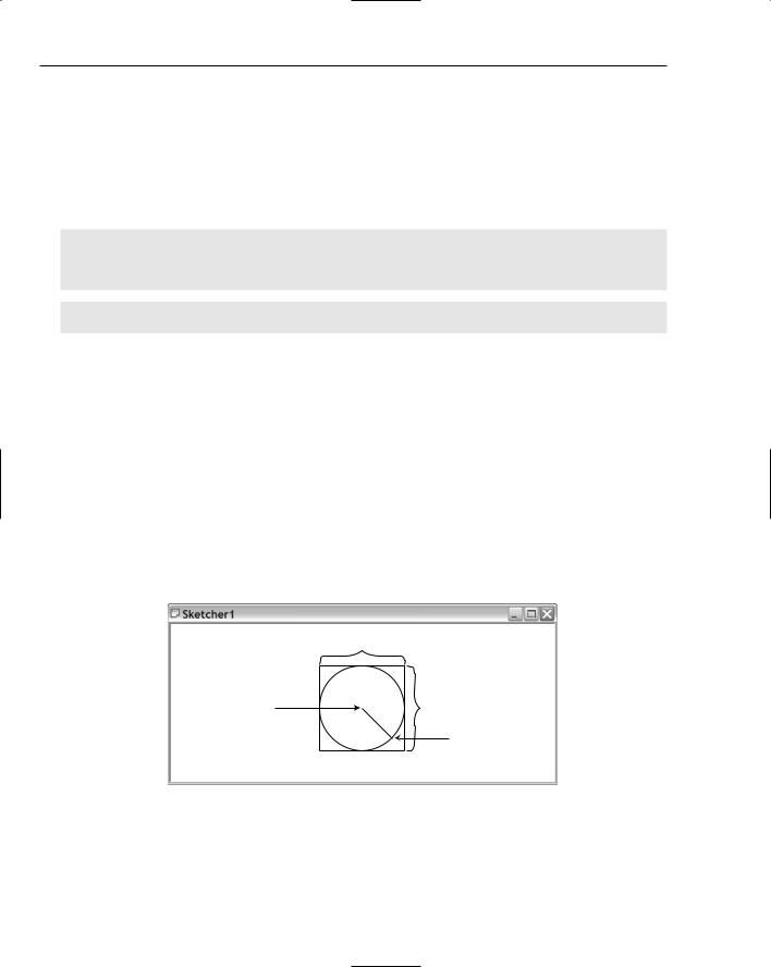
At first sight, obtaining the bounding rectangle for a shape looks trivial. For example, a line is always a diagonal of its enclosing rectangle, and a circle is defined by its enclosing rectangle, but there are a couple of slight complications. The shape must lie completely inside the rectangle; otherwise, part of the shape may not be drawn, so you must allow for the thickness of the line used to draw the shape when you create the bounding rectangle. Also, how you work out adjustments to the coordinates that define the bounding rectangle depends on the mapping mode, so you must take that into account too.
Look at Figure 14-17, which relates to the method for obtaining the bounding rectangle for a line and a circle.
 Negative X-Axis
Negative |
Negative |
|
|
Negative |
Positive |
|
|
|
|
|
|
|
|
|
Bounding |
|
|
|
|
|
|
|
|
|
|||
|
|
|
|
|
|
|
|
|
rectangles |
|
|
|
|
|
|
|
|
|
|
|
|
|
|
|
|
|
|
|
|
|
|
|
|
|
|
|
|
|
|
|
|
|
|
|
|
|
|
|
|
|
|
|
|
|
|
|
|
|
|
|
|
|
|
|
|
|
|
|
|
|
Positive |
|
|
|
|
|
|
|
|
|
|
|
|
|
|||
|
|
|
|
|
|
|
|
|
|
|
|
|
|
|
|
Positive |
|||||
|
|
Enclosing rectangle for the line |
Enclosing rectangle for the circle |
||||||||||||||||||
Positive Y-Axis |
|
|
|
|
MM_TEXT |
|
|
|
|
|
|
|
|
|
|||||||
|
|
|
|
|
|
Positive X-Axis |
|
|
|
Positive |
|||||||||||
|
|
|
|
|
|
|
|
|
|||||||||||||
|
|
|
|
|
Positive |
|
|
|
|
|
|
|
|||||||||
|
|
|
|
|
|
|
|
|
Negative |
|
|
|
|
|
|
|
|
|
Positive |
||
|
|
|
|
|
|
|
|
|
|
|
|
|
|
|
|
|
|
|
|||
|
|
|
|
|
|
|
|
|
Bounding |
|
|
|
|
|
|
|
|
|
|||
|
|
|
|
|
|
|
|
|
rectangles |
|
|
|
|
|
|
|
|
|
|
|
|
|
|
|
|
|
|
|
|
|
|
|
|
|
|
|
|
|
|
|
|
|
|
|
|
|
|
|
|
|
|
|
|
|
|
|
|
|
|
|
|
|
|
||
|
|
|
|
|
|
|
|
|
|
|
|
|
|
|
|
|
|
|
|
|
|
|
|
|
|
|
Negative |
|
|
|
|
|
|
|
|
|
|
|
|
|
|||
|
|
|
|
|
|
|
|
|
|
|
|
|
|
|
|
Negative |
|||||
|
|
Enclosing rectangle for the line |
Enclosing rectangle for the circle |
||||||||||||||||||
Negative Y-Axis |
|
|
MM_LOENGLISH |
|
|
|
|
|
|
|
|
|
|||||||||
Figure 14-17
739

Chapter 14
I have called the rectangle that is used to draw a shape the ‘enclosing rectangle,’ while the rectangle that takes into account the width of the pen I’ve called the ‘bounding rectangle’ to differentiate it. Figure 14-17 shows the shapes with their enclosing rectangles, and their bounding rectangles offset by the line thickness. This is obviously exaggerated here so you can see what’s happening.
The differences in how you calculate the coordinates for the bounding rectangle in different mapping modes only concerns the y coordinate; calculation of the x coordinate is the same for all mapping modes. To get the corners of the bounding rectangle in the MM_TEXT mapping mode, subtract the line thickness from the y coordinate of the upper-left corner of the defining rectangle, and add it to the y coordinate of the lower-right corner. However, in MM_LOENGLISH (and all the other mapping modes), the y axis increases in the opposite direction, so you need to add the line thickness to the y coordinate of the upper-left corner of the defining rectangle, and subtract it from the y coordinate of the lower-right corner. For all the mapping modes, you subtract the line thickness from the x coordinate of the upper-left corner of the defining rectangle, and add it to the x coordinate of the lower-right corner.
To implement the element types as consistently as possible in Sketcher, you could store an enclosing rectangle for each shape in a member in the base class. The enclosing rectangle needs to be calculated when a shape is constructed. The job of the GetBoundRect() function in the base class will then be to calculate the bounding rectangle by offsetting the enclosing rectangle by the pen width. You can amend the CElement class definition by adding two data members, as follows:
class CElement: public CObject |
|
|
{ |
|
|
protected: |
|
|
COLORREF m_Color; |
|
// Color of an element |
CRect m_EnclosingRect; |
|
// Rectangle enclosing an element |
int m_Pen; |
|
// Pen width |
public: |
|
|
virtual ~CElement(); |
|
// Virtual destructor |
virtual void Draw(CDC* pDC) {} |
// Virtual draw operation |
|
CRect GetBoundRect(); |
// Get the bounding rectangle for an element |
|
protected: |
|
|
CElement(); |
|
// Here to prevent it being called |
}; |
|
|
You can add these by right-clicking on the class name and selecting Add Member Variable from the popup, or you can add the statements directly in the Editor window along with the comments.
You must also update the CLine constructor so that it has the correct pen width:
// CLine class constructor
CLine::CLine(CPoint Start, CPoint End, COLORREF aColor)
{
m_StartPoint = Start; m_EndPoint = End; m_Color = aColor; m_Pen = 1;
//Set line start point
//Set line start point
//Set line color
//Set pen width
}
740

Drawing in a Window
You can now implement the GetBoundRect() member of the base class, assuming the MM_TEXT mapping mode:
// Get the bounding rectangle for an element
CRect CElement::GetBoundRect() |
|
{ |
|
CRect BoundingRect; |
// Object to store bounding rectangle |
BoundingRect = m_EnclosingRect; |
// Store the enclosing rectangle |
// Increase the rectangle by the pen width BoundingRect.InflateRect(m_Pen, m_Pen);
return BoundingRect; |
// Return the bounding rectangle |
} |
|
This returns the bounding rectangle for any derived class object. You define the bounding rectangle by modifying the coordinates of the enclosing rectangle stored in the base class data member so that it is enlarged all round by the pen width, using the InflateRect() method of the CRect class.
The CRect class provides an operator + for rectangles, which you could have used instead. For example, you could have written the statement before the return as:
BoundingRect = m_EnclosingRect + CRect(m_Pen, m_Pen, m_Pen, m_Pen);
Equally, you could have simply added (or subtracted) the pen width for each of the x and y values that make up the rectangle. You could have replaced the assignment with the following statements:
BoundingRect = m_EnclosingRect;
BoundingRect.top -= m_Pen;
BoundingRect.left -= m_Pen;
BoundingRect.bottom += m_Pen;
BoundingRect.right += m_Pen;
As a reminder, the individual data members of a CRect object are left and top (storing the x and y coordinates of the upper-left corner) and right and bottom (storing the coordinates of the lower-right corner). These are all public members, so you can access them directly. A commonly made mistake, especially by me, is to write the coordinate pair as (top,left) instead of in the correct order (left,top).
The hazard with both this and the InflateRect() option is that there is a built-in assumption that the mapping mode is MM_TEXT, which means that the positive y axis is assumed to run from top to bottom. If you change the mapping mode, neither of these will work properly, although it’s not immediately obvious that they won’t.
Normalized Rectangles
The InflateRect() function works by subtracting the values that you give it from the top and left members of the rectangle and adding the values to the bottom and right. This means that you may find your rectangle actually decreasing in size if you don’t make sure that the rectangle is normalized. A normalized rectangle has a left value that is less than or equal to the right value, and a top value that is less than or equal to the bottom value. You can make sure that a CRect object is normalized by calling the NormalizeRect() member of the object. Most of the CRect member functions require the object to be normalized for them to work as expected, so you need to make sure that when you store the enclosing rectangle in m_EnclosingRect, it is normalized.
741

Chapter 14
Calculating the Enclosing Rectangle for a Line
All you need now is code in the constructor for a line to calculate the enclosing rectangle:
CLine::CLine(CPoint Start, CPoint End, COLORREF aColor)
{
m_StartPoint = Start; |
// Set |
line start point |
m_EndPoint = End; |
// Set |
line end point |
m_Color = aColor; |
// Set |
line color |
m_Pen = 1; |
// Set |
pen width |
// Define the enclosing rectangle m_EnclosingRect = CRect(Start, End); m_EnclosingRect.NormalizeRect();
}
The arguments to the CRect constructor you are using here are the start and end points of the line. To ensure that the bounding rectangle has the top value less than the bottom value, regardless of the relative positions of the start and end points of the line you call the NormalizeRect() member of the m_EnclosingRect object.
The CRectangle Class
Although you’ll be defining a rectangle object by the same data that you use to define a line(a start point and an end point on a diagonal of the rectangle(you don’t need to store the defining points. The enclosing rectangle in the data member inherited from the base class completely defines the shape, so you don’t need any data members. You can therefore define the class like this:
// Class defining a rectangle object |
|
class CRectangle: public CElement |
|
{ |
|
public: |
|
~CRectangle(void); |
|
virtual void Draw(CDC* pDC); |
// Function to display a rectangle |
// Constructor for a rectangle object CRectangle(CPoint Start, CPoint End, COLORREF aColor);
protected: |
|
CRectangle(void); |
// Default constructor - should not be used |
}; |
|
The no-arg constructor is now protected to prevent it from being used. The definition of the rectangle becomes very simple — just a constructor, the virtual Draw() function, plus the no-arg constructor in the protected section of the class.
The CRectangle Class Constructor
The code for the new CRectangle class constructor is somewhat similar to that for a CLine constructor:
// CRectangle class constructor
CRectangle:: CRectangle(CPoint Start, CPoint End, COLORREF aColor)
{
742

Drawing in a Window
m_Color |
= aColor; |
// |
Set |
rectangle color |
m_Pen = |
1; |
// |
Set |
pen width |
// Define the enclosing rectangle m_EnclosingRect = CRect(Start, End); m_EnclosingRect.NormalizeRect();
}
If you modified the CRectangle class definition manually, there is no skeleton definition for the constructor, so you just need to add the definition directly to Elements.cpp.
This is cheap code. Some minor alterations to a subset of the CLine constructor, fix the comments, and we have a new constructor for CRectangle. It just stores the color and pen width and computes the enclosing rectangle from the points passed as arguments.
Drawing a Rectangle
There is a member of the CDC class called Rectangle() that draws a rectangle. This function draws a closed figure and fills it with the current brush. You may think that this isn’t quite what you want because you want to draw rectangles as outlines only, but by selecting a NULL_BRUSH that is exactly what you will draw. Just so you know, there’s also a function PolyLine(), which draws shapes consisting of multiple line segments from an array of points, or you could have used LineTo() again, but the easiest approach is to use the Rectangle() function:
// Draw a CRectangle object void CRectangle::Draw(CDC* pDC)
{
//Create a pen for this object and
//initialize it to the object color and line width of 1 pixel CPen aPen;
if(!aPen.CreatePen(PS_SOLID, m_Pen, m_Color))
{
// Pen creation failed
AfxMessageBox(_T(“Pen creation failed drawing a rectangle”), MB_OK); AfxAbort();
}
// Select the pen
CPen* pOldPen = pDC->SelectObject(&aPen); // Select the brush
CBrush* pOldBrush = (CBrush*)pDC->SelectStockObject(NULL_BRUSH);
// Now draw the rectangle pDC->Rectangle(m_EnclosingRect);
pDC->SelectObject(pOldBrush); |
// |
Restore |
the |
old |
brush |
pDC->SelectObject(pOldPen); |
// |
Restore |
the |
old |
pen |
}
After setting up the pen and the brush, you simply pass the whole rectangle directly to the Rectangle() function to get it drawn. All that remains to do is to clear up afterwards and restore the device context’s old pen and brush.
743
Chapter 14
The CCircle Class
The interface of the CCircle class is no different from that of the CRectangle class. You can define a circle solely by its enclosing rectangle, so the class definition is:
// Class defining a circle object |
|
class CCircle: public CElement |
|
{ |
|
public: |
|
~CCircle(void); |
|
virtual void Draw(CDC* pDC); |
// Function to display a circle |
// Constructor for a circle object
CCircle(CPoint Start, CPoint End, COLORREF aColor);
protected:
CCircle(void); |
// Default constructor - should not be used |
}; |
|
You have defined a public constructor that creates a circle from two points, and makes the no-arg constructor as protected again. You have also added a declaration for the draw function to the class definition.
Implementing the CCircle Class
As I discussed earlier, when you create a circle, the point where you press the left mouse button is the center, and after moving the cursor with the left button down, the point where you release the cursor is a point on the circumference of the final circle. The job of the constructor is to convert these points into the form used in the class to define a circle.
The CCircle Class Constructor
The point at which you release the left mouse button can be anywhere on the circumference, so the coordinates of the points specifying the enclosing rectangle need to be calculated, as illustrated in Figure 14-18.
|
This distance is 2r |
|
Left mouse |
x1,y1 |
This distance is 2r |
button down |
|
|
here |
Radius r |
Left mouse |
|
||
|
|
|
|
|
button up here |
x2,y2
r2=(x2–x1)2+(y2–y1)2
Figure 14-18
From Figure 14-18 you can see that you can calculate the coordinates of the upper-left and lower-right points of the enclosing rectangle relative to the center of the circle (x1, y1), which is the point you record when the left mouse button is pressed. Assuming that the mapping mode is MM_TEXT, for the upper-left
744

Drawing in a Window
point you just subtract the radius from each of the coordinates of the center. Similarly, the lower-right point is obtained by adding the radius to the x and y coordinates of the center. You can, therefore, code the constructor as:
// Constructor for a circle object
CCircle::CCircle(CPoint Start, CPoint End, COLORREF aColor)
{
//First calculate the radius
//We use floating point because that is required by
//the library function (in math.h) for calculating a square root. long Radius = static_cast<long> (sqrt(
static_cast<double>((End.x-Start.x)*(End.x-Start.x)+ (End.y-Start.y)*(End.y-Start.y))));
//Now calculate the rectangle enclosing
//the circle assuming the MM_TEXT mapping mode
m_EnclosingRect = CRect(Start.x-Radius, Start.y-Radius,
Start.x+Radius, Start.y+Radius);
m_Color |
= aColor; |
// |
Set |
the |
color |
for the circle |
m_Pen = |
1; |
// |
Set |
pen |
width |
to 1 |
}
To use the sqrt() function, you must add the line to the beginning of the Elements.cpp file:
#include <math.h>
You can place this after the #include directive for stdafx.h.
The maximum coordinate values are 32 bits, and the CPoint members x and y are declared as long, so evaluating the argument to the sqrt() function can safely be carried out as an integer. The result of the square root calculation is of type double, so you cast it to long because you want to use it as an integer.
Drawing a Circle
You have already seen how to draw a circle using the Arc() function in the CDC class, so now use the Ellipse() function here. The implementation of the Draw() function in the CCircle class is:
// Draw a circle
void CCircle::Draw(CDC* pDC)
{
//Create a pen for this object and
//initialize it to the object color and line width of 1 pixel CPen aPen;
if(!aPen.CreatePen(PS_SOLID, m_Pen, m_Color))
{
// Pen creation failed
AfxMessageBox(_T(“Pen creation failed drawing a circle”), MB_OK); AfxAbort();
}
CPen* pOldPen = pDC->SelectObject(&aPen); // Select the pen
// Select a null brush
745

Chapter 14
CBrush* pOldBrush = (CBrush*)pDC->SelectStockObject(NULL_BRUSH);
// Now draw the circle pDC->Ellipse(m_EnclosingRect);
pDC->SelectObject(pOldPen); |
// |
Restore |
the |
old |
pen |
pDC->SelectObject(pOldBrush); |
// |
Restore |
the |
old |
brush |
}
After selecting a pen of the appropriate color and a null brush, the circle is drawn by calling the Ellipse() function. The only argument is a CRect object that encloses the circle you draw. This is another example of code that’s almost for free because it’s similar to the code you wrote earlier to draw a rectangle.
The CCurve Class
The CCurve class is different from the others in that it needs to be able to deal with a variable number of defining points. This necessitates maintaining a list of some kind, and because you will look at how you can deal with lists of arbitrary length in the next chapter, I’ll defer defining the detail of this class until then. For now, you can include a class definition that provides dummy member functions so you can compile and link code that contains calls to them. In Elements.h, you should have:
class CCurve: public CElement
{
public:
~CCurve(void);
virtual void Draw(CDC* pDC); // Function to display a curve
// Constructor for a curve object CCurve(COLORREF aColor);
protected: |
|
CCurve(void); |
// Default constructor - should not be used |
};
And in Elements.cpp:
//Constructor for a curve object CCurve::CCurve(COLORREF aColor)
{
m_Color = aColor; m_EnclosingRect = CRect(0,0,0,0); m_Pen = 1;
}
//Draw a curve
void CCurve::Draw(CDC* pDC)
{
}
Neither the constructor nor the Draw() member function does anything useful yet, and you have no data members to define a curve. The constructor just sets the color, sets m_EnclosingRect to an empty rectangle, and sets the pen width. You’ll expand the class into a working version in the next chapter.
746

Drawing in a Window
Completing the Mouse Message Handlers
You can now come back to the WM_MOUSEMOVE message handler and fill out the detail. You can get to it through selecting CSketcherView in the Class View and double-clicking the handler name,
OnMouseMove().
This handler is concerned only with drawing a succession of temporary versions of an element as you move the cursor because the final element is created when you release the left mouse button. You can therefore treat the drawing of temporary elements to provide rubber-banding as being entirely local to this function, leaving the final version of the element that is created to be drawn by the OnDraw() function member of the view. This approach results in the drawing of the rubber-banded elements being reasonably efficient because it won’t involve the OnDraw() function that ultimately is responsible for drawing the entire document.
You can do this best with the help of a member of the CDC class that is particularly effective in rubberbanding operations: SetROP2().
Setting the Drawing Mode
The SetROP2() function sets the drawing mode for all subsequent output operations in the device context associated with a CDC object. The ‘ROP’ bit of the function name stands for Raster OPeration because the setting of drawing modes applies to raster displays. In case you’re wondering, ‘What’s SetROP1() then?’ — there isn’t one. The function name represents ‘Set Raster OPeration to’, not 2!
The drawing mode determines how the color of the pen that you use for drawing is to combine with the background color to produce the color of the entity you are displaying. You specify the drawing mode with a single argument to the function that can be any of the following values:
Drawing Mode |
Effect |
|
|
R2_BLACK |
All drawing is in black. |
R2_WHITE |
All drawing is in white. |
R2_NOP |
Drawing operations do nothing. |
R2_NOT |
Drawing is in the inverse of the screen color. This ensures the output |
|
is always visible because it prevents drawing in the same color as the |
|
background. |
R2_COPYPEN |
Drawing is in the pen color. This is the default drawing mode if you |
|
don’t set it. |
R2_NOTCOPYPEN |
Drawing is in the inverse of the pen color. |
R2_MERGEPENNOT |
Drawing is in the color produced by ORing the pen color with the |
|
inverse of the background color. |
R2_MASKPENNOT |
Drawing is in the color produced by ANDing the pen color with the |
|
inverse of the background color. |
R2_MERGENOTPEN |
Drawing is in the color produced by ORing the background color |
|
with the inverse of the pen color. |
|
Table continued on following page |
747

Chapter 14
Drawing Mode |
Effect |
|
|
R2_MASKNOTPEN |
Drawing is in the color produced by ANDing the background |
|
color with the inverse of the pen color. |
R2_MERGEPEN |
Drawing is in the color produced by ORing the background |
|
color with the pen color. |
R2_NOTMERGEPEN |
Drawing is in the color that is the inverse of the R2_MERGEPEN |
|
color. |
R2_MASKPEN |
Drawing is in the color produced by ANDing the background |
|
color with the pen color. |
R2_NOTMASKPEN |
Drawing is in the color that is the inverse of the R2_MASKPEN |
|
color. |
R2_XORPEN |
Drawing is in the color produced by exclusive ORing the pen |
|
color and the background color. |
R2_NOTXORPEN |
Drawing is in the color that is the inverse of the R2_XORPEN |
|
color. |
|
|
Each of these symbols is predefined and corresponds to a particular drawing mode. There are a lot of options here, but the one that can work some magic for us is the last of them, R2_NOTXORPEN.
When you set the mode as R2_NOTXORPEN, the first time you draw a particular shape on the default white background, it is drawn normally in the pen color you specify. If you draw the same shape again, overwriting the first, the shape disappears because the color that the shape is drawn in corresponds to that produced by exclusive ORing the pen color with itself. The drawing color that results from this is white. You can see this more clearly by working through an example.
White is formed from equal proportions of the “maximum” amounts of red, blue, and green. For simplicity, this can be represented as 1,1,1 — the three values represent the RGB components of the color. In the same scheme, red is defined as 1,0,0. These combine as follows:
|
R |
G |
B |
|
|
|
|
Background — white |
1 |
1 |
1 |
Pen — red |
1 |
0 |
0 |
XORed |
0 |
1 |
1 |
NOT XOR — produces red |
1 |
0 |
0 |
|
|
|
|
So, the first time you draw a red line on a white background, it comes out red as the last line above indicates. If you now draw the same line a second time, overwriting the existing line, the background pixels you are writing over are red. The resultant drawing color works out as follows:
748