

Beginning Visual C++ 2005 (2006) [eng]-1
.pdfDrawing in a Window
The Windows Graphical Device Interface
The final constraint Windows imposes is that you don’t actually write data to the screen in any direct sense. All output to your display screen is graphical, regardless of whether it is lines and circles, or text. Windows insists that you define this output using the Graphical Device Interface (GDI). The GDI enables you to program graphical output independently of the hardware on which it is displayed, meaning that your program works on different machines with different display hardware. In addition to display screens, the Windows GDI also supports printers and plotters, so outputting data to a printer or a plotter involves essentially the same mechanisms as displaying information onscreen.
What Is a Device Context?
When you want to draw something on a graphical output device such as the display screen, you must use a device context. A device context is a data structure that’s defined by Windows and contains information that allows Windows to translate your output requests, which are in the form of device-independent GDI function calls, into actions on the particular physical output device being used. A pointer to a device context is obtained by calling a Windows API function.
A device context provides you with a choice of coordinate systems called mapping modes, which is automatically converted to client coordinates. You can also alter many of the parameters that affect the output to a device context by calling GDI functions; such parameters are called attributes. Examples of attributes that you can change are the drawing color, the background color, the line thickness to be used when drawing and the font for text output. There are also GDI functions that provide information about the physical device with which you’re working. For example, you may need to be certain that the display on the computer executing your program can support 256 colors, or that a printer can support the output of bitmaps.
Mapping Modes
Each mapping mode in a device context is identified by an ID, in a manner similar to what we saw with Windows messages. Each symbol has the prefix MM_ to indicate that it defines a mapping mode. The mapping modes provided by Windows are:
Mapping Mode |
Description |
|
|
MM_TEXT |
A logical unit is one device pixel with positive x from left to right, and |
|
positive y from top to bottom of the window client area. |
MM_LOENGLISH |
A logical unit is 0.01 inches with positive x from left to right, and posi- |
|
tive y from the top of the client area upwards. |
MM_HIENGLISH |
A logical unit is 0.001 inches with the x and y directions as in |
|
MM_LOENGLISH. |
MM_LOMETRIC |
A logical unit is 0.1 millimeters with the x and y directions as in |
|
MM_LOENGLISH. |
MM_HIMETRIC |
A logical unit is 0.01 millimeters with the x and y directions as in |
|
MM_LOENGLISH. |
MM_ISOTROPIC |
A logical unit is of arbitrary length, but the same along both the x and y |
|
axes. The x and y directions are as in MM_LOENGLISH. |
|
Table continued on following page |
709

Chapter 14
Mapping Mode |
Description |
|
|
MM_ANISOTROPIC |
This mode is similar to MM_ISOTROPIC, but allows the length of a logical |
|
unit on the x axis to be different from that of a logical unit on the y axis. |
MM_TWIPS |
A logical unit is a TWIP where a TWIP is 0.05 of a point and a point is 1⁄72 |
|
of an inch. Thus a TWIP corresponds to 1⁄1440 of an inch, which is 6.9x10⁻⁴ |
|
of an inch. (A point is a unit of measurement for fonts.) The x and y |
|
directions are as in MM_LOENGLISH. |
|
|
You’re not going to be using all of these mapping modes with this book; however, the ones you will use form a good cross-section of those available, so you won’t have any problem using the others when you need to.
MM_TEXT is the default mapping mode for a device context. If you need to use a different mapping mode, you have to take steps to change it. Note that the direction of the positive y axis in the MM_TEXT mode is opposite to what you saw in high school coordinate geometry, as shown in Figure 14-2.
Positive x direction
MM_TEXT mapping mode
Positive y direction
Figure 14-2
By default, the point at the upper-left corner of the client area has the coordinates (0,0) in every mapping mode, although it’s possible to move the origin away from the upper-left corner of the client area if you want to. For example, some applications that present data in graphical form move the origin to the center of the client area to make plotting of the data easier. With the origin at the upper-left corner in MM_TEXT mode, a point 50 pixels from the left border and 100 pixels down from the top of the client area will have the coordinates (50,100). Of course, because the units are pixels, the point will be nearer the upper-left corner of the client area if your monitor is set to use a resolution of 1280x1024 than if it’s working with the resolution set as 1024x768. An object drawn in this mapping mode will be smaller at the 1280x1024 resolution than it would be at the 1024x768 resolution. Note that the DPI setting for your display affects presentation in all mapping modes. The default settings assume 96 DPI, so if the DPI for your display is set to a different value, this affects how thing look. Coordinates are always 32-bit signed integers unless you are programming for the old Windows95/98 operating systems, in which case they are limited to 16 bits. The maximum physical size of the total drawing varies with the physical length of a coordinate unit, which is determined by the mapping mode.
710

Drawing in a Window
The directions of the x and y coordinate axes in MM_LOENGLISH and all the remaining mapping modes are the same as each other, but different from MM_TEXT. The coordinate axes for MM_LOENGLISH are shown in Figure 14-3. Although positive y is consistent with what you learned in high school (y values increase as you move up the screen), MM_LOENGLISH is still slightly odd because the origin is at the upper-left corner of the client area, so for points within the visible client area, y is always negative.
Positive x direction
MM_LOENGLISH mapping mode
Negative y direction
Figure 14-3
In the MM_LOENGLISH mapping mode, the units along the axes are 0.01 inches apiece, so a point at the position (50, -100) is half an inch from the left border and one inch down from the top of the client area. An object is the same size in the client area, regardless of the resolution of the monitor on which it is displayed. If you draw anything in the MM_LOENGLISH mode with negative x or positive y coordinates, it is outside the client area and therefore not visible because the reference point (0,0) is the upper-left corner by default. It’s possible to move the position of the reference point though, by calling the Windows API function SetViewportOrg() (or the SetViewportOrg() member of the CDC MFC class that I’ll discuss shortly).
The Drawing Mechanism in Visual C++
MFC encapsulates the Windows interface to your screen and printer and relieves you of the need to worry about much of the detail involved in programming graphical output. As you saw in the last chapter, the Application wizard-generated program already contains a class derived from the MFC class CView that’s specifically designed to display document data onscreen.
The View Class in Your Application
The MFC Application wizard generated the class CSketcherView to display information from a document in the client area of a document window. The class definition includes overrides for several virtual functions, but the one of particular interest in here is the function OnDraw(). This is called whenever the client area of the document window needs to be redrawn. It’s the function that’s called by the application framework when a WM_PAINT message is received in your program.
The OnDraw() Member Function
The implementation of the OnDraw() member function that’s created by the MFC Application wizard looks like this:
711

Chapter 14
void CSketcherView::OnDraw(CDC* /*pDC*/)
{
CSketcherDoc* pDoc = GetDocument(); ASSERT_VALID(pDoc);
if(!pDoc)
return;
// TODO: add draw code for native data here
}
A pointer to an object of the CDC class type is passed to the OnDraw() member of the view class. This object has member functions that call the Windows API functions and these allow you to draw in a device context. Note that the parameter name is commented out so you must uncomment the name or replace it with your own name before you can use the pointer.
Because you’ll put all the code to draw the document in this function, the Application wizard has included a declaration for the pointer pDoc and initialized it using the function GetDocument(), which returns the address of the document object related to the current view:
CSketcherDoc* pDoc = GetDocument();
The GetDocument() function actually retrieves the pointer to the document from m_pDocument, an inherited data member of the view object. The function performs the important task of casting the pointer stored in this data member to the type corresponding to the document class in the application, CSketcherDoc. This is so that the compiler has access to the members of the document class that you’ve defined; otherwise, the compiler is able to access only the members of the base class. Thus, pDoc points to the document object in your application associated with the current view, and you will be using it to access the data that you’ve stored in the document object when you want to draw it.
The following line:
ASSERT_VALID(pDoc);
just makes sure that the pointer pDoc contains a valid address and the if statement that follows ensures that pDoc is not null.
The name of the parameter pDC for the OnDraw() function stands for “pointer to Device Context.” The object of the CDC class pointed to by the pDC argument that’s passed to the OnDraw() function is the key to drawing in a window. It provides a device context, plus the tools you need to write graphics and text to it, so you clearly need to look at it in more detail.
The CDC Class
You should do all the drawing in your program using members of the CDC class. All objects of this class and classes derived from it contain a device context and the member functions you need for sending graphics and text to your display and your printer. There are also member functions for retrieving information about the physical output device that you are using.
Because CDC class objects can provide almost everything you’re likely to need by way of graphical output, there are a lot of member functions of this class — in fact, well over a hundred. Therefore, you’ll
712

Drawing in a Window
only look at the ones you’re going to use in the Sketcher program here in this chapter and go into others as you need them later on.
Note that MFC includes some more specialized classes for graphics output that are derived from CDC. For example, you be using objects of CClientDC because it is derived from CDC and contains all the members we will discuss at this point. The advantage that CClientDC has over CDC is that it always contains a device context that represents only the client area of a window, and this is precisely what you want in most circumstances.
Displaying Graphics
In a device context, you draw entities such as lines, circles, and text relative to a current position. A current position is a point in the client area that was set either by the previous entity that was drawn, or by calling a function to set it. For example, you could extend the OnDraw() function to set the current position as follows:
void CSketcherView::OnDraw(CDC* pDC)
{
CSketcherDoc* pDoc = GetDocument(); ASSERT_VALID(pDoc);
if(!pDoc)
return;
pDC->MoveTo(50, 50); // Set the current position as 50,50
}
The shaded line calls the MoveTo() function for the CDC object pointed to by pDC. This member function simply sets the current position to the x and y coordinates you specify as arguments. As you saw earlier, the default mapping mode is MM_TEXT, so the coordinates are in pixels and the current position will be set to a point 50 pixels from the inside left border of the window, and 50 pixels down from the top of the client area.
The CDC class overloads the MoveTo() function to provide flexibility over how you specify the position that you want to set as the current position. There are two versions of the function, declared in the CDC class as:
CPoint |
MoveTo(int x, int y); |
// |
Move |
to |
position |
x,y |
CPoint |
MoveTo(POINT aPoint); |
// |
Move |
to |
position |
defined by aPoint |
The first version accepts the x and y coordinates as separate arguments. The second accepts one argument of type POINT, which is a structure defined as:
typedef struct tagPOINT
{
LONG x; LONG y;
} POINT;
The coordinates are members of the struct and are of type LONG (which is type defined in the Windows API corresponding to a 32-bit signed integer). You may prefer to use a class instead of a structure, in which case you can use objects of the class CPoint anywhere that a POINT object can be used. The class CPoint has data members x and y of type LONG, and using CPoint objects has the advantage that the
713

Chapter 14
class also defines member functions that operate on CPoint and POINT objects. This may seem weird because CPoint would seem to make POINT objects obsolete, but remember that the Windows API was built before MFC was around, and POINT objects are used in the Windows API and have to be dealt with sooner or later. CPoint objects are used in examples, so you’ll have an opportunity to see some of the member functions in action.
The return value from the MoveTo() function is a CPoint object that specifies the current position as it was before the move. You might think this a little odd, but consider the situation where you want to move to a new position, draw something, and then move back. You may not know the current position before the move, and after the move occurs, it would be lost so returning the position before the move makes sure it’s available to you if you need it.
Drawing Lines
You can follow the call to MoveTo() in the OnDraw() function with a call to the function LineTo(), which draws a line in the client area from the current position to the point specified by the arguments to the LineTo() function, as illustrated in Figure 14-4.
Set the current position to here |
|
pDC->MoveTo(50,50); |
|
||
Draw a line to here |
|
pDC->MoveTo(150,100); |
|
X-Axis
50,50
150,100
Y-Axis |
Units are pixels. |
Figure 14-4
The CDC class also defines two versions of the LineTo() function that have the following prototypes:
BOOL |
LineTo(int x, int y); |
// |
Draw |
a |
line |
to |
position |
x,y |
BOOL |
LineTo(POINT aPoint); |
// |
Draw |
a |
line |
to |
position |
defined by aPoint |
This offers you the same flexibility in specifying the argument to the function as MoveTo(). You can use a CPoint object as an argument to the second version of the function. The function returns TRUE if the line was drawn and FALSE otherwise.
When the LineTo() function is executed, the current position is changed to the point specifying the end of the line. This allows you to draw a series of connected lines by just calling the LineTo() function for each line. Look at the following version of the OnDraw() function:
714

Drawing in a Window
void CSketcherView::OnDraw(CDC* pDC)
{
CSketcherDoc* pDoc = GetDocument(); ASSERT_VALID(pDoc);
if(!pDoc)
return;
pDC->MoveTo(50,50); |
// Set the current |
position |
|
pDC->LineTo(50,200); |
// Draw a vertical line down 150 units |
||
pDC->LineTo(150,200); |
// Draw a |
horizontal line right 100 units |
|
pDC->LineTo(150,50); |
// Draw a |
vertical line up 150 units |
|
pDC->LineTo(50,50); |
// Draw a |
horizontal line left 100 units |
|
}
If you plug this into the Sketcher program and execute it, it displays the document window shown in Figure 14-5.
Figure 14-5
The four calls to the LineTo() function draw the rectangle shown counterclockwise, starting with the upper-left corner. The first call uses the current position set by the MoveTo() function; the succeeding calls use the current position set by the previous LineTo() function call. You can use this to draw any figure consisting of a sequence of lines, each connected to the previous line. Of course, you are also free to use MoveTo() to change the current position at any time.
Drawing Circles
You have a choice of several function members in the CDC class for drawing circles, but they’re all designed to draw ellipses. As you know from high school geometry, a circle is a special case of an ellipse,
715

Chapter 14
with the major and minor axes equal. You can, therefore, use the member function Ellipse() to draw a circle. Like other closed shapes supported by the CDC class, the Ellipse() function fills the interior of the shape with a color that you set. The interior color is determined by a brush that is selected into the device context. The current brush in the device context determines how any closed shape is filled.
MFC provides the CBrush class that you can use to define a brush. You can set the color of a CBrush object and also define a pattern to be produced when filling a closed shape. If you want to draw a closed shape that isn’t filled, you can use a null brush, which leaves the interior of the shape empty. I’ll come back to brushes a little later in this chapter.
Another way to draw circles that aren’t filled is to use the Arc() function, which doesn’t involve brushes. This has the advantage that you can draw any arc of an ellipse, rather than the complete curve. There are two versions of this function in the CDC class, declared as:
BOOL Arc(int x1, int y1, int x2, int y2, int x3, int y3, int x4, int y4);
BOOL Arc(LPCRECT lpRect, POINT StartPt, POINT EndPt);
In the first version, (x1,y1) and (x2,y2) define the upper-left and lower-right corners of a rectangle enclosing the complete curve. If you make these coordinates into the corners of a square, the curve drawn is a segment of a circle. The points (x3,y3) and (x4,y4) define the start and end points of the segment to be drawn. The segment is drawn counterclockwise. If you make (x4,y4) identical to (x3,y3), you’ll generate a complete, apparently closed curve.
In the second version of Arc(),the enclosing rectangle is defined by a RECT object, and a pointer to this object is passed as the first argument. The function also accepts a pointer to an object of the class CRect, which has four public data members: left, top, right, and bottom. These correspond to the x and y coordinates of the upper-left and lower-right points of the rectangle respectively. The class also provides a range of function members that operate on CRect objects, and we shall be using some of these later.
The POINT objects StartPt and EndPt in the second version of Arc() define the start and end of the arc to be drawn.
Here’s some code that exercises both versions of the Arc() function:
void CSketcherView::OnDraw(CDC* pDC)
{
CSketcherDoc* pDoc = GetDocument(); ASSERT_VALID(pDoc);
if(!pDoc)
return; |
|
pDC->Arc(50,50,150,150,100,50,150,100); |
// Draw the 1st (large) circle |
// Define the bounding rectangle for the 2nd (smaller) circle |
|
CRect* pRect = new CRect(250,50,300,100); |
|
CPoint Start(275,100); |
// Arc start point |
CPoint End(250,75); |
// Arc end point |
pDC->Arc(pRect,Start, End); |
// Draw the second circle |
delete pRect; |
|
}
716
Drawing in a Window
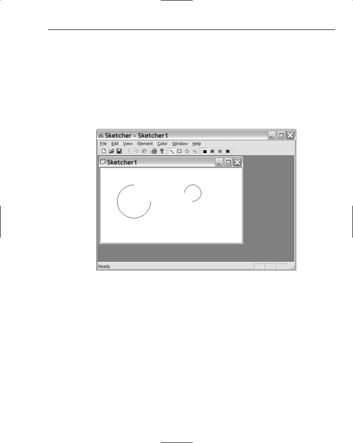
Note that you used a CRect class object instead of a RECT structure to define the bounding rectangle, and that you used CPoint class objects instead of POINT structures. You’ll also be using CRect objects later, but they have some limitations, as you’ll see. The Arc() function doesn’t require a current position to be set, as the position and size of the arc are completely defined by the arguments you supply. The current position is unaffected by drawing an arc — it remains exactly wherever it was before the arc was drawn. Although coordinates can be _32K, the maximum width or height of the rectangle bounding a shape is 32,767 because this is the maximum positive value that can be represented in a signed 16-bit integer.
Now try running Sketcher with this code in the OnDraw() function. You should get the results shown in Figure 14-6.
Figure 14-6
Try re-sizing the borders. The client area is automatically redrawn as you cover or uncover the arcs in the picture. Remember that screen resolution affects the scale of what is displayed. The lower the screen resolution you’re using, the larger and further from the upper-left corner of the client area the arcs will be.
Drawing in Color
Everything that we’ve drawn so far has appeared on the screen in black. Drawing implies using a pen object that has a color and a thickness, and you’ve been using the default pen object that is provided in a device context. You’re not obliged to do this, of course — you can create your own pen with a given thickness and color. MFC defines the class CPen to help you do this.
All closed curves that you draw are filled with the current brush in the device context. As mentioned earlier, you can define a brush as an instance of the class CBrush. Take a look at some of the features of CPen and CBrush objects.
717

Chapter 14
Creating a Pen
The simplest way to create a pen object is first to declare an object of the CPen class:
CPen aPen; |
// Declare a pen object |
This object now needs to be initialized with the properties you want. You do this using the class member function CreatePen(), which is declared in the CPen class as:
BOOL CreatePen (int aPenStyle, int aWidth, COLORREF aColor);
The function returns TRUE as long as the pen is successfully initialized and FALSE otherwise. The first argument defines the line style that you want to use when drawing. You must specify it with one of the following symbolic values:
Pen Style |
Description |
|
|
PS_SOLID |
The pen draws a solid line. |
PS_DASH |
The pen draws a dashed line. This line style is valid only when the pen |
|
width is specified as 1. |
PS_DOT |
The pen draws a dotted line. This line style is valid only when the pen |
|
width is specified as 1. |
PS_DASHDOT |
The pen draws a line with alternating dashes and dots. This line style is |
|
valid only when the pen width is specified as 1. |
PS_DASHDOTDOT |
The pen draws a line with alternating dashes and double dots. This line |
|
style is valid only when the pen width is specified as 1. |
PS_NULL |
The pen doesn’t draw anything. |
PS_INSIDEFRAME |
The pen draws a solid line, but unlike PS_SOLID, the points that specify the |
|
line occur on the edge of the pen rather than in the center, so that the drawn |
|
object never extends beyond the enclosing rectangle. |
|
|
The second argument to the CreatePen() function defines the line width. If aWidth has the value 0, the line drawn is 1 pixel wide, regardless of the mapping mode in effect. For values of 1 or more, the pen width is in the units determined by the mapping mode. For example, a value of 2 for aWidth in MM_TEXT mode is 2 pixels; in MM_LOENGLISH mode the pen width is 0.02 inches.
The last argument specifies the color to be used when drawing with the pen, so you could initialize a pen with the statement:
aPen.CreatePen(PS_SOLID, 2, RGB(255,0,0)); // Create a red solid pen
Assuming that the mapping mode is MM_TEXT, this pen draws a solid red line that is 2 pixels wide.
Using a Pen
To use a pen, you must select it into the device context in which you are drawing. To do this, you use the CDC class member function SelectObject(). To select the pen you want to use, you call this function
718