Yang Fluidization, Solids Handling, and Processing
.pdf616 Fluidization, Solids Handling, and Processing
beyond the treatment of heavy residuals to include, as mentioned previously, the pretreatment of light gas oils before entering the FCC unit. The T- STAR process has been demonstrated for vacuum distillate (light gas oil) hydrotreating/hydrocracking and can be used separately or in series with the H-Oil process, which treats the vacuum residuum (Clausen et al., 1992).
The ebullated bed reactors are operated with hydrogen and liquid feed flowing upward to expand the catalyst bed and distribute gas, liquid, and catalyst evenly across the reactor cross section. The catalyst particles are maintained in a well-mixed state, and fresh catalyst is added and withdrawn periodically to achieve uniform catalyst activity and constant product quality. The process of treating heavy crudes has been discussed in detail previously (Fan, 1989); here the process will only be discussed when combined with a process such as the T-STAR technology in a combination refinery process. The T-STAR process can be designed and operated as a separate mild hydrotreater/hydrocracker or, as mentioned, can be combined as an in-line reactor with an H-Oil reactor (Clausen et al., 1992). The inherent advantages of the use of three-phase technology, including constant catalyst activity, isothermal processing, low pressure drop, and a continuous, well-mixed reactor system, has also led to the development of the ebullated bed as a viable process to pretreat the feed to the FCC unit.
The products from the T-STAR process vary somewhat depending on the application and inlet feedstocks but generally consist of a low sulfur gasoline capable of direct inclusion in the gasoline pool, a diesel fuel capable of direct inclusion to the diesel pool, and a hydrotreated vacuum gas oil which has a FCC cracking response better than virgin gas oil. The T-STAR process can be adjusted to effectively change the reactor from a hydrotreater to a hydrocracker to increase production of either gasoline or diesel by adjusting the severity of the system. A T- STAR process in the H-Oil/T-STAR complex is used to enhance the quality of conventional H-Oil distillate products and produce a hydrotreated gas oil, which provides an excellent FCC feed (Clausen et al., 1992; Johns et al., 1993).
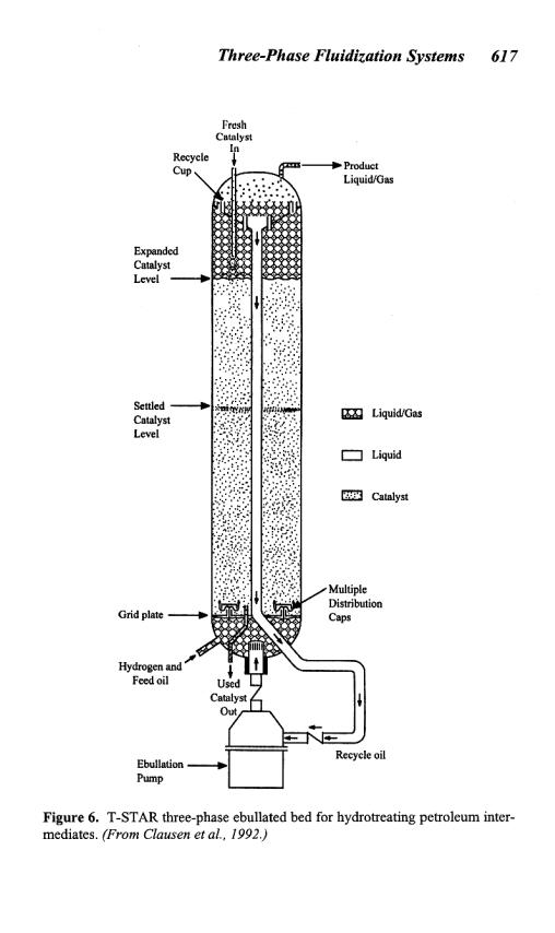
The T-STAR ebullated bed is shown schematically in Fig. 6. The figure demonstrates that a uniform catalyst distribution is maintained throughout the reaction chamber via the upward flow of the hydrogen, feed oil, and recycle oil. The internal recycle allows for increased conversion and assists in maintaining a uniform temperature throughout the reactor. Careful monitoring of the temperature in an ebullated bed
618 Fluidization, Solids Handling, and Processing
reactor is essential to prevent temperature runaway because of formation of stagnant regions or maldistribution of gas and liquid flows. The ease of on-stream catalyst replacement is also demonstrated. Since the presence of internals in an ebullated bed reactor lead to catalyst expansion in the annular region of the fluidized bed, the operation can be more precisely termed annular three-phase fluidization. In an air-water system at atmospheric conditions, the behavior of annular three-phase fluidized beds is different from the behavior of a “conventional” (no internals) three-phase fluidized bed with equal cross-sectional area. This altered behavior is due to the imposed physical constraints on the bed hydrodynamics, which are absent in a conventional fluidized bed of equal cross-sectional area (Fan et al., 1987a). Note, however, that a commercial ebullated bed reactor is designed with a small inner column to outer column diameter ratio and that hydrogen-hydrocarbon systems at industrial hydrotreating conditions have extremely high gas holdup with small dispersed bubbles; consequently, the physical constraints on the hydrodynamics caused by the presence of the inner column under these conditions can be negligibly small (Fan, 1989). Gas holdup (volume %) in the ebullated bed reactor can be as high as 0.50 (Tarmy et al., 1984) while the bubble size may be as small as 0.68 mm.
As described, ebullated or three-phase reactor technology has considerable flexibility in processing various feedstocks and in providing a range of products in the hydrotreating/hydrocracking of petroleum intermediates. In hydrotreating light cycle gas oil, ebullated bed technology was found to have several advantages over fixed bed hydrotreating including: smaller reactor requirement, lower hydrogen consumption, lower pressure operation, and a lower utility cost (Johns et al., 1993). The ability to continuously replace catalyst, remove large amounts of heat, and operate continuously without any quenching steps allows the ebullated bed to produce a diesel fuel that meets the EPA mandated restrictions on sulfur content. A pilot scale reactor system developed by Texaco implemented the ebullated bed technology for a six month period with constant catalyst activity maintained, and no operational problems were reported (Johns et al., 1993).
In normal operation of ebullated bed reactors, the reactor feed temperature is the control variable. The desired reactor feed temperature depends on both the feed rate and feed composition. The feed temperature is chosen such that the overall heat generation in the reactor is used to elevate the low temperature feed material to the bed temperature during
Three-Phase Fluidization Systems 619
the adiabatic operation of the reactor. Additional temperature control can also be provided by immediately shutting off the hydrogen supply. Ideally the ebullated bed reactor operates without any internal nonuniformities; however, in practice such nonuniformities may occur. Adequate pressure drop across the distributor plate is needed to provide uniform gas and liquid distribution in the reactor. During steady state operation, the superficial gas velocity decreases axially because of hydrogen consumption, yet, for a given axial location, the velocity is nearly uniform with respect to radial and angular position. Other factors affecting the normal operation of ebullated bed reactors include process parameters associated with the internal recycle stream variabilities, such as liquid velocity, gas velocity, recycle cup design, and gas bubble and catalyst entrainment.
4.3Fischer-Tropsch Synthesis
One of the most important, and perhaps the best studied, applications of three-phase fluidization is for the hydrogenation of carbon monoxide by the Fischer-Tropsch (F-T) process in the liquid phase. In this process, synthesis gas of relatively low hydrogen to carbon monoxide ratio (0.6 ~ 0.7) is bubbled through a slurry of precipitated catalyst suspended in a heavy oil medium. The F-T synthesis forms saturated and unsaturated hydrocarbon compounds ranging from methane to high-melting paraffin waxes (MW > 20,000) via the following two-step reaction:
CO + 2H 2 → (-CH2 -) + H2 O |
Hr (227°C) = -165 kJ/mol |
CO + H2 O → H2 + CO2 |
Hr (227°C) = - 39.8kJ/mol |
The overall reaction of the desired hydrocarbon synthesis is thus
2 CO + H2 → (-CH2 -) + CO2 |
Hr(227°C) = - 204.8kJ/mol |
Selectivity to desired products including light hydrocarbons, gasoline, or diesel fuel depends upon the catalyst employed, the reactor temperature, and the type of process employed. Products of the F-T synthesis are suitable for further chemical processing because of their predominantly straight chain structure and the position of the double bond at the end of the chain. By-products formed on a lesser scale include alcohols, ketones, acids, esters, and aromatics.
620 Fluidization, Solids Handling, and Processing
The catalysts used in the F-T synthesis are produced from iron precipitation and are typically less than 50 μm in size. With the small size of the catalyst particles, the three-phase reacting system is commonly referred to as a slurry bubble column. The highly exothermic nature of the desired synthesis is the cause of two of the main technical problems associated with the F-T synthesis: that of removal of the heat of reaction, amounting to about 25% of the heat of combustion; and avoidance of local overheating of the catalyst, which favors methane formation and catalyst deactivation (Kolbel and Ralek, 1980). The use of a slurry bubble column reactor effectively eliminates these problems by virtue of its excellent heat transfer characteristics and temperature uniformity. Other advantages offered by the slurry bubble column over fixed beds or moving beds in the absence of liquid media include high catalyst efficiency; favorable catalyst regeneration conditions; flexibility in establishing operating conditions, which allows economical control of the synthesis; ease of addition or removal of catalyst; and simplicity of construction and, therefore, lower capital costs. One disadvantage of the slurry bubble column in this case is the degree of backmixing of the liquid and, to a lesser extent, the gas phase, which limits the conversion and specific product selectivity attainable. The backmixing problems, however, can be reduced by using baffles.
Transport properties and reaction engineering aspects of F-T synthesis have been the subject of comprehensive reviews, e.g., Kolbel and Ralek (1980), Anderson (1984), and Saxena et al. (1986). Readers are referred to these references for details on the F-T synthesis and the extensive literature listings contained in them.
One recent development in low-temperature F-T synthesis that requires mentioning is the development by Sasol of a commercial scale Slurry Phase Distillate process, which produces high quality fuels, solvents, paraffins, and waxes from hydrogen and carbon monoxide. The process is located in a plant in Sasolburg, South Africa and consists of a 4.8 m diameter slurry bed reactor capable of producing environmentally friendly diesel from natural gas, providing the opportunity to convert remote natural gas reserves into low aromatic content, sulfur-free diesel fuel that burns cleanly with low particulate emissions. Sasol believes the reactor technology and operational mode provides the capability for performing exothermic reactions in slurry phase catalytic systems beyond F- T synthesis (Inga, J. R., personal communication, 1994).
Three-Phase Fluidization Systems 621
Another current development in the use of F-T chemistry in a threephase slurry reactor is Exxon’s Advanced Gas Conversion or AGC-21 technology (Eidt et al., 1994; Everett et al., 1995). The slurry reactor is the second stage of a three-step process to convert natural gas into a highly paraffinic water-clear hydrocarbon liquid. The AGC-21 technology, as in the Sasol process, is being developed to utilize the large reserves of natural gas that are too remote for economical transportation via pipelines. The converted liquid from the three-step process, which is free of sulfur, nitrogen, nickel, vanadium, asphaltenes, polycyclic aromatics, and salt, can be shipped in conventional oil tankers and utilized by most refineries or petrochemical facilities.
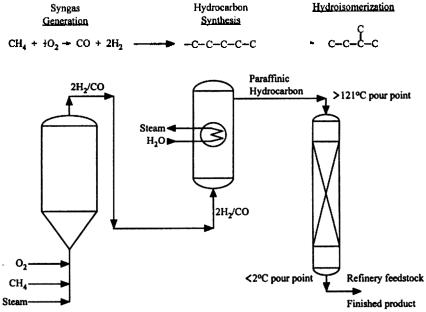
The three-step process for the AGC-21 technology is shown in Fig. 7. The three-phase slurry reactor contains an internal heat transfer coil to provide effective heat removal from the exothermic reaction. The feed to the hydrocarbon (F-T) synthesis step is a hydrogen/carbon monoxide synthesis gas (syngas) with 2/1 H2/CO ratio. The product from the slurry reactor is a high wax content material, which undergoes further upgrading in the third step. The catalyst is multimetallic, cobalt-based solid particles optimized for operation in a slurry environment (Eidt et al., 1994). Separations are required to recover the product from the catalyst containing slurry. Demonstration of the process has been conducted at Exxon Research and Development Laboratories in Baton Rouge, Louisiana (Everett et al., 1995) with a slurry reactor which was 1.2 m in diameter and approximately 21 m in height. The design and development target for the AGC-21 process are facilities capable of producing 8–16 km3/day of liquid hydrocarbon (Eidt et al., 1994).
4.4Methanol Synthesis
Synthesis gas can be reacted or reformed to make methanol through highly exothermic reactions:
CO + 2 H2 |
↔ CH3OH (l) |
Hr (255°C) = - 91.9 kJ/mol |
CO2 + 3 H2 |
↔ CH3 OH (l) + H2 O |
Hr (255°C) = -51.2kJ/mol |

Three-Phase Fluidization Systems 623
heat exchanger providing the necessary heat removal. The inherent temperature uniformity of three-phase systems increases catalyst life, insures optimum selectivity and reaction rate, and reduces NOX formation. The three-phase systems can be operated in a fluidized bed mode with catalyst particles between 3 and 6 mm in size or in a slurry bubble column mode with catalyst particles about 50 µm in size. Research efforts in catalyst activation procedures, choice of liquid medium, reactor hydrodynamics, and reactor modeling are currently being pursued for improving the process efficiency, design, and evaluations (e.g., Toseland et al., 1995).
Part II: Three-Phase Biofluidization
5.0BIOLOGICAL APPLICATIONS OF THREE-PHASE FLUIDIZATION
5.1Introduction
The many positive features of three-phase fluidization are readily apparent to biochemical engineers. Improved mass transfer, improved solid and liquid mixing, elimination of clogging, and other advantages of the technique as compared to packed bed and suspended cell bioreactors, detailed in Table 11, have been confirmed for a wide spectrum of biological processes, such as wastewater treatment, antibiotic production, and animal cell culture. By immobilizing cells on or in particles, washout of biomass is prevented even at relatively high flow rates, unlike the situation in continuous suspended cell reactors. Several limitations to the technique, listed in Table 12 exist; however, the favorable aspects of threephase biofluidization often outweigh the negatives and have encouraged development of many applications, especially in wastewater treatment. Numerous examples of full-scale three-phase fluidized wastewater treatment facilities exist (Fan, 1989). Industrial fermentation and cell culture applications have been somewhat slower to develop, but are becoming more and more common.