

Yang Fluidization, Solids Handling, and Processing
.pdfAttrition in Fluidized Beds and Pneumatic Conveying Lines 445
equation which yields a size distribution vector of the product (cf. British Materials Handling Board, 1987).
The use of selection and breakage functions is much more cumbersome than working with a single index number. This concept has, therefore, been used only for the description of comminution processes but not for the description of attrition.
3.2Attrition Rate
The assessment of attrition is mainly based on the examination of the behavior of a group of particles. In fluidization technology the total or overall attrition rate Ra,tot is commonly defined by the relative change of bed weight, Wbed, with time,
Eq. (2) |
Ra ,tot |
= − |
1 |
|
dWbed |
Wbed |
|
dt |
|||
|
|
|
|
or, alternatively by the relative change in elutriated fines, Wel, with time,
Eq. (3) |
Ra ,tot |
= |
1 |
|
dWel |
Wbed |
|
dt |
|||
|
|
|
|
Whether Eq. (2) or Eq. (3) is chosen will normally depend on the type of equipment used. When comparing different authors’ works, attention should be paid to the definition of Wbed. For batch processes it may either be the initial bed mass or the instantaneous inventory of the bed.
In fluidized bed experiments, most authors assume that all attrition products are elutriated. Consequently, they measure either the decrease in bed mass and use Eq. (2) (e.g., Kono, 1981; Kokkoris et al., 1991, 1995) or the elutriated mass (e.g., Seville et al., 1992, Werther and Xi, 1993). It should be noted that all these authors used a certain particle size as a threshold below which all particles are assigned to be attrition products provided that all initial particles are clearly larger. Breakage events, which lead to particle sizes above the threshold level are, therefore, not considered. The choice of this threshold is very arbitrary and differs between the various research groups.
Attrition in Fluidized Beds and Pneumatic Conveying Lines 447
methods to assess the material grindability, i.e., the Hardgrove Index and the Bond or Work Index. Both apply very large forces that cause far greater breakage than in usual fluidized bed processes, pneumatic conveying, or friability tests. Nevertheless, they may serve as a guide to the friability of some materials. For example, Sishtla et al. (1989) observed an nterdependence between the Hardgrove Index and the attrition tendency of different types of char in a fluidized bed.
The Hardgrove Index is based on the quantity of new surface produced during a specific grinding process on a sample of material of a welldefined size range (595 to 1190 microns). For the practical use it is defined in ASTM D409-71. The Bond or Work Index represents the energy required in a ball mill to reduce one short ton of material from a theoretically infinitely larger particle size to a size range at which 80% of its weight is smaller than 100 µm. It is described in detail by Bond (1961).
4.0ATTRITION TESTS
The large number of experiments that are termed attrition tests can be divided into two major fields of application, namely tests of material friability and experiments to study attrition phenomena. They will be separately discussed in the following subsections. The various test devices will be discussed afterwards.
4.1Friability Tests
In friability tests the material’s susceptibility to attrition is evaluated. But it is not as simple as it may seem at first to select the suitable test procedure. In this context Pell (1990) gave a simple thought experiment to illustrate the difficulties: If we took a batch of rubber stoppers and a batch of diamonds, and rubbed them on abrasive paper, we would conclude that the diamonds were more attrition resistant. If we instead struck the particles with a hammer we would conclude that the rubber were more attrition resistant. So, different test methods can rank materials differently with respect to their attritability. This effect was for example observed by Knight and Bridgwater (1985). They subjected spray-dried powders to a compression test, a shear test and a test in a spiral classifier. They found that each test gave a different ranking of the materials. Obviously, there is no
448 Fluidization, Solids Handling, and Processing
universal procedure for the measurement of a material’s propensity to attrition. The attrition resistance is relative and depends on both the material and the stress. An ideal attrition test should, therefore, duplicate at least the controlling stress in the real process under consideration. This is the reason why, for example, fluidized bed catalysts are normally tested in especially designed fluidized bed test facilities.
Friability tests can be used for various purposes. They are widely used in quality control. Here, samples of produced material are subjected to a more or less arbitrary but well defined stress. The attrition extent is assessed by comparison with a standard value and a decision is reached whether the material meets the standard. Moreover, friability tests are often used for comparison of different materials to select the most attritionresistant one. This is a usual procedure in the case of catalyst development. For example, Contractor et al. (1989) tested a new developed fluidized bed VPO-catalyst in a submerged-jet attrition test (described below). Furthermore, the specific attrition rate of a material in a certain process can be roughly estimated by friability tests. In this case the stress must be similar to that occurring in the process and the obtained degradation extent must be compared with those of other materials from which the process attrition rate is known.
Results that are obtained by different friability tests are usually not comparable. All these tests give only a relative attrition resistance and numerical results are only useful in connection with detailed information about the test considered.
4.2Experiments to Study Attrition Mechanisms
Attrition cannot normally be directly investigated in the large-scale process. It is, for example, impossible to analyze the whole bulk of material and it is nearly impossible or at least very expensive to vary parameters in a running industrial process. For that reason, attrition has to be investigated in small-scale experiments. The results of these experiments require a model or at least an idea of the governing attrition mechanisms to be applied to the large-scale process. In principle, there are two different “philosophies” of attrition modeling.
The most commonly used philosophy is to design a test facility that simulates the relevant process stress. Examples of such test facilities are the various jet attrition test devices which are used in fluidization technology.
Attrition in Fluidized Beds and Pneumatic Conveying Lines 449
The results can either be directly extrapolated to a large-scale process or reveal relationships which may serve as guidelines in the design of this process. It should be noted that most of these tests are batch tests, but most full-scale processes are continuous. So, the transfer of the results can be difficult due to the time dependence of the degradation.
In the second attrition-modeling philosophy (e.g., Yuregir et al., 1987) it is believed that the mechanics of particle interaction in process test devices and in the large-scale processes are not sufficiently understood to maintain the necessary dynamic similarity. Instead, test devices have to be used where the material is subjected to a well-defined stress like compression, impact or shear. The chosen test should preferably apply the type of stress that is considered as the main source of attrition in the respective large-scale process. The complete process attrition can than be described by coupling of the test results with a model which describes the motion of fluid and particles and with it the frequency and extent of the stress. Ghadiri et al. (1992b, 1994, 1995) have applied this concept to jet attrition in the fluidized beds. Salman et al. (1992) used this approach to describe attrition in dilute pneumatic conveying lines.
4.3Test Equipment and Procedures
Detailed reviews of such test procedures are given by Bemrose and Bridgwater (1987) and the British Material Handling Board (1987). The present subsection is restricted to a short discussion of those tests that are relevant for fluidized beds or pneumatic conveying lines.
Fluidized Bed Tests. These tests have direct relevance to all applications where particles are subjected to conditions of fluidization. Some authors believe that these tests can also to some extent simulate the stress of pneumatic transport. Coppinger et al. (1992) found at least a good correlation with the attrition resistance in dense-phase pneumatic conveying when they tested various powders in a slugging fluidized bed.
Most fluidized bed tests are currently carried out as so-called sub- merged-jet tests, where high-velocity gas jets submerged into a fluidized bed produce high attrition rates in a well-defined short period of time. The majority of these tests are based on the device suggested by Forsythe and Hertwig (1949). The setup consists of a 0.0254 m ID and 1.52 m long glass pipe, which bears a canvas filter at its upper end and is sealed by an orifice plate at the bottom. This latter plate contains a single 0.4 mm ID (1/64”)
450 Fluidization, Solids Handling, and Processing
orifice in its center. The apparatus is operated in such a way that the jet gas velocity approaches the speed of sound in the orifice. The filter keeps all material inside the system. In order to assess the degradation extent, it is suggested to screen the material by wet sieving through -325 mesh (44 µm). The attrition rate is defined as the ratio of the increase in weight percent of -325 mesh particles and the weight percent of +325 mesh particles in the initial material. Using this test procedure, one has to take into account that the attrition-produced fines that are kept in the system might affect the material’s attritability. Moreover, there are difficulties in using this test as a friability test, because the results are time integrated and have to be assessed with help of the particle size distribution. The materials which are to be compared should, therefore, have a similar initial particle size distribution and an identical pretreatment.
These difficulties are avoided in Gwyn’s (1969) design (Fig. 3). Here, the attrition products are not kept inside the system but it is rather assumed that they are elutriated. In the enlarged diameter top section, gravity separation defines the limiting diameter of the elutriable particles. The attrition rate is assumed to be given by the elutriation rate. The steadystate elutriation rate can, therefore, be used as a friability index.
It should be noted here that the quantitative results obtained in a Gwyn-type attrition apparatus will in general depend not only on the cut size of the gravity separator but also on the particle size distribution of the particulate material tested. If the gas mass flow and the temperature are kept constant, then a variation in the solids density will result in a shift of the cut size and thus in the amount of material collected as “attrition product.” Another point concerns the particle size distribution of the bed material. If the original solid sample is prepared by, for instance, sieving or sifting such that the smallest size is significantly larger than the cut size of the gravity separator, then one can be fairly sure that the elutriated material is indeed due to attrition. On the other hand, if the original particle size distribution contains a lot of fines, i.e., the cut size of the gravity separator is located somewhere inside the original particle size distribution, then the steady state of the attrition test will inevitably yield in the elutriated material not only attrited debris but also mother particles which have shrunk, due to attrition, to a size below the cut size. It is clear that in this latter case the attrition rate will differ from the one obtained with the previous test.

Attrition in Fluidized Beds and Pneumatic Conveying Lines 451
Figure 3. Schematic drawing of the fluidized bed test facility suggested by Gwyn (1969).
Both devices described above were developed in order to test the friability of fluid-cracking catalysts. Nowadays the application of these or similar tests is a common procedure in the development of fluidized bed catalysts. Contractor et al. (1989), for example, used a submerged-jet test to compare the attrition resistance of newly developed VPO catalysts. In fact, such tests can be applied to any type of fluidized bed processes. Sometimes they have to be slightly modified to adapt them to the process under consideration. The drilled plate may, for example, be substituted by
452 Fluidization, Solids Handling, and Processing
a porous plate if only attrition in the bed is of interest. Even temperature and pressure can be adapted. Vaux et al. (1981) investigated, for example, the friability of limestone sorbent that is used for fluidized bed combustion. By surrounding a “Gwyn-type” test facility with a heating system, they took thermal shock and calcination into account.
Pneumatic Conveying Tests. In contrast to fluidized bed tests, no standard equipment exists that simulates the stress on particles in pneumatic conveying lines. There is no friability test quoted in the pertinent literature that is based on a specific pneumatic conveying system.
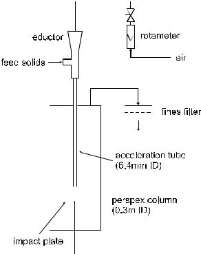
Tests Applying Well-Defined Stress. As mentioned in Sec. 2, one can distinguish three pure and well-defined mechanical stresses on bulk solids material, namely compression, impact and shear. There are numerous tests that are based on compression and shear, e.g., Paramanathan and Bridgwater (1983), Neil and Bridgwater et al. (1994), Shipway and Hutchings (1993), but they are not further discussed in this chapter because these stresses are usually not relevant with respect to fluidized beds and pneumatic conveying lines. On the other hand, impact stress very often occurs whenever particles hit walls or other particles. Attrition caused by impacts can be observed, for instance, in grid jets, cyclones and bends or due to free fall. Consequently there is a great variety of impact tests that try to simulate these particular stresses. There are, for example, various drop shatter tests where the material falls under gravity onto a hard surface or a fixed bed. Such a test was carried out by Zenz and Kelleher (1980), who considered catalyst attrition due to free fall in a CFB downcomer. There are also standardized forms for coal and coke, respectively (ASTM D 3038). However, the probably most relevant impact tests are those where pneumatically accelerated particles are impacted onto a target. Yuregir et al. (1986, 1987) pioneered this type of test in their work on NaCl salt. Up to now such test devices have found a broad industrial application as friability tests. For example, Fig. 4 shows the set-up used by PSRI (Knowlton, 1996). It requires about 50 to 100 grams of material to conduct a test. The velocity at which the solids strike the impact plate is approximately 85 m/s. Higher velocities can be used, but the materials will completely shatter at velocities greater than a velocity called the threshold velocity. This is for most materials greater than 85 m/s. If velocities above the threshold velocity are used, then no relative attritability information can be obtained. The great advantage of such an impact test is that it can be used for a wide range of materials (from Geldart’s Group C to Group D).
Attrition in Fluidized Beds and Pneumatic Conveying Lines 453
Figure 4. Schematic drawing of the impact test facility used by PSRI. (Knowlton, 1996.)
Other Tests. The so-called “tumbler tests” are usually used for testing material like coke, coal, iron ore pellets or tablets. They can be divided into drum tests and ball mill type tests. The latter type is used to derive both the Hardgrove Index and the Bond’s Work Index, which are often used to classify the material friability as described in Sec. 3. They are generally more suited to coarse material. The Hardgrove Grindability test requires an initial size range form 595 to 1190 microns.
The Grace-Davison jet-cup attrition test is often used to test the friability of catalysts (e.g., Weeks and Dumbill, 1990; Dessalces et al., 1994). The respective jet-cup apparatus is sketched in Fig. 5. The catalyst sample is confined to a small cup, into which air is tangentially added at a high velocity (about 150 m/s). Some authors (e.g., Dessalces et al., 1994)
