

12 2 Background
Definition 2.4. A computation graph G is computable i there is at least one node of type delay contained within the loop body of each loop in G.
2.4 The Multiple Word-Length Paradigm
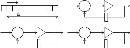
Throughout this book, we will make use of a number representation known as the multiple word-length paradigm [CCL01b]. The multiple word-length paradigm can best be introduced by comparison to more traditional fixedpoint and floating-point implementations. DSP processors often use fixedpoint number representations, as this leads to area and power e cient implementations, often as well as higher throughput than the floating-point alternative [IO96]. Each two’s complement signal j S in a multiple word-length implementation of computation graph G(V, S), has two parameters nj and pj , as illustrated in Fig. 2.4(a). The parameter nj represents the number of bits in the representation of the signal (excluding the sign bit), and the parameter pj represents the displacement of the binary point from the LSB side of the sign bit towards the least-significant bit (LSB). Note that there are no restrictions on pj ; the binary point could lie outside the number representation, i.e. pj < 0 or pj > nj .
|
p |
|
(n,v(t)) |
|
|
|
|
|
(n,w(t)) |
(n,x(t)) |
|
S |
... |
|
|
+ |
|
|
|
|
|
|
|
|
|
|
|
(n,z(t)) |
(n,y(t)) |
|
n |
|
|
(c) |
|
|
(a) |
|
|
|
|
|
|
|
|
|
|
(a,v) |
(b,w) |
(c,x) |
(n,0) |
(n,0) |
(n,0) |
|
+ |
|
|
+ |
|
|
(e,z) |
(d,y) |
|
(n,0) |
(n,0) |
|
(b) |
|
|
(d) |
|
Fig. 2.4. The Multiple Word-Length Paradigm: (a) signal parameters (‘s’ indicates sign bit), (b) fixed-point, (c) floating-point, (d) multiple word-length
A simple fixed-point implementation is illustrated in Fig. 2.4(b). Each signal j in this block diagram representing a recursive DSP data-flow, is annotated with a tuple (nj , pj ) showing the word-length nj and scaling pj of the signal. In this implementation, all signals have the same word-length and scaling, although shift operations are often incorporated in fixed-point designs, in order to provide an element of scaling control [KKS98]. Fig. 2.4(c) shows a standard floating-point implementation, where the scaling of each signal is a function of time.
2.5 Summary |
13 |
A single uniform system word-length is common to both the traditional implementation styles. This is a result of historical implementation on single, or multiple, pre-designed fixed-point arithmetic units. Custom parallel hardware implementations can allow this restriction to be overcome for two reasons. Firstly, by allowing the parallelization of the algorithm so that di erent operations can be performed in physically distinct computational units. Secondly, by allowing the customization (and re-customization in FPGAs) of these computational units, and the shaping of the datapath precision to the requirements of the algorithm. Together these freedoms point towards an alternative implementation style shown in Fig. 2.4(d). This multiple wordlength implementation style inherits the speed, area, and power advantages of traditional fixed-point implementations, since the computation is fixed-point with respect to each individual computational unit. However, by potentially allowing each signal in the original specification to be encoded by binary words with di erent scaling and word-length, the degrees of freedom in design are significantly increased.
An annotated computation graph G (V, S, A), defined in Definition 2.5, is used to represent the multiple word-length implementation of a computation graph G(V, S).
Definition 2.5. An annotated computation graph G (V, S, A), is a formal representation of the fixed-point implementation of computation graph G(V, S). A is a pair (n, p) of vectors n N|S|, p Z|S|, each with elements in one-to- one correspondence with the elements of S. Thus for each j S, it is possible to refer to the corresponding nj and pj .
2.5 Summary
This chapter has introduced the basic elements in our approach. It has described the FPGAs used in our implementation, explained the desciption of signals using the z-transform, and the representation of algorithms using computation graphs. It has also provided an overview of the multiple word-length paradigm, which forms the basis of our design techniques described in the remaining chapters.
This page intentionally left blank