

104 5 Saturation Arithmetic
5.6 Results and Discussion
Algorithm CompOptAlg has been implemented in MATLAB [MAT] in order to leverage its numerical integration routines, at the cost of increased execution time over an extension to the C implementation used in Chapter 4. However all execution runs discussed in this section are completed within 10 minutes on a Pentium III 450MHz, compared to 4 minutes for a Matlab implementation of Algorithm Word-LengthFalling and 10 seconds for calculation of the optimum uniform word-length. In addition, the execution time of Algorithm CombOptAlg will grow at the same rate as that of Algorithm Word-LengthFalling.
To illustrate the applicability of saturation arithmetic optimization to different types of design, two 4th order IIR filers are generated. One is a narrow bandpass elliptic filter, and one is a lowpass elliptic filter. Both filters are to be driven with a speech input [FRE93]. Clearly the narrow bandpass filter will have very high theoretical peak values at internal signals, as would be determined by 1 scaling. However an input signal that would cause internal signals to reach these peaks is unlikely to be present in a speech signal, which contains a wide range of frequency components. Thus the ratio between 1 peak value at any signal and the peak value reached during a simulation run is likely to be relatively large. In contrast the equivalent ratios in the lowpass filter are likely to be much more modest.
Fig. 5.15 shows an execution trace of Algorithm CombOptAlg executing on the bandpass filter, illustrating the change in system area and error variance as the algorithm refines the solution. Two plots are superimposed in the error variance trace: these are the error due to truncation alone, and the overall error. It is clear that until iteration 42, the contribution of saturation to the overall error is negligible. At this iteration the decision is made to reduce a binary point location of one of the signals, resulting in a significant saturation error. However by the end of the optimization run it is clear that the truncation error yet again dominates the saturation error.
5.6.1 Area Results
The standard approach of using simulation to determine signal scaling aims to avoid overflow for the specific input sequences provided, though not necessarily for all input sequences. The scaling of each signal through the use of simulation, and hence the area of a simulation-scaled system, therefore depends on the length of input sequence used for simulation. The longer the input sequence, the more the ‘tails’ of the pdf of an internal signal are likely to be encountered. Simulating the system on a short input sequence may result in a smaller area at the cost of a larger saturation error on unencountered input sequences, when compared to lengthy simulation runs.
In contrast, Algorithm CombOptAlg tolerates overflow errors if these errors help to achieve a small implementation cost, and is able to estimate the

5.6 Results and Discussion |
105 |
|
3000 |
|
|
|
|
|
|
|
cells |
2500 |
|
|
|
|
|
|
|
logic |
|
|
|
|
|
|
|
|
|
|
|
|
|
|
|
|
|
/ No. |
2000 |
|
|
|
|
|
|
|
|
|
|
|
|
|
|
|
|
estimate |
1500 |
|
|
|
|
|
|
|
1000 |
|
|
|
|
|
|
|
|
area |
|
|
|
|
|
|
|
|
|
|
|
|
|
|
|
|
|
|
500 |
20 |
40 |
60 |
80 |
100 |
120 |
140 |
|
0 |
|||||||
|
|
|
|
|
iteration |
|
|
|
|
10−5 |
|
|
|
|
|
|
|
estimate |
10−10 |
|
|
|
|
|
|
|
|
|
|
|
|
|
|
|
|
variance |
10−15 |
|
|
|
|
|
|
|
|
|
|
|
|
|
|
|
|
error |
10−20 |
|
|
|
|
|
|
|
|
|
|
|
|
|
|
|
|
|
10−25 |
20 |
40 |
60 |
80 |
100 |
120 |
140 |
|
0 |
|||||||
|
|
|
|
|
iteration |
|
|
|
Fig. 5.15. An execution trace of Algorithm CombOptAlg executed on a 4th order narrow bandpass elliptic IIR filter
severity of such errors for the average input sequence. For this reason, it is to be expected that Algorithm CombOptAlg may generate systems of smaller overall area than those generated through a simulation-based scaling followed by Algorithm Word-LengthFalling for word-length optimization.
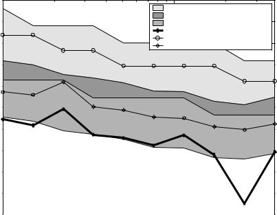
Fig. 5.16 shows a comparison of di erent approaches to area / error tradeo s for the bandpass filter example. Plots (e) and (f) correspond to the approach detailed in Section 4.4 based on 1 scaling followed by word-length optimization. Simulation-based scaling results are illustrated as regions (a) and (c): the upper curve in the region corresponds to simulation with a relatively long input sequence (105 samples at 8kHz, a spoken announcement), whereas the lower curve corresponds to simulation with a relatively short input sequence (3 · 103 samples at 8kHz, a spoken word). Region (a) illustrates a system that has been simulation-scaled, and with the optimum uniform word-length. Region (c) illustrates a system that has been simulation-scaled and then word-length optimized using Algorithm Word-LengthFalling. Region (b) illustrates the overlap between regions (a) and (c). Finally plot (d) corresponds to Algorithm CombOptAlg, a combined scaling and word-length optimization procedure.
106 5 Saturation Arithmetic
|
1200 |
|
|
|
(a) uniform / sim |
|
|
(b) uniform / sim − wl opt / sim overlap |
|
1150 |
(c) wl optimized / sim |
|
|
(d) comb optimized |
|
|
(e) uniform / l1 |
|
1100 |
(f) wl optimized / l1 |
|
1050 |
|
system area |
1000 |
|
950 |
|
|
resulting |
900 |
|
|
|
|
|
850 |
|
|
800 |
|
|
750 |
|
|
700 |
10−5 |
|
10−6 |
|
|
|
specified error variance |
Fig. 5.16. Comparison of di erent design approaches for trading-o system area and error, for a 4th order narrow bandpass elliptic IIR filter
There are several important pieces of information revealed by Fig. 5.16. It may seem somewhat surprising that the upper line of region (a) has a larger area than plot (e), since (e) represents worst case 1-scaled results. (Similarly comparing region (c) to plot (f)). However recall that there is an area overhead associated with saturation arithmetic, and when performing simulation-based scaling saturators must be introduced when a signal is converted from (n, p) to (n − k, p − k) (Section 5.2). For the 1 case, the essentially cost-free operation of inverse sign-extension (Section 4.1.1) will su ce. This overhead is su cient to make the simulation-scaled system larger than the equivalent 1-scaled system, when a long simulation run is used. The overhead appears to be a price worth paying when the short simulation run is used, however for alternative input sequences the saturation error may violate the user-specified error constraint. Plot (d) demonstrates that superior area results can be achieved through Algorithm CombOptAlg, approximately matching the best-case of region (c), but not limited to the specific small input sequence used. In summary, Algorithm CombOptAlg has resulted in average system area for Altera Flex10k between 10.6% and 21.8% less than the standard saturation arithmetic approach of using a single uniform word-length and simulation to de-
5.6 Results and Discussion |
107 |
termine signal scaling. In addition average area reductions of 0.3% to 13.3% have been achieved compared to simulation-scaling followed by application of Algorithm Word-LengthFalling. The area has been reduced by 18% on average compared to uniform word-length and 1 scaling, and 7.9% compared to 1 scaling followed by application of Algorithm Word-LengthFalling. These data are summarized in Table 5.1.
Table 5.1. Average percentage improvement of Algorithm CombOptAlg over alternative approaches for a 4th order narrow bandpass elliptic IIR filter
|
simulation scaling |
1 scaling |
|
|
short input sequence |
long input sequence |
|
uniform word-length |
10.6% |
21.8% |
18.0% |
optimized word-length |
0.3% |
13.3% |
7.9% |
|
|
|
|
Fig. 5.17 shows the equivalent comparison for the lowpass filter example. In this case plot (d) lies consistently beneath region (a) and plot (e) lies consistently beneath region (b), illustrating that the saturation arithmetic area overhead is very significant for this example. Indeed, high quality solutions can be obtained through the procedure described in Section 4.4 alone, without the need for saturation arithmetic. Plot (c), representing Algorithm CombOptAlg performs consistently well, matching Algorithm Word-LengthFalling in most cases and improving upon it in other cases. Thus by judicious placement of saturators, it is even possible to use saturation arithmetic to improve the area consumption of this example. In summary, Algorithm CombOptAlg has resulted in average system area between 12.2% and 20.0% less than the standard saturation arithmetic approach of using a single uniform word-length and simulation to determine signal scaling. In addition average reductions of 5.7% to 13.0% have been achieved compared to simulation-scaling followed by application of Algorithm Word-LengthFalling. The area has been reduced by 11% on average compared to uniform word-length and 1 scaling, and 0.3% compared to 1 scaling followed by application of Algorithm Word-LengthFalling. These data are summarized in Table 5.2.
Table 5.2. Average percentage improvement of Algorithm CombOptAlg over alternative approaches for a 4th order lowpass elliptic IIR filter
|
simulation scaling |
1 scaling |
|
|
short input sequence |
long input sequence |
|
|
|
|
|
uniform word-length |
12.2% |
20.0% |
11.0% |
optimized word-length |
5.7% |
13.0% |
0.3% |
|
|
|
|
Area results have thus far been illustrated for fixed system function, while varying the specification on maximum error variance. It has been demon-