- •AMBA
- •Contents
- •List of Tables
- •List of Figures
- •Preface
- •About this document
- •Intended audience
- •Using this specification
- •Conventions
- •Typographical
- •Timing diagrams
- •Signals
- •Further reading
- •ARM publications
- •Feedback
- •Feedback on this product
- •Feedback on this specification
- •Introduction
- •1.1 About the AXI protocol
- •1.2 Architecture
- •1.2.1 Channel definition
- •Read and write address channels
- •Read data channel
- •Write data channel
- •Write response channel
- •1.2.2 Interface and interconnect
- •1.2.3 Register slices
- •1.3 Basic transactions
- •1.3.1 Read burst example
- •1.3.2 Overlapping read burst example
- •1.3.3 Write burst example
- •1.3.4 Transaction ordering
- •1.4 Additional features
- •Signal Descriptions
- •2.1 Global signals
- •2.2 Write address channel signals
- •2.3 Write data channel signals
- •2.4 Write response channel signals
- •2.5 Read address channel signals
- •2.6 Read data channel signals
- •Channel Handshake
- •3.1 Handshake process
- •3.1.1 Write address channel
- •3.1.2 Write data channel
- •3.1.3 Write response channel
- •3.1.4 Read address channel
- •3.1.5 Read data channel
- •3.2 Relationships between the channels
- •3.3 Dependencies between channel handshake signals
- •Addressing Options
- •4.1 About addressing options
- •4.2 Burst length
- •4.3 Burst size
- •4.4 Burst type
- •4.4.1 Fixed burst
- •4.4.2 Incrementing burst
- •4.4.3 Wrapping burst
- •4.5 Burst address
- •Additional Control Information
- •5.1 Cache support
- •5.2 Protection unit support
- •Atomic Accesses
- •6.1 About atomic accesses
- •6.2 Exclusive access
- •6.2.1 Exclusive access process
- •6.2.2 Exclusive access from the perspective of the master
- •6.2.3 Exclusive access from the perspective of the slave
- •6.2.4 Exclusive access restrictions
- •6.2.5 Slaves that do not support exclusive access
- •6.3 Locked access
- •Response Signaling
- •7.1 About response signaling
- •7.2 Response types
- •7.2.1 Normal access success
- •7.2.2 Exclusive access
- •7.2.3 Slave error
- •7.2.4 Decode error
- •Ordering Model
- •8.1 About the ordering model
- •8.2 Transfer ID fields
- •8.3 Read ordering
- •8.4 Normal write ordering
- •8.5 Write data interleaving
- •8.6 Read and write interaction
- •8.7 Interconnect use of ID fields
- •8.8 Recommended width of ID fields
- •Data Buses
- •9.1 About the data buses
- •9.2 Write strobes
- •9.3 Narrow transfers
- •9.4 Byte invariance
- •Unaligned Transfers
- •10.1 About unaligned transfers
- •10.2 Examples
- •Clock and Reset
- •11.1 Clock and reset requirements
- •11.1.1 Clock
- •11.1.2 Reset
- •Low-power Interface
- •12.2.4 Clock control sequence summary
- •Index

Clock and Reset
11.1Clock and reset requirements
This section gives the requirements for implementing the ACLK and ARESETn signals.
11.1.1Clock
Each AXI component uses a single clock signal, ACLK. All input signals are sampled on the rising edge of ACLK. All output signal changes must occur after the rising edge of ACLK.
There must be no combinatorial paths between input and output signals on both master and slave interfaces.
11.1.2Reset
The AXI protocol includes a single active LOW reset signal, ARESETn. The reset signal can be asserted asynchronously, but deassertion must be synchronous after the rising edge of ACLK.
During reset the following interface requirements apply:
•a master interface must drive ARVALID, AWVALID, and WVALID LOW
•a slave interface must drive RVALID and BVALID LOW.
All other signals can be driven to any value.
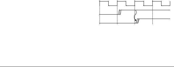
A master interface must begin driving ARVALID, AWVALID, or WVALID HIGH only at a rising ACLK edge after ARESETn is HIGH. Figure 11-1 shows the first point after reset that ARVALID, AWVALID, or WVALID, can be driven HIGH.
ARESETn
VALID
Figure 11-1 Exit from reset
11-2 |
Copyright © 2003, 2004 ARM Limited. All rights reserved. |
ARM IHI 0022B |
