

The Microcontroller Idea Book (Jan Axelson, 1994)
.pdfPowering Up
PORT 1 Bit Values:
Bit 0 = 1
Bit 1 = 1
Bit 2 = 1
Bit 3 = 1
Bit 4 = 1
Bit 5 = 1
Bit 6 = 1
Bit 7 = 1
If a port pin is open, or unconnected, its internal pull-up resistor will cause it to read as 1. If you connect a jumper wire from a port pin to ground, or bring the pin low by driving it with a logic low output, it should read 0. Line 10 in Listing 3-1 brings all of Port 1’s bits high, which enables them to be used as inputs.
Writing to Port 1
You can control the bits of Port 1 by writing to them. Listing 3-2 allows you to set or clear individual bits. Here’s an example of what happens when you run the program:
Enter a bit to set or clear (0-2, 4-7) :7
Enter 1 to set, 0 to clear :0
Enter a bit to set or clear (0-2, 4-7) :3
Do not change bit 3!
The program doesn’t allow you to change bit 3 (P1.3), because the 8052-BASIC circuit requires this bit to be high when accessing external memory (assuming that you’ve included U3B in your circuit). If you do clear bit 3 accidentally, you’ll crash the system and will have to reboot.
Listing 3-1. Displays the value of each bit in Port 1.
10 PORT1 = 0FFH
20 PRINT “PORT 1 Bit Values:”
30 PRINT “Bit 0 = ”,(PORT1.AND.1)
40 PRINT “Bit 1 = ”,(PORT1.AND.2)/2
50 PRINT “Bit 2 = ”,(PORT1.AND.4)/4
60 PRINT “Bit 3 = ”,(PORT1.AND.8)/8
70 PRINT “Bit 4 = ”,(PORT1.AND.10H)/10H
80 PRINT “Bit 5 = ”,(PORT1.AND.20H)/20H
90 PRINT “Bit 6 = ”,(PORT1.AND.40H)/40H
100 PRINT “Bit 7 = ”,(PORT1.AND.80H)/80H
110 END
The Microcontroller Idea Book |
41 |

Chapter 3
Listing 3-2. Allows you to set or clear individual bits of Port 1.
10 INPUT “Enter a bit to set or clear (0-2, 4-7) :”,X 20 IF X=3 THEN PRINT “Do not change bit 3!” : GOTO 10 30 INPUT “Enter 1 to set, 0 to clear :”,Y
40 IF Y=1 THEN PORT1=PORT1.OR.2**X
50 IF Y=0 THEN PORT1=PORT1.AND.0FFH-2**X
60 END
Run the program and follow the on-screen instructions to set or clear a bit. To monitor a port bit as you set and clear it, you can use a logic probe, voltmeter, or oscilloscope. For example, to monitor bit 0, place a logic probe on pin 1 of U1, or connect the + lead of a voltmeter to pin 1 and the - lead to ground.
Accessing Memory
Listing 3-3 allows you to read and write to external RAM. Here is an example of what happens when you run this program:
Enter 0 (read), 1 (write), or 2 (quit): 1 Free memory ranges from 397H to 1FFFH Enter an address to write to : 1000H Enter data to be written : 55H
55H has been written to address 1000H Enter 0 (read), 1 (write), or 2 (quit): 0 External RAM ranges from 0 to 1FFFH
Enter an address to read : 1000H 55H is stored in address 1000H
If you write to an address outside the range specified as free memory, you will overwrite the RAM currently in use to store your program and run BASIC-52. If you do this accidentally, your system may crash and you’ll have to reset the system and re-enter the program.
If you prefer decimal numbers to hex notation, change each PH0 in the program to PRINT. (PH0. includes a period; PRINT does not.)
Real-time Clock
Listing 3-4 demonstrates BASIC-52’s real-time clock by displaying an on-screen 60-second timer.
42 |
The Microcontroller Idea Book |
|
Powering Up |
|
|
Listing 3-3. Allows user to read and write to external memory. |
|
10 |
DO |
20 |
INPUT “Enter 0 (read), 1 (write), or 2 (quit): ”,RW |
30 |
IF RW=0 THEN GOSUB 70 |
40 |
IF RW=1 THEN GOSUB 120 |
50 |
WHILE RW<>2 |
60 |
END |
70 |
PH0."External RAM ranges from 0 to “,MTOP |
80 |
INPUT “Enter an address to read : ”,A |
90 |
B=XBY(A) |
100 |
PH0.B," is stored in address “,A |
110 |
RETURN |
120 |
PH0."Free memory ranges from “,LEN+512,” to “,MTOP |
130 |
INPUT “Enter an address to write to :”,A |
140 |
INPUT “Enter data to be written :”,B |
150 |
XBY(A)=B |
160 |
PH0.B," has been written to address “,A |
170 |
RETURN |
|
|
For the timer to be accurate, you must set XTAL to match the timing crystal your system uses.
Further Experiments
Feel free to continue experimenting with BASIC-52 programs, using the programming reference as a guide. You can do quite a bit with just these circuits.
Listing 3-4. Real-time clock.
10 |
CLOCK 1:TIME=0:SEC=0 |
20 |
DO |
30 |
ONTIME 1,60 |
40 |
WHILE SEC<60 |
50 |
END |
60 |
TIME=TIME-1 |
70 |
SEC=SEC+1 |
80 |
PRINT SEC |
90 |
RETI |
The Microcontroller Idea Book |
43 |

Chapter 3
Listing 3-5. This program uses BASIC-52’s GET instruction to detect when the user has pressed a key.
10 |
CLOCK1:TIME=0:SEC=0 |
20 |
PRINT “Press any key to quit” |
30 |
DO |
40 |
ONTIME 1,100 |
50 |
G=GET |
60 |
UNTIL G<>0 |
70 |
END |
100 |
TIME=TIME-1 |
110 |
PH0. PORT1 |
120 |
RETI |
Exiting Programs
Some programs, such as Listing 3-3’s, continue to run until the user requests to end it. In BASIC-52, there are several ways to detect that the user wants to stop a program.
Set a User Variable
In Listing 3-3, the program displays a menu of choices on the host computer’s screen. The program continues to run until the user selects QUIT by entering 2, which sets the variable RW to 2 and causes the DO...WHILE loop and the program to end.
Use GET
Sometimes, selecting a menu option isn’t convenient or appropriate. Listing 3-5 reads and displays the value of PORT1 once per second until the user presses any key at the host computer. The program uses BASIC-52’s GET operator to detect a keypress. GET stores the ASCII code of a keypress at the host computer. Setting a varialble equal to GET (line 50) causes GET to reset to 0. You can detect a keypress by reading GET periodically. If GET
Listing 3-6. This program will end only when the user presses CONTROL+C.
10 CLOCK 1:TIME=0:SEC=0
20 DO
30 ONTIME 1,100
40 WHILE 1=1
50 END
100 TIME=TIME-1
110 PH0. PORT1
120 RETI
44 |
The Microcontroller Idea Book |

Powering Up
Listing 3-7. This program ends when INT1 (pin 13) is brought low and causes an interrupt routine to execute.
10 |
CLOCK 1:TIME=0:SEC=0 |
20 |
A=0 |
30 |
PRINT “Bring INT1 (pin 13) low to end program.” |
40 |
DO |
50 |
ONTIME 1,100 |
60 |
ONEX1 200 |
70 |
WHILE A=0 |
80 |
END |
100 |
TIME=TIME-1 |
110 |
PHO. PORT1 |
120 |
RETI |
200 |
A=1 |
210 |
RETI |
doesn’t equal zero, it means that a key was pressed. In Listing 3-5, when GET no longer equals 0, the program ends.
Wait for CONTROL+C
You can always end a program by pressing CONTROL+C at the host’s keyboard. The only exceptions are runaway programs that have crashed the system and force you to reboot. Listing 3-6 is an expanded version of Listing 3-5. It continues to read and display PORT1 in an endless loop (DO...WHILE 1=1), until you press CONTROL+C.
Detect a Switch Press
A final method will end a program without any input from the host’s keyboard. You can use this in stand-alone projects that don’t connect to a host computer at all. Listing 3-7 ends when the 8052-BASIC’s pin 13 (INT1) goes low, which causes an interrupt routine to execute. Bring the pin low by jumpering it briefly to GND, or connect a pushbutton switch as described in Chapter 7.
The Microcontroller Idea Book |
45 |
46 |
The Microcontroller Idea Book |

Saving Programs
4
Saving Programs
In Chapter 3’s experiments, the BASIC-52 programs that you wrote were stored in RAM. This is fine for temporary use, but every time you power down, your program disappears and you have to start over.
This chapter shows you two ways to save BASIC-52 programs more permanently: by adding nonvolatile memory to the BASIC-52 system, and by downloading your programs to your host system’s disk. The nonvolatile memory may be battery-backed RAM, EEPROM, or EPROM. You can also use this memory for storing assembly-language programs or data that you want to save when you power down or reset. Disk storage is a convenient way to save programs if you want to edit them off-line, upload them to a different BASIC-52 system, or just save back-up copies.
Nonvolatile Memory Options
One of BASIC-52’s handiest features is its programming commands that store programs in nonvolatile (NV) memory: EPROM, EEPROM, or battery-backed RAM. The commands assume that the NV memory is addressed beginning at 8000h in external data memory.
With the addition of NV memory, you have two areas that may contain BASIC-52 programs: the NV memory, addressed beginning at 8000h, and the RAM, addressed beginning at 0. To distinguish between the two areas, you can call the memory beginning at 8000h the EPROM
The Microcontroller Idea Book |
47 |
Chapter 4
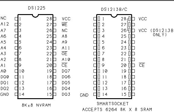
Figure 4-1. Pinouts for Dallas Semiconductor’s 8K NVRAM and SmartSocket.
space (even though it may contain NVRAM, EEPROM, or EPROM), and call the memory beginning at 0, up to 7FFFh or the top of RAM, the RAM space.
BASIC-52’s programming commands are designed to meet the requirements for EPROMs, using either of two programming algorithms, or procedures. You can use the same commands to store programs in NVRAM or EEPROM. Like EPROMs, these devices provide nonvolatile storage—in other words, their contents don’t disappear when power is removed. Plus, they have two advantages over EPROMs: they don’t need any special programming voltages, and they don’t need ultraviolet exposure to erase. This makes them much more convenient to use.
For these reasons, the first circuit we’ll look at offers a choice of NVRAM or EEPROM for nonvolatile storage. Later, we’ll add circuits that allow you to program EPROMs, for those who want this option.
NVRAM
Dallas Semiconductor offers NVRAM chips that you can use for nonvolatile storage. These work exactly like static RAM, except that they contain a lithium cell and backup circuits that retain the RAM’s contents when the main power supply is removed. The backup is
48 |
The Microcontroller Idea Book |

Saving Programs
guaranteed for at least ten years. Dallas also makes a product called the SmartSocket, which consists of an IC socket with an embedded lithium cell and backup circuits. To create a NVRAM, you plug your own static RAM chip into the SmartSocket.
Eight kilobytes is a convenient size that will store many short BASIC-52 programs, or fewer longer ones. For an 8K NVRAM, you can use a DS1225 NVRAM, or a DS1213B or DS1213C SmartSocket with a 6264 or similar static RAM. Figure 4-1 shows the pinouts.
The 1213B and 1213C SmartSockets differ only in that the 1213B will also accept a 24-pin 2K SRAM, with pins 1, 2, 27, and 28 unused, and the 1213C will also accept a 32K SRAM, which has address inputs at pins 1 and 26.
The DS1225 offers a choice of two write-protect voltages. On the -AB version, write protection is guaranteed when the power supply is less than 4.5V, and write operations are allowed when the power supply is greater than 4.75V. The SmartSockets use these same voltages. On the -AD and -Y versions of the DS1225, write protection is guaranteed when the supply is less than 4.25V, and write operations are allowed when the supply is greater than 4.5V. Either type should work in a BASIC-52 system with a regulated +5V supply. Access times of 250 nanoseconds or less are fine for the NVRAM.
Don’t be confused by the fact that Dallas describes its devices by the number of bits they store, rather than the number of bytes. For example, they call the 8-kilobyte DS1225 a 64K device.
You can order NVRAMs directly from Dallas Semiconductor (no minimum order), and from other vendors.
EEPROM
The other option for program storage is EEPROM. A typical EEPROM is guaranteed for 10,000 to 100,000 write cycles, compared to infinite write cycles for NVRAM. Access times for reading an EEPROM are similar to those for static RAM, but writing to EEPROM takes much longer. Most require 2 to 10 milliseconds after a write operation before you can access the chip again. In spite of the drawbacks, I’ve included EEPROM as an option because an 8K EEPROM may cost less than a comparable NVRAM.
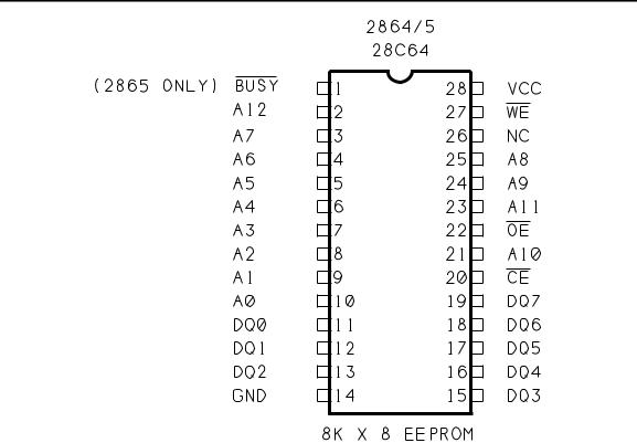
A typical part number for an 8K EEPROM is 2864 or 28C64. Figure 4-2 shows the pinout for a 28(C)64 EEPROM. Notice that its pinout, too, is very similar to that of a 6264 static RAM.
EEPROMs have two common ways of indicating that they are busy performing a write operation and are unable to be accessed. In one type, when the EPROM is busy, the data pins hold the last-written data, but with one or more bits inverted. BASIC-52’s programming
The Microcontroller Idea Book |
49 |
Chapter 4
Figure 4-2. Pinout for 8K EEPROM.
commands verify each byte after programming it, so the inverted data automatically keeps BASIC-52 from programming another byte until the EEPROM is ready to receive it.
Other EEPROMs have a busy output, usually at pin 1, which goes low when the EEPROM is busy. For this type, you can tie the busy output to pin 12 of U1. BASIC-52’s programming commands wait for a high logic level at this pin after programming each byte. Note that this means that pin 12 of the 8052-BASIC must be high (or not connected) during programming of any device. However, using the BUSY output is optional, since programming won’t continue until the programmed byte verifies.
Whether you choose EEPROM or NVRAM, be sure to ask for a data sheet for the device you buy, so you can verify its pinout, capacity, and timing characteristics.
Adding NVRAM or EEPROM
Figure 4-3 shows the added circuits for the NVRAM or EEPROM at U8. Because the circuits are an addition to Figure 3-1’s circuits, the parts continue the same numbering sequence, beginning with U8. AND gate U3C is the third gate of Figure 3-1’s U3. Table 4-1 is a parts list of the components needed to add Figure 4-3’s circuits to Figure 3-1.
50 |
The Microcontroller Idea Book |