Real-time processing with the Philips LPC ARM mcu using GCC and uCOS II RTOS (D.W. Hawkins, 2006)
.pdf
AR1803 |
May 10, 2006 |
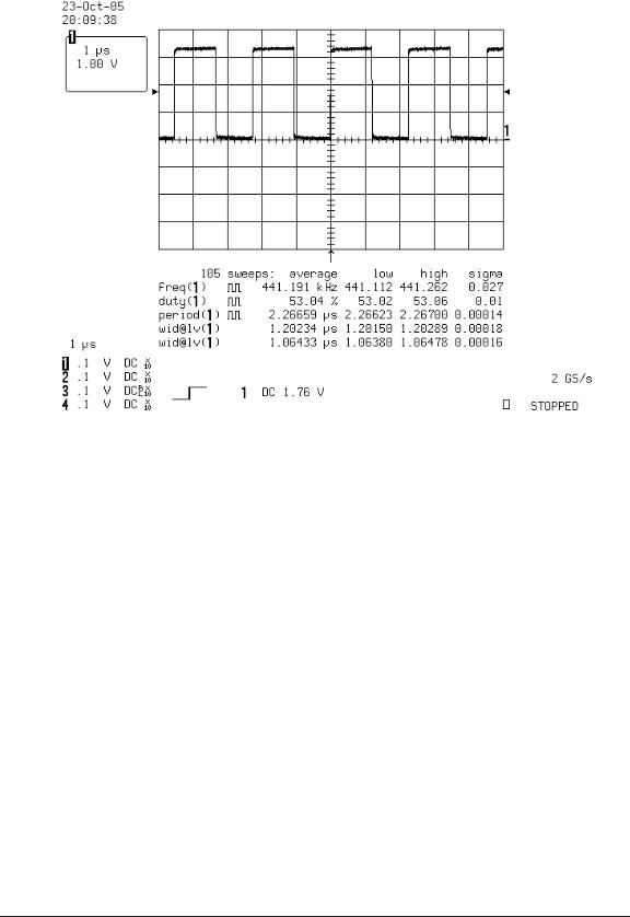
Figure 6: LPC2138 software generated FIQ context save/restore benchmarking. The Example 8(b) test application uses the vectored interrupt controller (VIC) to software generate an EINT1 interrupt. EINT1 is handled using an FIQ handler. The main application toggles the LED pins high, and the FIQ handler toggles the LED pins low. The high-time of the waveform is 1.20µs (72 clocks), while the low time is 1.06µs (64 clocks).
and make minimal use of the FIQ stack. Benchmarking of the uCOS-II RTOS is shown later. Example 8(a) used an external interrupt pin to test interrupt latency. The Vectored Interrupt
Controller in the LPC-series provides an alternative option for software testing of interrupts; the VIC software interrupt register, and software interrupt clear register (p49 [10]). Example 8(b) modifies Example 8(a) to use a software generated EINT1 interrupt. The main code still writes to the LEDs so that the code can be benchmarked using an oscilloscope, however, code is added to set and clear the software interrupt register (code to setup the external EINT1 interrupt is also removed). Figure 6 shows the waveform from the software generated FIQ interrupt. The high-time and low-time of the waveform are both slightly smaller than in Figure 5.
31

AR1803 |
May 10, 2006 |
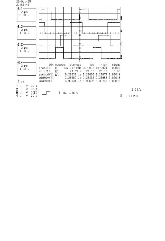
Figure 7: LPC2138 vectored IRQ prioritization. The Example 9(a) test application uses the vectored interrupt controller (VIC) to software generate EINT[0:3] interrupts which are enabled on the vectored IRQs 0 to 3. The main application toggles the LED pins 0 to 3 high, and the IRQ handlers each toggle one LED low. The figure shows how the EINT interrupts are serviced in order 0 to 3. The high-time of the EINT0 waveform is 1.34µs; similar to the previous tests. The high times of the other interrupts are progressively longer.
3.9Example 9: Multiple interrupts
This section benchmarks interrupt handling when dealing with multiple interrupt sources. The ARM core has two interrupt lines; the FIQ and IRQ. The FIQ is generally expected to have a single interrupt source, while the IRQ line can have multiple interrupt sources. The VIC on the LPC-series can be used to divide the IRQ sources into vectored (prioritized) IRQs, and non-vectored IRQs. For the vectored IRQs, the VIC acts like a hardware multiplexer, causing the processor to jump to the address of the handler of the highest priority interrupt. For the non-vectored IRQs, the same handler is provided, and the handler code has to perform the demultiplexing for multiple non-vectored sources.
Example 9(a) follows on from Example 8(b) and uses the VIC to setup four software interrupts on EINT[0:3]. The interrupts are set up to generate IRQ interrupts. The interrupt handlers are placed in IRQ vector slots VICVectAddr[0:3]. The main application sets LED[0:3] high, and each EINT handler sets a single LED low. Figure 7 shows the resulting LED waveforms.
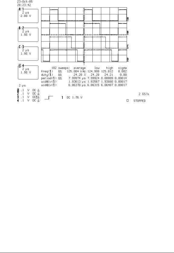
The VIC IRQ controller prioritizes when interrupts occur simultaneously. However, if an IRQ handler has already started, and a higher priority interrupt occurs, the higher priority handler will not run until after the current handler completes. Example 9(b) and Figure 8 demonstrate the problem. Example 9(b) starts by generating an interrupt on EINT3, and then EINT3’s IRQ handler is used to set EINT2’s LED high and generate an EINT2 interrupt. EINT2’s handler does the same for EINT1, EINT1’s handler does the same for EINT0, and EINT0 leaves it to main to restart the sequence. Its obvious from the figure that each lower priority interrupt is completing while a higher
32

AR1803 |
May 10, 2006 |
Figure 8: LPC2138 IRQ priority inversion. The Example 9(b) starts by generating a software interrupt on EINT3, and then each IRQ handler generates a software interrupt on the next higherpriority interrupt (except for EINT0, that handler leaves it to main to restart the process). Note how even though a higher priority interrupt has occurred, it does not get processed until the current handler completes.
priority interrupt is pending. The next section shows how interrupts can be made interruptible. Examples 6(a), 6(b), 9(a) and 9(b) used the GCC keyword interrupt to define interrupt handler
functions. Example 9(c) shows how interrupt handlers can be written without using the interrupt keyword. The example uses a short assembler coded sequence to save processor state, and then call a C-coded FIQ or IRQ handler. The C-coded IRQ handler reads from the VICVectAddr register to dispatch handler routines. Since those routines are called from a C function, they all need to be written as standard C-functions (without the interrupt keyword). The IRQ and FIQ exception vectors in the startup code were modified as follows;
_start: |
|
b reset |
/* reset */ |
b loop |
/* undefined instruction */ |
b loop |
/* software interrupt */ |
b loop |
/* prefetch abort */ |
b loop |
/* data abort */ |
nop |
/* reserved for the bootloader checksum */ |
ldr pc, irq_addr
/* FIQ ISR */ fiq_isr:
sub lr, lr, #4
stmfd sp!, {r0-r3, ip, lr} bl fiq_handler
33

AR1803 |
May 10, 2006 |
Figure 9: Example 9(c) waveforms. Example 9(c) uses assembler coded ISRs that then call C-coded functions. EINT0 is setup as a vectored IRQ, while EINT[1:3] are setup as non-vectored.
ldmfd sp!, {r0-r3, ip, pc}^
irq_addr: .word irq_isr irq_isr:
sub lr, lr, #4
stmfd sp!, {r0-r3, ip, lr} bl irq_handler
ldmfd sp!, {r0-r3, ip, pc}^
The FIQ vector service routine starts at its interrupt vector location, so the processor starts in the FIQ ISR when an FIQ interrupt occurs. The IRQ vector loads the program counter with the address of the IRQ assembler service routine, which is located just after the FIQ ISR. The FIQ ISR adjusts the link register address, saves it, along with the ARM Procedure Calling Standard (APCS) ‘scratch’ registers [3], to the stack, and calls the C-coded FIQ handler. When the handler returns, the FIQ IRQ performs a return-from-interrupt sequence. The IRQ ISR is similarly coded.
The reason for saving the APCS registers can be seen by disassembling the Example 9(c) code via arm-elf-objdump -d ex9c.elf. Looking at the code for irq_handler shows the prolog of that code saving several registers (not the ones saved by the ISR), and then the handler code uses r0-3. If the ISR code did not save these registers, then whatever was in those registers prior to the interrupt would be corrupted.
Figure 9 shows the waveforms from Example 9(c). The code is similar to Example 9(a), however, EINT0 is configured as a vectored IRQ, while EINT[1:3] are all configured as non-vectored. The example code provides details on how to setup the VIC. Comparison of Figure 7 to Figure 9 shows the increase in interrupt processing time caused by the implementation of Example 9(c).
34

AR1803 |
May 10, 2006 |
3.10Example 10: Interrupt nesting
The Philips LPC-series ARM microcontroller vectored interrupt controller (VIC) prioritizes interrupts under the condition of multiple interrupts occurring simultaneously, and it also prioritizes interrupts while interrupts are being serviced. When an interrupt occurs, the VIC modifies the interrupt enable state so that only higher-priority interrupts generate an IRQ to the processor core. This feature is not mentioned in the LPC2138 user manual (Chapter 5 [10]), but it is described in the ARM VIC PL190 documentation [2]. Without this feature, if IRQs were enabled to the core when a handler started, then any IRQ would interrupt the currently executing handler. The PL190 documentation also clarifies why you have to read from the VICVectAddr register, and then write to it once an interrupt has been serviced (p2-2 [2]);
Reading from the Vector Interrupt Address Register, VICVECTADDR, provides the address of the ISR, and updates the interrupt priority hardware that masks out the current, and any lower priority interrupt requests. Writing to the VICVECTADDR Register indicates to the interrupt priority hardware that the current interrupt is serviced, enabling lower priority or the same priority interrupts to be removed, and for the interrupts to become active to go active.
To allow interrupts of higher priority to interrupt an interrupt handler requires re-enabling IRQ interrupts to the processor core. The generation of an IRQ to the core while in IRQ mode will overwrite the IRQ mode saved program status register (SPSR_irq) and any return address currently in the link register (LR_irq). To avoid corrupting the IRQ mode state by re-enabling IRQ interrupts, a nested interrupt handler needs to change processor modes when enabling IRQ interrupts; ARM recommends changing to the system-mode (the privileged version of user-mode). Philips application note AN10381 [9] gives two examples of the implementation of interrupt nesting; a version implemented using assembler coded prolog and epilog code, containing a C-coded handler function, and a version implemented using a C-compiler generated interrupt handler containing inline-assembler code to perform the additional steps required to implement nesting.
Interrupt nesting can utilize an important feature provided by the VIC hardware prioritization logic; that reading the VICVectAddr register adjusts the interrupt enable mask to allow interrupts of higher-priority. This feature results in an alternative implementation of the nesting entry sequence demonstrated in AN10381, i.e., for a specific handler loaded into the VIC address registers, the entry sequence is (see the full list in Section 3.1 in reference [9])
1.Save IRQ context.
2.Clear the interrupt source.
3.Switch to system-mode and enable IRQ.
4.Save SYS context.
5. . . .
Since the handler function is executing as a consequence of the IRQ vector reading the VICVectorAddr register (via the statement ldr pc, [#-0xFF0] at the IRQ vector location), the currently executing IRQ priority has already been masked and can not generate another IRQ to the processor core. This means that the clearing of the interrupt source can be moved into the handler code. The consequence of that modification is that all handler prolog and epilog code is identical, so it can be replaced by a single assembler coded sequence, and all handler functions loaded into the VIC are simple C-functions. This improves the portability of the code, as compiler-specific interrupt handling keywords are no longer required.
35

AR1803 |
May 10, 2006 |
Nested interrupts can be implemented by having the IRQ vector jump to a routine that performs the following sequence;
1.Save IRQ context; by adjusting the link register, and saving the APCS registers (r0-3, ip), work registers r4-6, and the link register to the IRQ mode stack.
2.Save the IRQ mode SPSR into r4.
3.Read the handler address from the VICVectAddr register into r6 (causing the VIC to mask the current interrupt).
4.Write to the CPSR to switch to system mode with IRQ interrupts enabled.
5.Save the system/user-mode link register to the user-mode stack.
6.Call the C-coded handler function.
7.Restore the system/user mode link register.
8.Write to the CPSR to switch to IRQ mode with IRQ interrupts disabled.
9.Restore the SPSR.
10.Acknowledge the interrupt to the VIC.
11.Restore IRQ mode saved context, and return from the IRQ.
The contents of the work registers r4-6 are preserved across calls, so their contents can be loaded in the prolog code, and reused in the epilog code.
The nested IRQ assembler code is;
nested_irq_isr:
/* (1) Save IRQ context, including the APCS registers, and r4-6 */
sub |
lr, lr, #4 |
stmfd |
sp!, {r0-r6, ip, lr} |
/* (2) Save the SPSR_irq register */ mrs r4, spsr
/* (3) Read the VICVectAddr */ ldr r5, VICVECTADDR
ldr r6, [r5]
/* (4) Change to SYS mode and enable IRQ */ msr cpsr_c, #SYS_MODE
/* (5) Save the banked SYS mode link register */ stmfd sp!, {lr}
/* (6) Call the C-coded handler */ mov lr, pc
ldr pc, r6
/* (7) Restore SYS mode link register */ ldmfd sp!, {lr}
36

AR1803 |
May 10, 2006 |
/* (8) Change to IRQ mode and disable IRQ */ msr cpsr_c, #IRQ_MODE|IRQ_DISABLE
/* (9) Restore the SPSR */ msr spsr, r4
/* (10) Acknowledge the VIC */ mov r0, #0
str r0, [r5]
/* (11) Restore IRQ context and return from interrupt */ ldmfd sp!, {r0-r6, ip, pc}^
Comparing this to the non-nested IRQ ISR
nonnested_irq_isr: sub lr, lr, #4
stmfd sp!, {r0-r3, ip, lr} bl irq_handler
ldmfd sp!, {r0-r3, ip, pc}^
clearly shows the additional steps required to implement nesting!
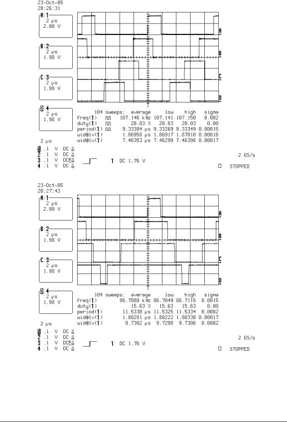
The main application in Example 10 implements the same EINT[0:3] generation sequence as Example 9(b), but does not use the interrupt keyword in its handler definitions (as demonstrated by Example 9(c)). Example 10(a) links against an IRQ ISR that does not implement interrupt nesting (essentially repeating Example 9(b)), while Example 10(b) links against an IRQ ISR that implements nesting (i.e., Example 10(b) does not call the function irq_handler()). Figure 10 shows the waveforms from the two tests. Figure 10(b) shows that successive higher-priority interrupts successively interrupt the currently executing handler.
37

AR1803 |
May 10, 2006 |
(a)
(b)
Figure 10: LPC2138 nested interrupt handling. Example 10 starts by generating a software interrupt on EINT3, and then each IRQ handler generates a software interrupt on the next higher-priority interrupt (except for EINT0, that handler leaves it to main to restart the process). Figure (a) used a IRQ ISR that does not implement interrupt nesting, while Figure (b) used a IRQ ISR that implements interrupt nesting.
38

AR1803 |
May 10, 2006 |
4 µCOS-II RTOS
The MicroC/OS-II or µCOS-II real-time operating system (RTOS) was developed by Jean Labrosse for use in embedded systems such as microcontrollers and DSPs. The RTOS and methods for writing device drivers for it are covered in his two books; MicroC/OS-II: The Real-Time Kernel [6], and Embedded Systems Building Blocks: Complete and Ready-to-Use Modules in C [8]. The second edition of the RTOS book covers version 2.52 of the RTOS. The books contain the RTOS source code, and the RTOS can be used free-of-charge in university projects. The current commercial release of the RTOS is version 2.7x. The web site www.micruim.com contains additional resources, and ports for various processors.
Porting µCOS-II version 2.52 is covered in Chapter 13 of MicroC/OS-II: The Real-Time Kernel, 2nd Ed [6]. A µCOS-II port requires the definition of the data types on the processor, assembly language routines for critical section protection, interrupt handling, and context switching, and the definition of C coded hook functions. Table 13.1 on p289 [6] summarizes the porting requirements. The main e ort involved in porting µCOS-II is to determine the processor programming model, the calling conventions of the compiler, and servicing of interrupts. Earlier sections of this document developed this knowledge, so the port of µCOS-II is now straightforward.
4.1ARM-GCC port description
A task in µCOS-II is defined as a function call of the form;
void task(void *pdata);
where pdata is a pointer that can be used to pass information to a task. Tasks start out life as if they were just interrupted at the entry of a call to their task function. The port-specific C-function OSTaskStkInit() is responsible for creating an appropriate initial stack.
Figure 11 shows the µCOS-II ARM task initial stack context. The ordering of registers on the stack is as per the load/store multiple instruction format; registers with lower numbers are stored at lower addresses (higher on the stack in the figure) (pp60-63 of Furber’s book has a nice description of the load/store multiple instructions [5]). Given this stack layout, with the processor in user/system mode, with the user/system mode stack pointer set to the task context, the state of the task can be restored using the sequence;
/* Copy the task CPSR to the CPSR register */ ldmfd sp!, {r0}
msr cpsr, r0
/* Restore task state (using load multiple) */ ldmfd sp!, {r0-r12, lr, pc}
Note that unlike the sequence used to return from an interrupt, this load multiple instruction does not end with a caret, ‘^’, so the SPSR is not copied to the CPSR when the program counter is loaded (in fact, since you are in system mode, there is no SPSR and so that form of the instruction is illegal (p131 [5])). Another consequence of this choice of return sequence is that since the CPSR is loaded prior to loading the task registers, FIQ and IRQ interrupts will be enabled just prior to restoring the task state (this is fine though).
Most of the registers shown in Figure 11 can take on arbitrary values when an initial task context switch occurs. To aid in debugging, the registers are loaded with hexidecimal values that match their decimal register register numbers packed into a byte, and repeated four times (since debuggers often display the register contents in hexidecimal). The task argument pdata is placed on the stack at the location of r0, while the address of the task function is placed on the task stack at the location of
39

AR1803 |
|
|
|
|
May 10, 2006 |
||||
|
Lower |
|
|
|
|
|
|||
|
addresses |
|
|
Initial |
|||||
|
|
|
|
|
|
|
values |
||
|
|
|
|
|
|
|
|
|
|
|
SP |
|
|
|
CPSR |
|
SYS_MODE |
|
|
|
|
|
|
|
|
||||
|
|
|
|
|
R0 |
|
pdata |
|
|
|
|
|
|
|
R1 |
|
0x01010101 |
|
|
|
|
|
|
|
R2 |
|
0x02020202 |
|
|
|
|
|
|
|
R3 |
|
0x03030303 |
|
|
|
|
|
|
|
R4 |
|
0x04040404 |
|
|
|
|
|
|
|
R5 |
|
0x05050505 |
|
|
|
Stack |
|
|
R6 |
|
0x06060606 |
|
|
|
|
|
|
|
|
|
||||
|
|
|
R7 |
|
0x07070707 |
|
|
||
|
growth |
|
|
|
|
||||
|
|
|
R8 |
|
0x08080808 |
|
|
||
|
|
|
|
|
|
|
|||
|
|
|
|
|
R9 |
|
0x09090909 |
|
|
|
|
|
|
|
R10 |
|
0x10101010 |
|
|
|
|
|
|
|
R11/FP |
|
0x11111111 |
|
|
|
|
|
|
|
R12/IP |
|
0x12121212 |
|
|
|
|
|
|
|
R14/LR |
|
0x14141414 |
|
|
|
Higher |
R15/PC |
|
task |
|
|
|||
|
addresses |
|
|
|
|
|
|||
Figure 11: µCOS-II ARM task initial stack context.
the program counter pc. The current program status register (CPSR) value is set to system mode, with FIQ and IRQ interrupts enabled.
The return address located at the link register location in the stack frame shown in Figure 11 would be used if the task function was ever returned from. Given the link-register value shown in Figure 11, the processor will almost certainly abort, so it can be useful to place the address of an exit handler on the stack in that location. The exit handler can log the fact that a task exited (when it probably should not have).
The Micrium web site hosts a number of ports for the ARM processor. The ports page can be accessed from the Micrium home page at http://www.micrium.com. The address of the ARM ports page was http://www.micrium.com/contents/products/ucos-ii/ports-arm.html when this document was written. The Micrium ARM-mode µCOS-II port is described in Application note AN-1011 (revision D). The port is for the IAR compiler. Several other application notes apply the generic ARM port to specific processors. A port of the AN-1011 port to the GCC compiler is provided with the source code associated with this document.
The Micrium ARM ports do not support interrupt nesting; even for the case of an FIQ interrupt occurring during IRQ interrupt processing (the IRQ interrupt service routine, OS_CPU_IRQ_ISR, in os_cpu_a.s calls the handler function with both IRQ and FIQ interrupts disabled).
The ARM port described in the following sections implements interrupt nesting of IRQ interrupts by FIQ interrupts, and higher-priority IRQ interrupts. The assembler implementation of the port manipulates registers specific to the ARM vectored interrupt controller (VIC). Porting this code for a di erent interrupt controller would be fairly simple.
The only di erence between the AN1011 source code and the code for this port is in the assembly file. The two versions of the assembler files are laid very similarly (in the style of the original AN1011 source). The following sections describe the port files.
Note that the µCOS-II source code is not free, so it is not supplied with this document. The version of the the µCOS-II source code used to test this port was version 2.52; the source provided with the 2nd edition of the Labrosse book.
40
