

Embedded system development and labs for ARM (R. Muresan, 2005)
.pdfEmbedded Systems Development and Labs; The English Edition
2.4 The Usage of Embest IDE
2.4.1 Embest IDE Main Window
To step into Embest IDE for ARM, just run Embest IDE.exe. Embest IDE user interface consists of an integrated set of windows, tools, menus, directories, and other elements that allow you to create, test, and debug your applications. The main window of Embest IDE is shown in Figure 2-26. The Embest IDE main Window includes Title Bar, Menu Bar (1), Tools Bar (2), Project Management Window (3), Data Watch Window (4), Status Bar (5), Memory Window (6), Output Window (7), Variable Window (8), Stack Window (9), Register Window (10) and Source Code Window (11).
Figure 2-26 Embest IDE Main Window
2.4.2 Project Management
1. An Introduction to the Project Manager
The project is an important concept for Embest IDE. It is a basic architecture for users to organize source files, set compile and linking options, generate debug information, and finally generate the BIN file for the target processor. The Embest IDE project management functions include:
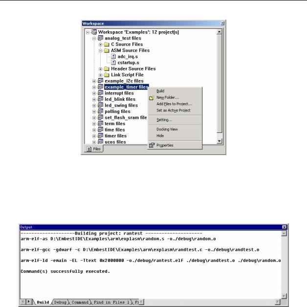
(1) File management in a Project Management Window (Figure2-27).
51
Embedded Systems Development and Labs; The English Edition
Figure2-27 Project Management Window
(2)Provides dialogs for microprocessor/debug device selection and settings, configuration of debug information, compiler/assembly/linker settings, etc.
(3)Provides Build menu and tool buttons and output build information the Build page in Output Window (Figure 2-28).
Figure 2-28 Build Page of Output Window
2. Create a Project
A workspace consists of one or multiple projects. The steps of creating a project are the followings:
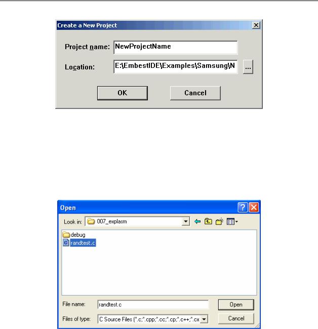
(1)Select FileÆ New Workspace, IDE will prompt a dialog for creating a new project. The dialog box is shown in Figure 2-29.
(2)Fill in the project name, use the default directory or select another directory for saving the project.
(3)Click OK. A new project will be created. A new workspace with the same name as the project’s name will also be created. Also for an existing workspace new projects can be added by right clicking the workspace name in the Project Management Window.
52
Embedded Systems Development and Labs; The English Edition
Figure 2-29 Crate a New Project
3. Create New Source File
Select FileÆ New, IDE will open a new edit window without a title. The user can input and edit source code in this window and save it.
4. Add Files to Project
Select ProjectÆAdd To ProjectÆFiles or right click the project name bar in the Project Management Window and the IDE will open a new dialog box for file selection. This is shown in Figure 2-30.
Figure 2-30 Add Source Files to a Project
5. Set Active Project
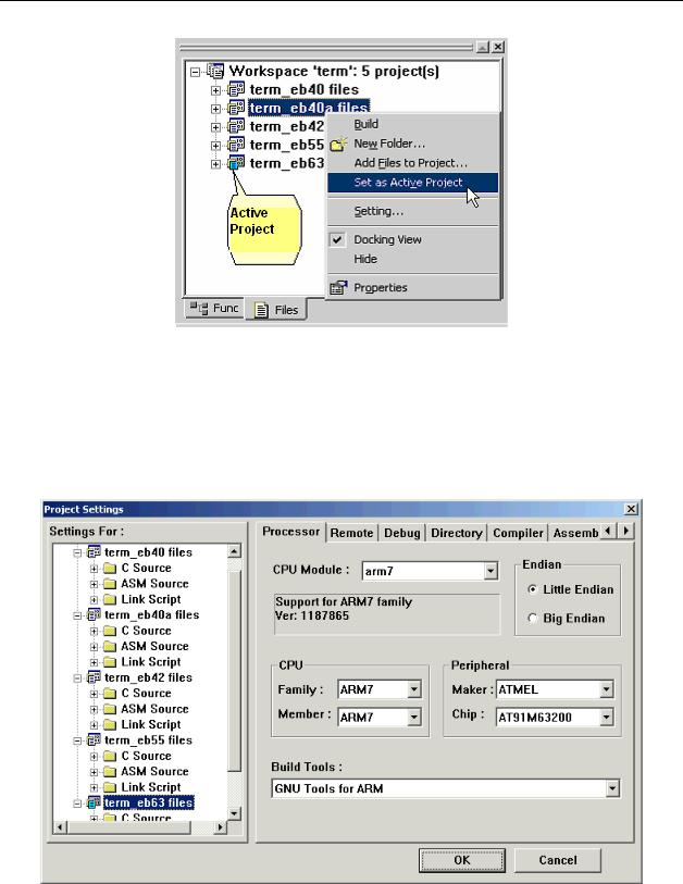
If there are more than one project in the workspace, the user can activate any of these projects by right clicking the project and select “Set as Active Project”. This is shown in Figure 2-31.
53
Embedded Systems Development and Labs; The English Edition
Figure 2-31 Color Icon and Right Click to Select Active Project
2.4.3 Project Basic Settings 1. Processor Settings
Select ProjectÆSettings… The IDE will open a new dialog box. Select the “Processor” page as shown in Figure 2-32. Embest IDE for ARM supports ARM series microprocessor and GNU build tools.
Figure 2-32 Processor Settings Dialog
2. Emulator Settings
54
Embedded Systems Development and Labs; The English Edition
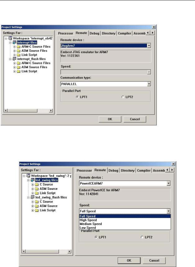
Select ProjectÆSettings… The IDE will open a new dialog box. Select the “Remote” page shown in
Figure 2-33.
Figure 2-33 Emulator Connection Settings Dialog
If the software emulator is used, the “Simarm7” should be selected. If Power ICE is used, the “PowerIceArm7” should be selected. If a parallel port cable is used in connecting PC and ICE, “Parallel Port” should be selected. Only the emulator supported download speed is valid when you select the download speed for emulators. Power ICE for ARM supports all speeds.
Figure 2-34 Embest Power ICE for ARM Emulator Download Speed Support
55
Embedded Systems Development and Labs; The English Edition
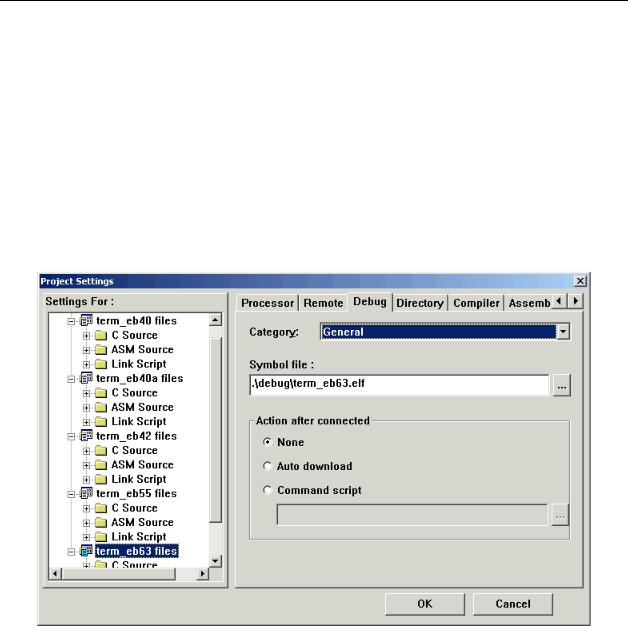
3. Debugging Settings
The debug related settings are shown in Figure 2-35. There are the following three options: 1) General
●Download file: Symbol file name and its directory. Symbol file includes debug information. Normally symbol file is an elf format file or a coff format file.
●Action after connected: There are three ways for selection:
¾None -- No actions after the IDE connected to target.
¾Auto download – After the IDE is connected to the target, the file will be automatically downloaded to the board.
¾Command script -- After the IDE is connected to the target, a script file will be executed first.
Figure 2-35 Debug General Settings
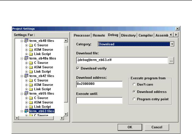
2) Download Settings
Download settings page is shown in Figure 2-36.
●Download file: Symbol file name and its directory. Symbol file includes debug information. Normally the symbol file is an elf format file or a binary file. When download as an elf file the system will automatically convert it into a binary file.
●Download verification: Automatically compare the downloaded file if it is the same as the original file.
●Download address: The downloaded file will be stored from this address.
●Execute program from:
¾Don’t care – After download the system’s PC (program counter) will not change.
¾Download address – After download the system will execute from this address.
56
Embedded Systems Development and Labs; The English Edition
¾Program entry point -- After download, the system will set the PC to the program entry point.
●Execute until: The last symbol the system will execute after the download.
Figure 2-36 Debug Download Settings
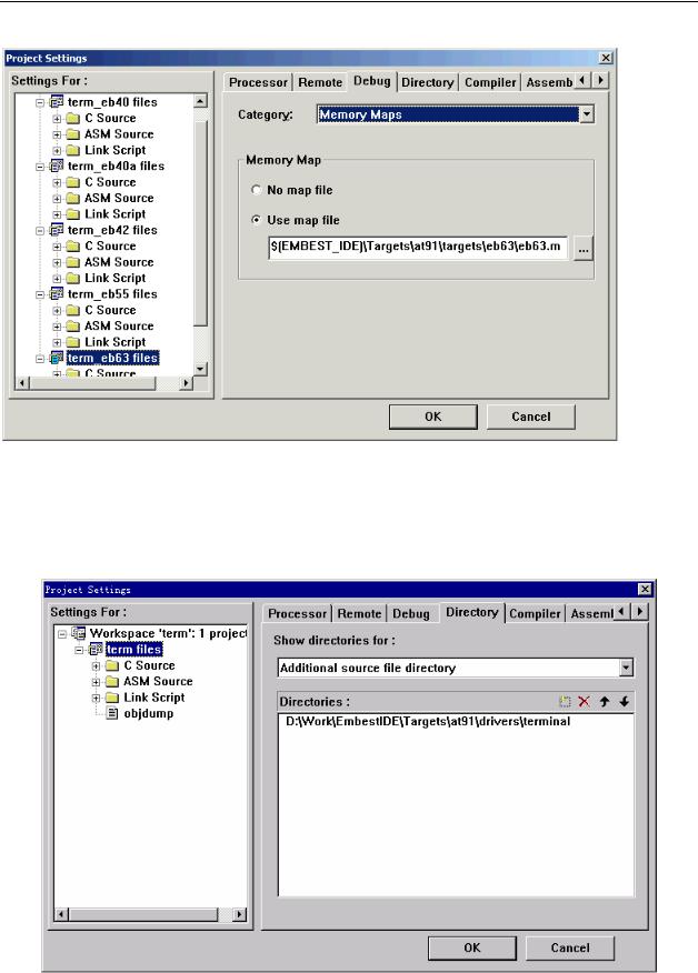
3) Memory Maps Settings
If the memory map file is used, select this item. Map file is used to control the memory read and write as shown in Figure 2-32.
57
Embedded Systems Development and Labs; The English Edition
Figure 2-37 Debug Memory Maps Settings
4. Directory Settings
If users want to trace driver function library and programs in function library, select this item. Shown in Figure 2-37.
58
Embedded Systems Development and Labs; The English Edition
Figure 2-38 Directory Settings Dialog
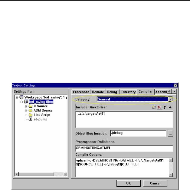
5. Compiler Settings
The compiler settings are shown in Figure 2-39. All of the settings in this page will be displayed in the “Compile Options” edit window. The users can manually edit the Compile Options but need to follow the GNU rules.
a) Compiler General Settings
The compiler general setting is shown in Figure 2-39.
●Include Directory – header files directory.
●Object files location – the directory of object files.
●Preprocessor Definitions – Define the pre-compile micros.
Figure 2-39 Compiler General Settings
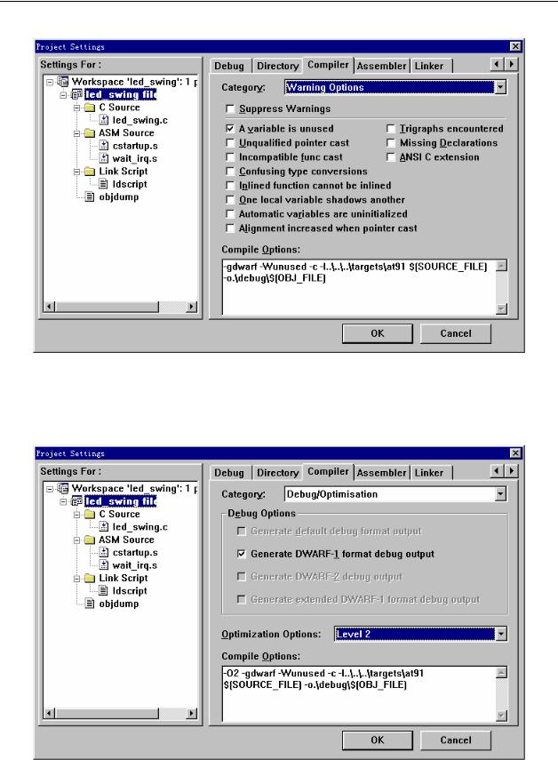
b) Compiler Warning Options
The compiler warning setting is shown in Figure 2-40.
59
Embedded Systems Development and Labs; The English Edition
Figure 2-40 Compiler Warning Settings
c) Compiler Debug/Optimization Settings
The compiler debug/optimization setting is shown in Figure 2-41.
Figure 2-41 Compiler Debug/Optimization Settings
60