

Embedded Robotics (Thomas Braunl, 2 ed, 2006)
.pdf17 Real-Time Image Processing
0 0 0 0 0 0 0 0 0 0 0 1 0
0 0 0 0 0 0 0 0 0 0 1 1 1
0 0 0 0 0 0 0 0 0 0 1 1 0
0 0 0 0 0 0 0 0 0 0 0 1 0
0 2 0 0 0 0 0 0 0 0 0 0 0
2 2 2 0 0 0 0 0 0 0 0 2 2
2 2 2 2 2 0 2 0 0 2 2 2 2
2 2 2 2 2 2 2 2 2 2 2 2 2
Input image |
Segmented image |
Figure 17.10: Segmentation example
If, as for many applications, identifying rectangular areas is sufficient, then the task becomes relatively simple. For now, we assume there is at most a single coherent object of each color class present in the image. For more objects of the same color class, the algorithm has to be extended to check for coherence. In the simple case, we only need to identify four parameters for each color class, namely top left and bottom right corner, or in coordinates:
[xtl, ytl], [xbr, ybr]
Finding these coordinates for each color class still requires a loop over all pixels of the segmented image, comparing the indices of the current pixel position with the determined extreme (top/left, bottom/right) positions of the previously visited pixels of the same color class.
17.8 Image Coordinates versus World Coordinates
Image coordinates
World coordinates
Whenever an object is identified in an image, all we have is its image coordinates. Working with our standard 60u80 resolution, all we know is that our desired object is, say, at position [50, 20] (i.e. bottom left) and has a size of 5u7 pixels. Although this information might already be sufficient for some simple applications (we could already steer the robot in the direction of the object), for many applications we would like to know more precisely the object’s location in world coordinates relative from our robot in meters in the x- and y-direction (see Figure 17.11).
For now, we are only interested in the object’s position in the robot’s local coordinate system {x´, y´}, not in the global word coordinate system {x, y}. Once we have determined the coordinates of the object in the robot coordinate system and also know the robot’s (absolute) position and orientation, we can transform the object’s local coordinates to global world coordinates.
As a simplification, we are looking for objects with rotational symmetry, such as a ball or a can, because they look the same (or at least similar) from any viewing angle. The second simplification is that we assume that objects are not floating in space, but are resting on the ground, for example the table the robot is driving on. Figure 17.12 demonstrates this situation with a side
258
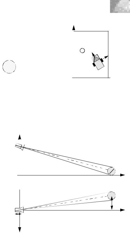
Image Coordinates versus World Coordinates
|
|
|
|
|
|
|
y |
||
|
|
|
|
|
|
|
|
|
|
0 0 |
0 |
0 |
0 |
0 |
0 |
0 |
|
´ |
|
0 0 |
0 |
0 |
0 |
0 |
0 |
0 |
|
|
y |
|
|
|
|||||||
0 0 |
0 |
0 |
0 |
0 |
0 |
0 |
|
|
|
0 0 |
0 |
0 |
0 |
0 |
0 |
0 |
|
|
|
0 0 |
1 |
0 |
0 |
0 |
0 |
0 |
|
|
|
0 1 |
1 |
1 |
0 |
0 |
0 |
0 |
|
|
|
0 1 |
1 |
0 |
0 |
0 |
0 |
0 |
|
|
|
0 0 |
0 |
0 |
0 |
0 |
0 |
0 |
|
|
|
Robot image data |
|
|
World view |
||||||
Figure 17.11: Image and world coordinates
 x´
x´
 x
x
view and a top view from the robot’s local coordinate system. What we have to determine is the relationship between the ball position in local coordinates [x´, y´] and the ball position in image coordinates [j, i]:
y´ = f (i, h, D, f, d) x´ = g (j, 0, E, f, d)
z´
i = y´ object size |
|
camera angle D (about x) |
|
||
in [pixels] |
|
|
camera height h |
|
|
|
|
|
ball size  d
d
|
|
|
y´ |
ball y´-position in [m] |
|
||
|
camera angle E |
ball x´-pos. |
|
j = x´ object size |
(about z) |
||
in [m] |
|||
in [pixels] |
|
y´ |
|
camera focal length f |
|||
|
|||
in [m] |
|
|
|
x´ |
|
|
|
Figure 17.12: Camera position and orientation
259

17 Real-Time Image Processing
It is obvious that f and g are the same function, taking as parameters:
•One-dimensional distance in image coordinates (object’s length in image rows or columns in pixels)
•Camera offset
(height in y´z´ view, 0 side offset in x´y´ view)
•Camera rotation angle (tilt or pan)
•Camera focal length
(distance between lens and sensor array)
•Ball size (diameter d)
Provided that we know the detected object’s true physical size (for example golf ball for robot soccer), we can use the intercept theorem to calculate its local displacement. With a zero camera offset and a camera angle of zero (no tilting or panning), we have the proportionality relationships:
yc |
d |
xc |
d |
---- |
a -- |
---- |
a -- |
f |
i |
f |
j |
These can be simplified when introducing a camera-specific parameter g = k · f for converting between pixels and meters:
y´ = g · d / i x´ = g · d / j
So in other words, the larger the image size in pixels, the closer the object is. The transformation is just a constant linear factor; however, due to lens distortions and other sources of noise these ideal conditions will not be observed in an experiment. It is therefore better to provide a lookup table for doing the transformation, based on a series of distance measurements.
With the camera offset, either to the side or above the driving plane, or placed at an angle, either panning about the z-axis or tilting about the x-axis, the trigonometric formulas become somewhat more complex. This can be solved either by adding the required trigonometric functions to the formulas and calculating them for every image frame, or by providing separate lookup tables from all camera viewing angles used. In Section 18.5 this method is applied to robot soccer.
17.9 References
BÄSSMANN, H., BESSLICH, P. Ad Oculos: Digital Image Processing, International Thompson Publishing, Washington DC, 1995
BLAKE, A., YUILLE, A. (Eds.) Active Vision, MIT Press, Cambridge MA, 1992
260

References
BRÄUNL, T. Parallel Image Processing, Springer-Verlag, Berlin Heidelberg, 2001
BRÄUNL, T. Improv – Image Processing for Robot Vision, http://robotics. ee.uwa.edu.au/improv, 2006
CHO, H., LEE., J.-J. (Ed.) 2002 FIRA Robot World Congress, Proceedings, Korean Robot Soccer Association, Seoul, May 2002
FAUGERAS, O. Three-Dimensional Computer Vision, MIT Press, Cambridge MA, 1993
GONZALES, R., WOODS, R., Digital Image Processing, 2nd Ed., Prentice Hall, Upper Saddle River NJ, 2002
HEARN, D., BAKER, M. Computer Graphics - C Version, Prentice Hall, Upper Saddle River NJ, 1997
KAMINKA, G. LIMA, P., ROJAS, R. (Eds.) RoboCup 2002: Robot Soccer World Cup VI, Proccedings, Fukuoka, Japan, Springer-Verlag, Berlin Heidelberg, 2002
KLETTE, R., PELEG, S., SOMMER, G. (Eds.) Robot Vision, Proceedings of the International Workshop RobVis 2001, Auckland NZ, Lecture Notes in Computer Science, no. 1998, Springer-Verlag, Berlin Heidelberg, Feb. 2001
KORTENKAMP, D., NOURBAKHSH, I., HINKLE, D. The 1996 AAAI Mobile Robot
Competition and Exhibition, AI Magazine, vol. 18, no. 1, 1997, pp. 2532 (8)
LECLERCQ, P., BRÄUNL, T. A Color Segmentation Algorithm for Real-Time Object Localization on Small Embedded Systems, Robot Vision 2001, International Workshop, Auckland NZ, Lecture Notes in Computer Science, no. 1998, Springer-Verlag, Berlin Heidelberg, Feb. 2001, pp. 69-76 (8)
NALWA, V. A Guided Tour of Computer Vision, Addison-Wesley, Reading MA, 1993
PARKER, J. Algorithms for Image Processing and Computer Vision, John Wiley & Sons, New York NY, 1997
261

R. . .OBOT. . . . . . . . . S. . .OCCER. . . . . . . . . . . . . . . . . . . . |
|
18 |
|
|
|
.. . . . . . . . |
|
|
Football, or soccer as it is called in some countries, is often referred to as “the world game”. No other sport is played and followed by as many nations around the world. So it did not take long to establish the idea of robots playing soccer against each other. As has been described earlier on the Micro Mouse Contest, robot competitions are a great opportunity to share new
ideas and actually see good concepts at work.
Robot soccer is more than one robot generation beyond simpler competitions like solving a maze. In soccer, not only do we have a lack of environment structure (less walls), but we now have teams of robots playing an opposing team, involving moving targets (ball and other players), requiring planning, tactics, and strategy – all in real time. So, obviously, this opens up a whole new dimension of problem categories. Robot soccer will remain a great challenge for years to come.
18.1 RoboCup and FIRA Competitions
See details at: www.fira.net www.robocup.org
Today, there are two world organizations involved in robot soccer, FIRA and RoboCup. FIRA [Cho, Lee 2002] organized its first robot tournament in 1996 in Korea with Jong-Hwan Kim. RoboCup [Asada 1998] followed with its first competition in 1997 in Japan with Asada, Kuniyoshi, and Kitano [Kitano et al. 1997], [Kitano et al. 1998].
FIRA’s “MiroSot” league (Micro-Robot World Cup Soccer Tournament) has the most stringent size restrictions [FIRA 2006]. The maximum robot size is a cube of 7.5cm side length. An overhead camera suspended over the playing field is the primary sensor. All image processing is done centrally on an off-board workstation or PC, and all driving commands are sent to the robots via wireless remote control. Over the years, FIRA has added a number of different leagues, most prominently the “SimuroSot” simulation league and the “RoboSot” league for small autonomous robots (without global vision). In 2002, FIRA introduced “HuroSot”, the first league for humanoid soccer playing robots. Before that all robots were wheel-driven vehicles.
263263

18 Robot Soccer
Real robots don’t use global vision!
RoboCup started originally with the “Small-Size League”, “Middle-Size League”, and “Simulation League” [RoboCup 2006]. Robots of the small-size league must fit in a cylinder of 18cm diameter and have certain height restrictions. As for MiroSot, these robots rely on an overhead camera over the playing field. Robots in the middle-size league abolished global vision after the first two years. Since these robots are considerably larger, they are mostly using commercial robot bases equipped with laptops or small PCs. This gives them at least one order of magnitude higher processing power; however, it also drives up the cost for putting together such a robot soccer team. In later years, RoboCup added the commentator league (subsequently dropped), the rescue league (not related to soccer), the “Sony 4-legged league” (which, unfortunately, only allows the robots of one company to compete), and finally in 2002 the “Humanoid League”.
The following quote from RoboCup’s website may in fact apply to both organizations [RoboCup 2006]:
“RoboCup is an international joint project to promote AI, robotics, and related fields. It is an attempt to foster AI and intelligent robotics research by providing a standard problem where a wide range of technologies can be integrated and examined. RoboCup chose to use the soccer game as a central topic of research, aiming at innovations to be applied for socially significant problems and industries. The ultimate goal of the RoboCup project is: By 2050, develop a team of fully autonomous humanoid robots that can win against the human world champion team in soccer.”
We will concentrate here on robot soccer played by wheeled robots (humanoid robot soccer is still in its infancy) without the help of global vision. The RoboCup Small-Size League, but not the Middle-Size League or FIRA RoboSot, allows the use of an overhead camera suspended above the soccer field. This leads teams to use a single central workstation that does the image processing and planning for all robots. There are no occlusions: ball, robots, and goals are always perfectly visible. Driving commands are then issued via wireless links to individual “robots”, which are not autonomous at all and in some respect reduced to remote control toy cars. Consequently, the “AllBots” team from Auckland, New Zealand does in fact use toy cars as a low-budget alternative [Baltes 2001a]. Obviously, global vision soccer is a completely different task to local vision soccer, which is much closer to common research areas in robotics, including vision, self-localization, and distributed planning.
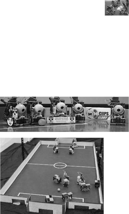
The robots of our team “CIIPS Glory” carry EyeCon controllers to perform local vision on-board. Some other robot soccer teams, like “4 Stooges” from Auckland, New Zealand, use EyeCon controllers as well [Baltes 2001b].
Robot soccer teams play five-a-side soccer with rules that are freely adapted from FIFA soccer. Since there is a boundary around the playing field, the game is actually closer to ice hockey. The big challenge is not only that reliable image processing has to be performed in real time, but also that a team of five robots/actors has to be organized. In addition, there is an opposing team which
264
RoboCup and FIRA Competitions
will change the environment (for example kick the ball) and thereby render one’s own action plans useless if too slow.
One of the frequent disappointments of robot competitions is that enormous research efforts are reduced to “show performance” in a particular event and cannot be appreciated adequately. Adapting from the home lab environment to the competition environment turns out to be quite tricky, and many programs are not as robust as their authors had hoped. On the other hand, the actual competitions are only one part of the event. Most competitions are part of conferences and encourage participants to present the research behind their competition entries, giving them the right forum to discuss related ideas.
Mobile robot competitions brought progress to the field by inspiring people and by continuously pushing the limits of what is possible. Through robot competitions, progress has been achieved in mechanics, electronics, and algorithms [Bräunl 1999].
CIIPS Glory with local vision on each robot
Note the colored patches on top of the Lilliputs players. They need them to determine each robot’s position and orientation with global vision.
Figure 18.1: CIIPS Glory line-up and in play vs. Lilliputs (1998)
265
18 Robot Soccer
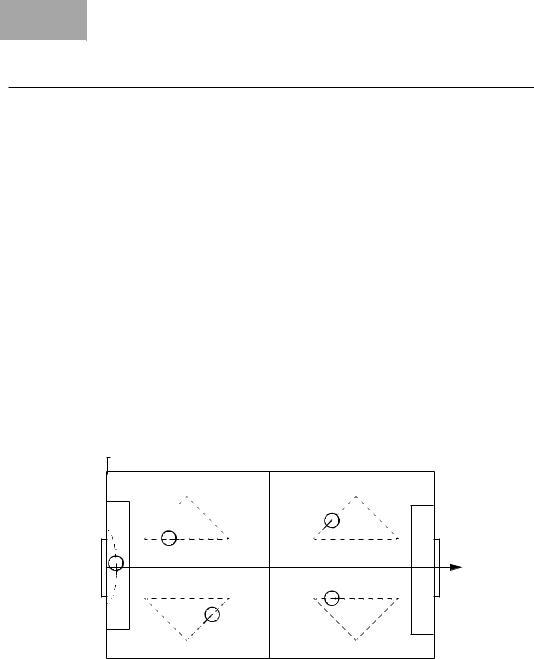
18.2 Team Structure
The CIIPS Glory robot soccer team (Figure 18.1) consists of four field players and one goal keeper robot [Bräunl, Graf 1999], [Bräunl, Graf 2000]. A local intelligence approach has been implemented, where no global sensing or control system is used. Each field player is equipped with the same control software, only the goal keeper – due to its individual design and task – runs a different program.
Different roles (left/right defender, left/right attacker) are assigned to the four field players. Since the robots have a rather limited field of view with their local cameras, it is important that they are always spread around the whole field. Therefore, each player’s role is linked to a specific area of the field. When the ball is detected in a certain position, only the robot responsible for this area is meant to drive toward and play the ball. The robot which has detected the ball communicates the position of the ball to its team mates which try to find favorable positions on the field to be prepared to take over and play the ball as soon as it enters their area.
Situations might occur when no robot sees the ball. In that case, all robots patrol along specific paths in their assigned area of the field, trying to detect the ball. The goal keeper usually stays in the middle of the goal and only moves once it has detected the ball in a reasonably close position (Figure 18.2).
 y
y
x
Figure 18.2: Robot patrolling motion
This approach appears to be quite efficient, especially since each robot acts individually and does not depend on any global sensing or communication system. For example, the communication system can be switched off without any major effects; the players are still able to continue playing individually.
266

Mechanics and Actuators
18.3 Mechanics and Actuators
According to the RoboCup Small-Size League and FIRA RoboSot regulations the size of the SoccerBots has been restricted to 10cm by 15cm. The height is also limited, therefore the EyeCon controller is mounted on a mobile platform at an angle. To catch the ball, the robot has a curved front. The size of the curved area has been calculated from the rule that at least two-thirds of the ball’s projected area must be outside the convex hull around the robot. With the ball having a diameter of approximately 4.5cm, the depth of the curved front must be no more than 1.5cm.
The robots are equipped with two motorized wheels plus two casters at the front and back of the vehicle. Each wheel is controlled separately, which enables the robots to drive forward, backward, as well as drive in curves or spin on the spot. This ability for quick movement changes is necessary to navigate successfully in rapidly changing environments such as during robot soccer competitions.
Two additional servo motors are used to activate a kicking device at the front of the robot and the movement of the on-board camera.
In addition to the four field players of the team, one slightly differing goal keeper robot has been constructed. To enable it to defend the goal successfully it must be able to drive sideways in front of the goal, but look and kick forward. For this purpose, the top plate of the robot is mounted at a 90° angle to the bottom plate. For optimal performance at the competition, the kicking device has been enlarged to the maximum allowed size of 18cm.
18.4 Sensing
Sensing a robot’s environment is the most important part for most mobile robot applications, including robot soccer. We make use of the following sensors:
•Shaft encoders
•Infrared distance measurement sensors
•Compass module
•Digital camera
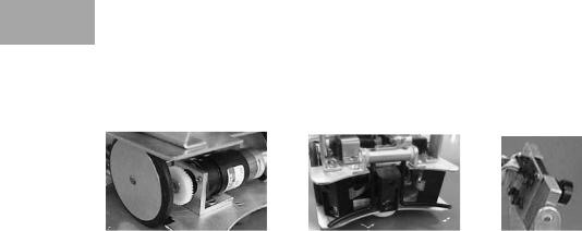
In addition, we use communication between the robots, which is another source of information input for each robot. Figure 18.3 shows the main sensors of a wheeled SoccerBot in detail.
Shaft encoders The most basic feedback is generated by the motors’ encapsulated shaft encoders. This data is used for three purposes:
•PI controller for individual wheel to maintain constant wheel speed.
•PI controller to maintain desired path curvature (i.e. straight line).
•Dead reckoning to update vehicle position and orientation.
267
18 Robot Soccer
The controller’s dedicated timing processor unit (TPU) is used to deal with the shaft encoder feedback as a background process.
Figure 18.3: Sensors: shaft encoder, infrared sensors, digital camera
Infrared distance measurement
Each robot is equipped with three infrared sensors to measure the distance to the front, to the left, and to the right (PSD). This data can be used to:
•Avoid collision with an obstacle.
•Navigate and map an unknown environment.
•Update internal position in a known environment.
Compass module
Digital camera
Robot-to-robot communication
Since we are using low-cost devices, the sensors have to be calibrated for each robot and, due to a number of reasons, also generate false readings from time to time. Application programs have to take care of this, so a level of software fault tolerance is required.
The biggest problem in using dead reckoning for position and orientation estimation in a mobile robot is that it deteriorates over time, unless the data can be updated at certain reference points. A wall in combination with a distance sensor can be a reference point for the robot’s position, but updating robot orientation is very difficult without additional sensors.
In these cases, a compass module, which senses the earth’s magnetic field, is a big help. However, these sensors are usually only correct to a few degrees and may have severe disturbances in the vicinity of metal. So the exact sensor placement has to be chosen carefully.
We use the EyeCam camera, based on a CMOS sensor chip. This gives a resolution of 60 u 80 pixels in 32bit color. Since all image acquisition, image processing, and image display is done on-board the EyeCon controller, there is no need to transmit image data. At a controller speed of 35MHz we achieve a frame capture rate of about 7 frames per second without FIFO buffer and up to 30 fps with FIFO buffer. The final frame rate depends of course on the image processing routines applied to each frame.
While the wireless communication network between the robots is not exactly a sensor, it is nevertheless a source of input data to the robot from its environment. It may contain sensor data from other robots, parts of a shared plan, intention descriptions from other robots, or commands from other robots or a human operator.
268