
Embedded Robotics (Thomas Braunl, 2 ed, 2006)
.pdf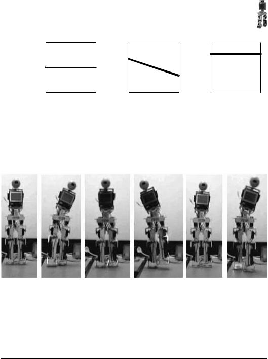
Dynamic Balance
Robot in balance |
Robot falling left |
Robot falling forward |
Figure 10.8: Artificial horizon
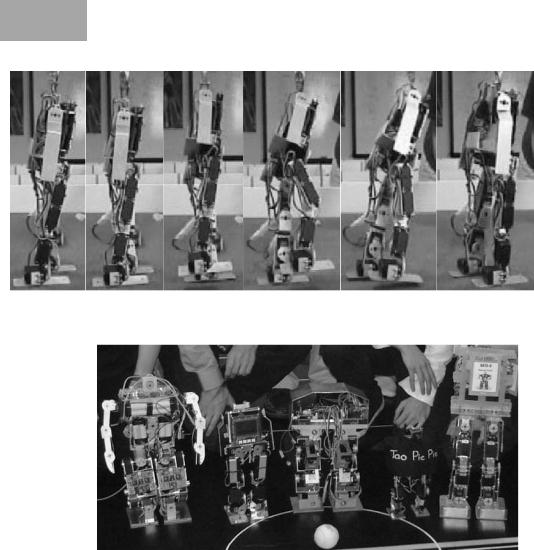
Figure 10.9 shows Johnny Walker during a walking cycle. Note the typical side-swing of the torso to counterbalance the leg-lifting movement. This creates a large momentum around the robot’s center of mass, which can cause problems with stability due to the limited accuracy of the servos used as actuators.
Figure 10.9: Johnny walking sequence
Figure 10.10 shows a similar walking sequence with Andy Droid. Here, the robot performs a much smoother and better controlled walking gait, since the mechanical design of the hip area allows a smoother shift of weight toward the side than in Johnny’s case.
10.5.2 Alternative Biped Designs
All the biped robots we have discussed so far are using servos as actuators. This allows an efficient mechanical and electronic design of a robot and therefore is a frequent design approach in many research groups, as can be seen from the group photo of FIRA HuroSot World Cup Competition in 2002 [Baltes, Bräunl 2002]. With the exception of one robot, all robots were using servos (see Figure 10.11).
145
10 Walking Robots
Figure 10.10: Andy walking sequence
Figure 10.11: Humanoid robots at FIRA HuroSot 2002 with robots from (left to right): Korea, Australia, Singapore, New Zealand, and Korea
Other biped robot designs also using the EyeCon controller are Tao Pie Pie from University of Auckland, New Zealand, and University of Manitoba, Canada, [Lam, Baltes 2002] and ZORC from Universität Dortmund, Germany [Ziegler et al. 2001].
As has been mentioned before, servos have severe disadvantages for a number of reasons, most importantly because of their lack of external feedback. The construction of a biped robot with DC motors, encoders, and endswitches, however, is much more expensive, requires additional motor driver electronics, and is considerably more demanding in software development. So instead of redesigning a biped robot by replacing servos with DC motors and keeping the same number of degrees of freedom, we decided to go for a minimal approach. Although Andy has 10 dof in both legs, it utilizes only three
146
Dynamic Balance
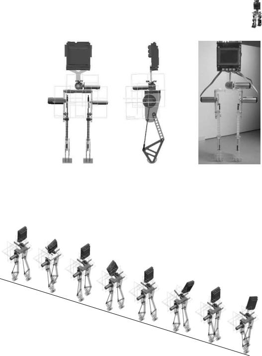
Figure 10.12: Minimal biped design Rock Steady
independent dof: bending each leg up and down, and leaning the whole body left or right. Therefore, it should be possible to build a robot that uses only three motors and uses mechanical gears or pulleys to achieve the articulated joint motion.
Figure 10.13: Dynamic walking sequence
The CAD designs following this approach and the finished robot are shown in Figure 10.12 [Jungpakdee 2002]. Each leg is driven by only one motor, while the mechanical arrangement lets the foot perform an ellipsoid curve for each motor revolution. The feet are only point contacts, so the robot has to
147

10 Walking Robots
keep moving continuously, in order to maintain dynamic balance. Only one motor is used for shifting a counterweight in the robot’s torso sideways (the original drawing in Figure 10.12 specified two motors). Figure 10.13 shows the simulation of a dynamic walking sequence [Jungpakdee 2002].
10.6 References
BALTES. J., BRÄUNL, T. HuroSot - Laws of the Game, FIRA 1st Humanoid Robot Soccer Workshop (HuroSot), Daejeon Korea, Jan. 2002, pp. 43-68 (26)
BOEING, A., BRÄUNL, T. Evolving Splines: An alternative locomotion controller for a bipedal robot, Seventh International Conference on Control, Automation, Robotics and Vision, ICARV 2002, CD-ROM, Singapore, Dec. 2002, pp. 1-5 (5)
BOEING, A., BRÄUNL, T. Evolving a Controller for Bipedal Locomotion, Proceedings of the Second International Symposium on Autonomous Minirobots for Research and Edutainment, AMiRE 2003, Brisbane, Feb. 2003, pp. 43-52 (10)
BRÄUNL, T. Design of Low-Cost Android Robots, Proceedings of the First IEEE-RAS International Conference on Humanoid Robots, Humanoids 2000, MIT, Boston, Sept. 2000, pp. 1-6 (6)
BRÄUNL, T., SUTHERLAND, A., UNKELBACH, A. Dynamic Balancing of a Hu-
manoid Robot, FIRA 1st Humanoid Robot Soccer Workshop (HuroSot), Daejeon Korea, Jan. 2002, pp. 19-23 (5)
CAUX, S., MATEO, E., ZAPATA, R. Balance of biped robots: special double-in- verted pendulum, IEEE International Conference on Systems, Man, and Cybernetics, 1998, pp. 3691-3696 (6)
CHO, H., LEE, J.-J. (Eds.) Proceedings 2002 FIRA Robot World Congress, Seoul, Korea, May 2002
DOERSCHUK, P., NGUYEN, V., LI, A. Neural network control of a three-link leg, in Proceedings of the International Conference on Tools with Artificial Intelligence, 1995, pp. 278-281 (4)
FUJIMOTO, Y., KAWAMURA, A. Simulation of an autonomous biped walking robot including environmental force interaction, IEEE Robotics and Automation Magazine, June 1998, pp. 33-42 (10)
GODDARD, R., ZHENG, Y., HEMAMI, H. Control of the heel-off to toe-off motion of a dynamic biped gait, IEEE Transactions on Systems, Man, and Cybernetics, vol. 22, no. 1, 1992, pp. 92-102 (11)
HARADA, H. Andy-2 Visualization Video, http://robotics.ee.uwa.edu.au /eyebot/mpg/walk-2leg/, 2006
148

References
JUNGPAKDEE, K., Design and construction of a minimal biped walking mechanism, B.E. Honours Thesis, The Univ. of Western Australia, Dept. of Mechanical Eng., supervised by T. Bräunl and K. Miller, 2002
KAJITA, S., YAMAURA, T., KOBAYASHI, A. Dynamic walking control of a biped robot along a potential energy conserving orbit, IEEE Transactions on Robotics and Automation, Aug. 1992, pp. 431-438 (8)
KUN, A., MILLER III, W. Adaptive dynamic balance of a biped using neural networks, in Proceedings of the 1996 IEEE International Conference on Robotics and Automation, Apr. 1996, pp. 240-245 (6)
LAM, P., BALTES, J. Development of Walking Gaits for a Small Humanoid Robot, Proceedings 2002 FIRA Robot World Congress, Seoul, Korea, May 2002, pp. 694-697 (4)
MILLER III, W. Real-time neural network control of a biped walking robot, IEEE Control Systems, Feb. 1994, pp. 41-48 (8)
MONTGOMERY, G. Robo Crop - Inside our AI Labs, Australian Personal Computer, Issue 274, Oct. 2001, pp. 80-92 (13)
NICHOLLS, E. Bipedal Dynamic Walking in Robotics, B.E. Honours Thesis, The Univ. of Western Australia, Electrical and Computer Eng., supervised by T. Bräunl, 1998
PARK, J.H., KIM, K.D. Bipedal Robot Walking Using Gravity-Compensated Inverted Pendulum Mode and Computed Torque Control, IEEE International Conference on Robotics and Automation, 1998, pp. 3528-3533
(6)
RÜCKERT, U., SITTE, J., WITKOWSKI, U. (Eds.) Autonomous Minirobots for Research and Edutainment – AMiRE2001, Proceedings of the 5th International Heinz Nixdorf Symposium, HNI-Verlagsschriftenreihe, no. 97, Univ. Paderborn, Oct. 2001
SUTHERLAND, A., BRÄUNL, T. Learning to Balance an Unknown System, Proceedings of the IEEE-RAS International Conference on Humanoid Robots, Humanoids 2001, Waseda University, Tokyo, Nov. 2001, pp. 385-391 (7)
TAKANISHI, A., ISHIDA, M., YAMAZAKI, Y., KATO, I. The realization of dynam-
ic walking by the biped walking robot WL-10RD, in ICAR’85, 1985, pp. 459-466 (8)
UNKELBACH, A. Analysis of sensor data for balancing and walking of a biped robot, Project Thesis, Univ. Kaiserslautern / The Univ. of Western Australia, supervised by T. Bräunl and D. Henrich, 2002
WICKE, M. Bipedal Walking, Project Thesis, Univ. Kaiserslautern / The Univ. of Western Australia, supervised by T. Bräunl, M. Kasper, and E. von Puttkamer, 2001
149

10 Walking Robots
ZIEGLER, J., WOLFF, K., NORDIN, P., BANZHAF, W. Constructing a Small Hu-
manoid Walking Robot as a Platform for the Genetic Evolution of Walking, Proceedings of the 5th International Heinz Nixdorf Symposium, Autonomous Minirobots for Research and Edutainment, AMiRE 2001, HNI-Verlagsschriftenreihe, no. 97, Univ. Paderborn, Oct. 2001, pp. 51-59 (9)
ZIMMERMANN, J., Balancing of a Biped Robot using Force Feedback, Diploma Thesis, FH Koblenz / The Univ. of Western Australia, supervised by T. Bräunl, 2004
150

A. . .UTONOMOUS. . . . . . . . . . . . . . . . . . . .P. . LANES. . . . . . . . . . |
|
11 |
|
|
|
.. . . . . . . . |
|
|
Building an autonomous model airplane is a considerably more difficult undertaking than the previously described autonomous driving or walking robots. Model planes or helicopters require a significantly higher level of safety, not only because the model plane with its expensive
equipment might be lost, but more importantly to prevent endangering people on the ground.
A number of autonomous planes or UAVs (Unmanned Aerial Vehicles) have been built in the past for surveillance tasks, for example Aerosonde [Aerosonde 2006]. These projects usually have multi-million-dollar budgets, which cannot be compared to the smaller-scale projects shown here. Two projects with similar scale and scope to the one presented here are “MicroPilot” [MicroPilot 2006], a commercial hobbyist system for model planes, and “FireMite” [Hennessey 2002], an autonomous model plane designed for competing in the International Aerial Robotics Competition [AUVS 2006].
11.1 Application
Low-budget Our goal was to modify a remote controlled model airplane for autonomous autopilot flying to a given sequence of waypoints (autopilot).
•The plane takes off under remote control.
•Once in the air, the plane is switched to autopilot and flies to a previously recorded sequence of waypoints using GPS (global positioning system) data.
•The plane is switched back to remote control and landed.
So the most difficult tasks of take-off and landing are handled by a pilot using the remote control. The plane requires an embedded controller to interface to the GPS and additional sensors and to generate output driving the servos.
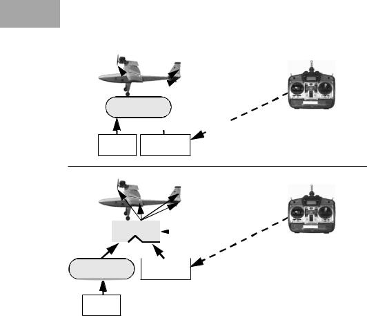
There are basically two design options for constructing an autopilot system for such a project (see Figure 11.1):
151151
11 Autonomous Planes
A
 4
4
Controller 5 
 5
5 
GPS Receiver
B
|
|
|
4 |
|
||
Multiplexer |
|
|
5 |
|||
|
|
|||||
|
|
|
|
|
||
4 |
|
4 |
|
|
1 |
|
Controller Receiver
GPS
Figure 11.1: System design options
A.The embedded controller drives the plane’s servos at all times. It receives sensor input as well as input from the ground transmitter.
B.A central (and remote controlled) multiplexer switches between ground transmitter control and autopilot control of the plane’s servos.
Design option A is the simpler and more direct solution. The controller reads data from its sensors including the GPS and the plane’s receiver. Ground control can switch between autopilot and manual operation by a separate channel. The controller is at all times connected to the plane’s servos and generates their PWM control signals. However, when in manual mode, the controller reads the receiver’s servo output and regenerates identical signals.
Design option B requires a four-way multiplexer as an additional hardware component. (Design A has a similar multiplexer implemented in software.) The multiplexer connects either the controller’s four servo outputs or the receiver’s four servo outputs to the plane’s servos. A special receiver channel is used for toggling the multiplexer state under remote control.
Although design A is the superior solution in principle, it requires that the controller operates with highest reliability. Any fault in either controller hardware or controller software, for example the “hanging” of an application pro-
152
Application
gram, will lead to the immediate loss of all control surfaces and therefore the loss of the plane. For this reason we opted to implement design B. Although it requires a custom-built multiplexer as additional hardware, this is a rather simple electro-magnetic device that can be directly operated via remote control and is not subject to possible software faults.
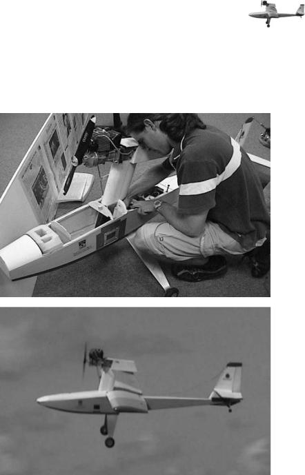
Figure 11.2: Autonomous model plane during construction and in flight
Figure 11.2 shows photos of the construction and during flight of our first autonomous plane. This plane had the EyeCon controller and the multiplexer unit mounted on opposite sides of the fuselage.
153

11 Autonomous Planes
11.2 Control System and Sensors
An EyeCon system is used as on-board flight controller. Before take-off, GPS waypoints for the desired flight path are downloaded to the controller. After the landing, flight data from all on-board sensors is uploaded, similar to the
Black box operation of a “black box” data recorder on a real plane.
The EyeCon’s timing processor outputs generate PWM signals that can directly drive servos. In this application, they are one set of inputs for the multiplexer, while the second set of inputs comes from the plane’s receiver. Two serial ports are used on the EyeCon, one for upload/download of data and programs, and one for continuous GPS data input.
Although the GPS is the main sensor for autonomous flight, it is insufficient because it delivers a very slow update of 0.5Hz .. 1.0Hz and it cannot determine the plane’s orientation. We are therefore experimenting with a number of additional sensors (see Chapter 2 for details of these sensors):
•Digital compass
Although the GPS gives directional data, its update rates are insufficient when flying in a curve around a waypoint.
•Piezo gyroscope and inclinometer
Gyroscopes give the rate of change, while inclinometers return the absolute orientation. The combined use of both sensor types helps reduce the problems with each individual sensor.
•Altimeter and air-speed sensor
Both altimeter and air-speed sensor have been built by using air pressure sensors. These sensors need to be calibrated for different heights and temperatures. The construction of an air-speed sensor requires the combination of two sensors measuring the air pressure at the wing tip with a so-called “Pitot tube”, and comparing the result with a third air pressure sensor inside the fuselage, which can double as a height sensor.
Figure 11.3 shows the “EyeBox”, which contains most equipment required for autonomous flight, EyeCon controller, multiplexer unit, and rechargeable battery, but none of the sensors. The box itself is an important component, since it is made out of lead-alloy and is required to shield the plane’s receiver from any radiation from either the controller or the multiplexer. Since the standard radio control carrier frequency of 35MHz is in the same range as the EyeCon’s operating speed, shielding is essential.
Another consequence of the decision for design B is that the plane has to remain within remote control range. If the plane was to leave this range, unpredictable switching between the multiplexer inputs would occur, switching control of the plane back and forth between the correct autopilot settings and noise signals. A similar problem would exist for design A as well; however, the controller could use plausibility checks to distinguish noise from proper remote control signals. By effectively determining transmitter strength, the controller could fly the plane even outside the remote transmitter’s range.
154
