

Beginers introduction to the Assebly Language of ATMEL-AVR Microprocessors (Gerhard Schmidt,2004, англ)
.pdfAvr-Asm-Tutorial |
27 |
http://www.avr-asm-tutorial.net |
|
|
|
OR R1,R2
Back from an ASCII character to a BCD is as easy. The instruction
ANDI R1,0x0F
isolates the lower four bits (= the lower nibble). Note that ORI and ANDI are only possible with registers above R15. If you need to do this, use one of the registers R16 to R31!
If the hex value 0x0F is already in register R2, you can AND the ASCII character with this register:
AND R1,R2
The other instructions for manipulating bits in a register are also limited for registers above R15. They would be formulated like this:
SBR R16,0b00110000 ; Set bits 4 und 5 to one CBR R16,0b00110000 ; Clear bits 4 and 5 to zero
If one or more bits of a byte have to be inverted you can use the following instruction (which is not possible for use with a constant):
LDI R16,0b10101010 ; Invert all even bits
EOR R1,R16 ; in register R1 and store result in R1
To invert all bits of a byte is called the One's complement:
COM R1
inverts the content in register R1 and replaces zeros by one and vice versa. Different from that is the Two's complement, which converts a positive signed number to its negative complement (subtracting from zero). This is done with the instruction
NEG R1
So +1 (decimal: 1) yields -1 (binary 1.1111111), +2 yields -2 (binary 1.1111110), and so on.
Besides the manipulation of the bits in a register, copying a single bit is possible using the so-called T-bit of the status register. With
BLD R1,0
the bit 0 in register R1 is overwritten with a copy of the T-bit . The T-bit can be set or cleared, and its content can be copied to any bit in any register:
CLT ; clear T-bit, or SET ; set T-bit, or
BST R2,2 ; copy register R2, bit 2, to the T-bit
Shift and rotate
Shifting and rotating of binary numbers means multiplicating and dividing them by 2. Shifting has several sub-instructions.
Multiplication with 2 is easily done by shifting all bits of a byte one binary digit left and writing a zero to the least significant bit. This is called logical shift left. The former bit 7 of the byte will be shiftet out to the carry bit in the status register.
LSL R1
The inverse division by 2 is the instruction called logical shift right.
LSR R1
The former bit 7, now shifted to bit 6, is filled with a 0, while the former bit 0 is shifted into the carry bit of the status register. This carry bit could be used to round up and down (if set, add one to the result). Example, division by four with rounding:
LSR R1 ; division by 2
BRCC Div2 ; Jump if no round up INC R1 ; round up
Div2:
LSR R1 ; Once again division by 2 BRCC DivE ; Jump if no round up INC R1 ; Round Up
DivE:
So, dividing is easy with binaries as long as you divide by multiples of 2.
If signed integers are used the logical shift right would overwrite the sign-bit in bit 7. The instruction „arithmetic shift right“ ASR leaves bit 7 untouched and shifts the 7 lower bits, inserting a zero into bit location 6.
Avr-Asm-Tutorial |
28 |
http://www.avr-asm-tutorial.net |
|
|
|
ASR R1
Like with logical shifting the former bit 0 goes to the carry bit in the status register.
What about multiplying a 16-bit word by 2? The most significant bit of the lower byte has to be shifted to yield the lowest bit of the upper byte. In that step a shift would set the lowest bit to zero, but we need to shift the carry bit from the previous shift of the lower byte into bit 0. This is called a rotate. During rotation the carry bit in the status register is shifted to bit 0, the former bit 7 is shifted to the carry during rotation.
LSL R1 ; Logical Shift Left of the lower byte ROL R2 ; ROtate Left of the upper byte
The logical shift left in the first instruction shifts bit 7 to carry, the ROL instruction rolls it to bit 0 of the upper byte. Following the second instruction the carry bit has the former bit 7. The carry bit can be used to either indicate an overflow (if 16-bit-calculation is performed) or to roll it into upper bytes (if more than 16 bit calculation is done).
Rolling to the right is also possible, dividing by 2 and shifting carry to bit 7 of the result:
LSR R2 ; Logical Shift Right, bit 0 to carry ROR R1 ; ROtate Right and shift carry in bit 7
It's easy dividing with big numbers. You see that learning assembler is not THAT complicated.
The last instruction that shifts four bits in one step is very often used with packed BCDs. This instruction shifts a whole nibble from the upper to the lower position and vice versa. In our example we need to shift the upper nibble to the lower nibble position. Instead of using
ROR R1
ROR R1
ROR R1
ROR R1
we can perform that with a single
SWAP R1
This instruction exchanges the upper and lower nibble. Note that the upper nibble's content will be different after applying these two methods.
Adding, subtracting and comparing
The following calculation operations are too complicated for the beginners and demonstrate that assembler is only for extreme experts, hi. Read on your own risk!
To start complicated we add two 16-bit-numbers in R1:R2 and R3:R4. (In this notation, we mean that the first register is the most signifant byte, the second the least significant).
ADD R2,R4 ; first add the two low-bytes ADC R1,R3 ; then the two high-bytes
Instead of a second ADD we use ADC in the second instruction. That means add with carry, which is set or cleared during the first instruction, depending from the result. Already scared enough by that complicated math? If not: take this!
We subtract R3:R4 from R1:R2.
SUB R2,R4 ; first the low-byte SBC R1,R3 ; then the high-byte
Again the same trick: during the second instruction we subract another 1 from the result if the result of the first instruction had an overflow. Still breathing? If yes, handle the following!
Now we compare a 16-bit-word in R1:R2 with the one in R3:R4 to evaluate whether it is bigger than the second one. Instead of SUB we use the compare instruction CP, instead of SBC we use CPC:
CP R2,R4 ; compare lower bytes CPC R1,R3 ; compare upper bytes
If the carry flag is set now, R1:R2 is bigger than R3:R4.
Now we add some more complicated stuff. We compare the content of R16 with a constant: 0b10101010.
CPI R16,0xAA
If the Zero-bit in the status register is set after that, we know that R16 is 0xAA. If the carry-bit is set, we know, it is smaller. If Carry is not set and the Zero-bit is not set either, we know it is bigger.
And now the most complicated test. We evaluate whether R1 is zero or negative:
TST R1
If the Z-bit is set, the register R1 is zero and we can follow with the instructions BREQ, BRNE, BRMI,
Avr-Asm-Tutorial |
29 |
http://www.avr-asm-tutorial.net |
|
|
|
BRPL, BRLO, BRSH, BRGE, BRLT, BRVC or BRVS to branch around a bit.
Still with us? If yes, here is some packed BCD calculations. Adding two packed BCDs can result in two different overflows. The usual carry shows an overflow, if the higher of the two nibbles overflows to more than 15 decimal. Another overflow, from the lower to the upper nibble occurs, if the two lower nibbles add to more than 15 decimal.
To take an example we add the packed BCDs 49 (=hex 49) and 99 (=hex 99) to yield 148 (=hex 0x0148). Adding these in binary math, results in a byte holding hex 0xE2, no byte overflow occurs. The lower of the two nibbles should have an overflow, because 9+9=18 (more than 9) and the lower nibble can only handle numbers up to 15. The overflow was added to bit 4, the lowest significant bit of the upper nibble. Which is correct! But the lower nibble should be 8 and is only 2 (18 = 0b0001.0010). We should add 6 to that nibble to yield a correct result. Which is quite logic, because whenever the lower nibble reaches more than 9 we have to add 6 to correct that nibble.
The upper nibble is totally incorrect, because it is 0xE and should be 3 (with a 1 overflowing to the next upper digit of the packed BCD). If we add 6 to this 0xE we get to 0x4 and the carry is set (=0x14). So the trick is to first add these two numbers and then add 0x66 to correct the 2 digits of the packed BCD. But halt: what if adding the first and the second number would not result in an overflow to the next nibble? And not result in a digit above 9 in the lower nibble? Adding 0x66 would then result in a totally incorrect result. The lower 6 should only be added if the lower nibble either overflows to the upper nibble or results in a digit greater than 9. The same with the upper nibble.
How do we know, if an overflow from the lower to the upper nibble has occurred? The MCU sets the H-bit in the status register, the half-carry bit. The following shows the algorithm for the different cases that are possible after adding two nibbles and adding hex 0x6 after that.
1.Add the nibbles. If overflow occurs (C for the upper nibbles, or H for the lower nibbles), add 6 to correct, if not, do step 2.
2.Add 6 to the nibble. If overflow occurs (C resp. H), you're done. If not, subtract 6.
To program an example we assume that the two packed BCDs are in R2 and R3, R1 will hold the overflow, and R16 and R17 are available for calculations. R16 is the adding register for adding 0x66 (the register R2 cannot add a constant value), R17 is used to correct the result depending from the different flags. Adding R2 and R3 goes like that:
LDI R16,0x66 ; for adding 0x66 to the result
LDI R17,0x66 ; for later subtracting from the result ADD R2,R3 ; add the two two-digit-BCDs
BRCC NoCy1 ; jump if no byte overflow occurs INC R1 ; increment the next higher byte
ANDI R17,0x0F ; don't subtract 6 from the higher nibble
NoCy1:
BRHC NoHc1 ; jump if no half-carry occured
ANDI R17,0xF0 ; don't subtract 6 from lower nibble
NoHc1:
ADD R2,R16 ; add 0x66 to result BRCC NoCy2 ; jump if no carry occured INC R1 ; increment the next higher byte
ANDI R17,0x0F ; don't subtract 6 from higher nibble
NoCy2:
BRHC NoHc2 ; jump if no half-carry occured
ANDI R17,0xF0 ; don't subtract 6 from lower nibble
NoHc2:
SUB R2,R17 ; subtract correction
A little bit shorter than that:
LDI R16,0x66
ADD R2,R16
ADD R2,R3
BRCC NoCy
INC R1
ANDI R16,0x0F
NoCy:
BRHC NoHc
ANDI R16,0xF0
NoCy:
SUB R2,R16
Question to think about: Why is that equally correct, half as long and complicated and where is the trick?
Format conversion for numbers
All number formats can be converted to any other format. The conversion from BCD to ASCII and vice versa was already shown above (Bit manipulations).
Conversion of packed BCDs is not very complicated either. First we have to copy the number to another register. With the copied value we change nibbles using the SWAP instruction to exchange the upper and
Avr-Asm-Tutorial |
30 |
http://www.avr-asm-tutorial.net |
|
|
|
the lower one. The upper part is cleared, e.g. by ANDing with 0x0F. Now we have the BCD of the upper nibble and we can either use as is (BCD) or set bit 4 and 5 to convert it to an ASCII character. After that we copy the byte again and treat the lower nibble without first SWAPping and get the lower BCD.
A little bit more complicated is the conversion of BCD digits to a binary. Depending on the numbers to be handled we first clear the necessary bytes that will hold the result of the conversion. We then start with the highest BCD digit. Before adding this to the result we multiply the result with 10. (Note that in the first step this is not necessary, because the result is zero either).
In order to do the multiplication by 10, we copy the result to somewhere else. Then we multiply the result by four (two left shifts resp. rolls). Adding the previously copied number to this yields a multiplication with 5. Now a mulitiplication with 2 (left shift/roll) yields the 10-fold of the result. Finally we add the BCD and repeat that algorithm until all decimal digits are converted. If, during one of these operations, there occurs a carry of the result, the BCD is too big to be converted. This algorithm handles numbers of any length, as long as the result registers are prepared.
The conversion of a binary to BCDs is more complicated than that. If we convert a 16-bit-binary we can subtract 10,000 (0x2710), until an overflow occurs, yielding the first digit. Then we repeat that with 1,000 (0x03E8) to yield the second digit. And so on with 100 (0x0064) and 10 (0x000A), then the remainder is the last digit. The constants 10,000, 1,000, 100 and 10 can be placed to the program memory storage in a wordwise organised table, like this:
DezTab:
.DW 10000, 1000, 100, 10
and can be read wordwise with the LPM instruction from the table.
An alternative is a table that holds the decimal value of each bit in the 16-bit-binary, e.g.
.DB 0,3,2,7,6,8
.DB 0,1,6,3,8,4
.DB 0,0,8,1,9,2
.DB 0,0,4,0,9,6
.DB 0,0,2,0,4,8 ; and so on until
.DB 0,0,0,0,0,1
Then you shift the single bits of the binary left out of the registers to the carry. If it is a one, you add the number in the table to the result by reading the numbers from the table using LPM. This is more complicated to program and a little bit slower than the above method.
A third method is to calculate the table value, starting with 000001, by adding this BCD with itself, each time after you have shifted a bit from the binary to the right and added the BCD.
Many methods, much to optimize here.
Multiplication
Multiplication of binary numbers is explained here.
Decimal multiplication
In order to multiply two 8-bit-binaries we remind ourselves, how this is done with decimal numbers:
1234 * 567 = ?
------------------------
|
1234 |
* |
7 |
= |
8638 |
+ |
1234 |
* |
60 |
= |
74040 |
+ |
1234 |
* 500 |
= |
617000 |
|
------------------------
1234 * 567 = 699678
========================
In single steps decimal:
•We multiply the first number by the lowest significant digit of the second number and add this to the result.
•We multiply the first number by 10 and then by the next higher digit of the second number and add to the result.
•We multiply the first number by 100, then with the third-highest digit, and add this to the result.
Binary multiplication
Now in binary. Multiplication with the single digits is not necessary, because there are only the digits 1
Avr-Asm-Tutorial |
31 |
http://www.avr-asm-tutorial.net |
|
|
|
(add the number) and 0 (don't add the number). Multiplication by 10 in decimal goes to multiplication by 2 in binary mode. Multiplication by 2 is done easily, either by adding the number with itself, or by shifting all bits one position left and writing a 0 to the void position on the right. You see that binary math is very much easier than decimal. Why didn't mankind use this from the beginning?
AVRAssembler program
The following source code demonstrates realisation of multiplication in assembler.
; Mult8.asm multiplies two 8-bit-numbers to yield a 16-bit-result
;
.NOLIST
.INCLUDE "C:\avrtools\appnotes\8515def.inc"
.LIST
;
;Flow of multiplication
;1.The binary to be multiplicated with, is shifted bitwise into the carry bit. If it is a one, the binary number is added to the
;result, if it is not a one that was shifted out, the number is not added
;2.The binary number is multiplied by 2 by rotating it one position left, shifting a 0 into the void position.
;3.If the binary to be multiplied with, is not zero, the multiplication loop is repeated. If it is zero, the multiplication is done.
;Used registers
;
.DEF rm1 = R0 ; Binary number to be multiplicated (8 Bit)
.DEF rmh = R1 ; Interim storage
.DEF rm2 = R2 ; Binary number to be multiplicated with (8 Bit)
.DEF rel = R3 ; Result, LSB (16 Bit)
.DEF reh = R4 ; Result, MSB
.DEF rmp = R16 ; Multi purpose register for loading
;
.CSEG
.ORG 0000
;
rjmp START
;
START:
ldi rmp,0xAA ; example binary 1010.1010 mov rm1,rmp ; to the first binary register ldi rmp,0x55 ; example binary 0101.0101
mov rm2,rmp ; to the second binary register
;
;Here we start with the multiplication of the two binaries in rm1 und rm2, the result will go to reh:rel (16 Bit)
MULT8:
;Clear start values
clr rmh ; clear interim storage clr rel ; clear result registers clr reh
;
;Here we start with the multiplication loop
MULT8a:
;Step 1: Rotate lowest bit of binary number 2 to the carry flag (divide by 2, rotate a zero into bit 7)
clc ; clear carry bit
ror rm2 ; bit 0 to carry, bit 1 to 7 one position to the right, carry bit to bit 7
;Step 2: Branch depending if a 0 or 1 has been rotated to the carry bit
;
brcc MULT8b ; jump over adding, if carry has a 0
;
;Step 3: Add 16 bits in rmh:rml to the result, with overflow from LSB to MSB
add rel,rm1 ; add LSB of rm1 to the result adc reh,rmh ; add carry and MSB of rm1
MULT8b:
;Step 4: Multiply rmh:rm1 by 2 (16 bits, shift left)
;
clc ; clear carry bit
rol rm1 ; rotate LSB left (multiply by 2)
rol rmh ; rotate carry into MSB and MSB one left
;
; Step 5: Check if there are still one's in binary 2, if yes, go on multiplicating
;
tst rm2 ; all bits zero?
brne MULT8a ; if not, go on in the loop
;
Avr-Asm-Tutorial |
32 |
http://www.avr-asm-tutorial.net |
|
|
|
;End of the multiplication, result in reh:rel
;Endless loop
;
LOOP:
rjmp loop
Binary rotation
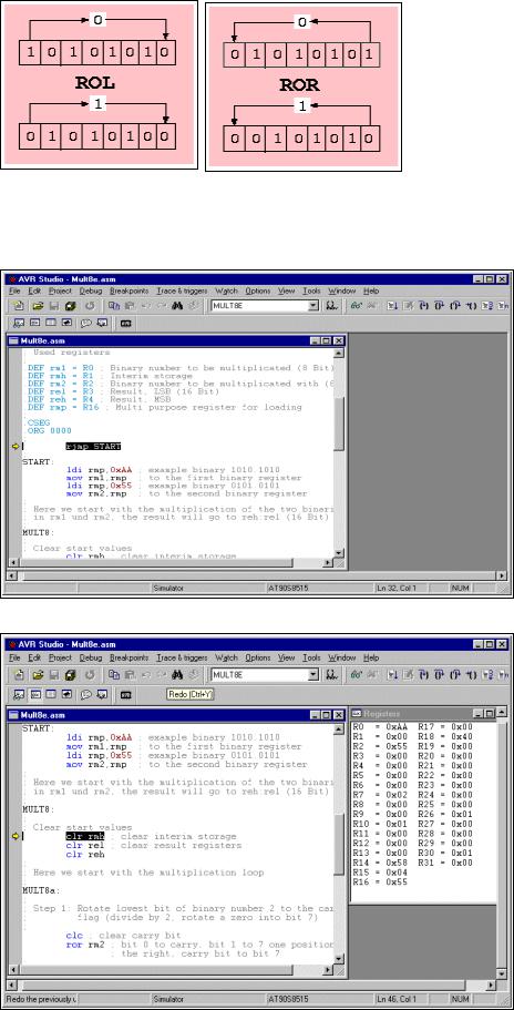
For understanding the multiplication operation, it is necessary to understand the binary rotation commands ROL and ROR. These instructions shift all bits of a register one position left (ROL) resp. right (ROR). The void position in the register is filled with the content of the carry bit of the status register, the bit that rolls out of the register is shifted to the carry bit. This operation is demonstrated using 0xAA as an example for ROL and 0x55 as an example for ROR.
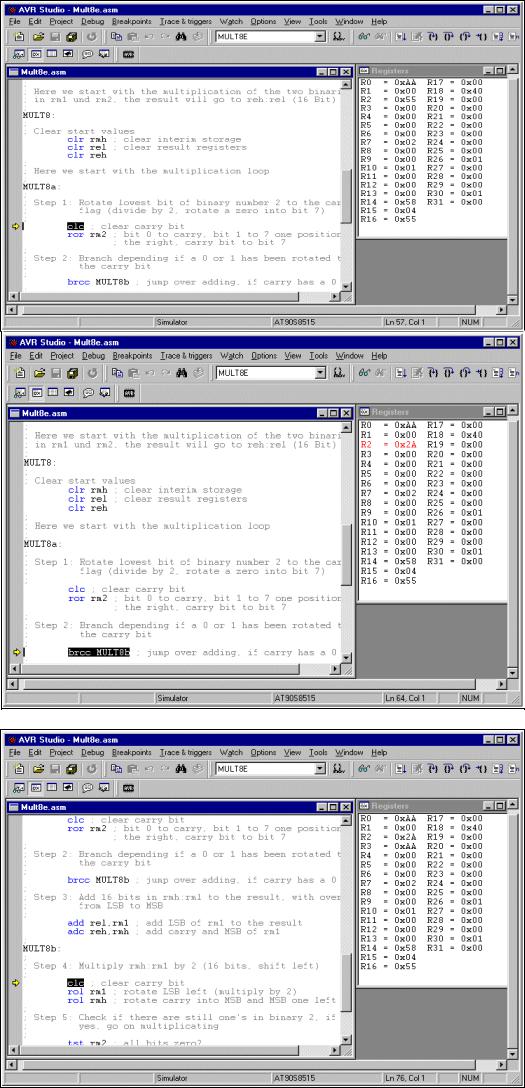
Multiplication in the studio
The following screenshots show the multiplication program in the simulator.
The object-code has been opened, the cursor is placed on the first executable instruction. F11 does single steps.
The registers R0 and R2 are set to 0xAA and 0x55, our test binaries, to be multiplied.
Avr-Asm-Tutorial |
33 |
http://www.avr-asm-tutorial.net |
|
|
|
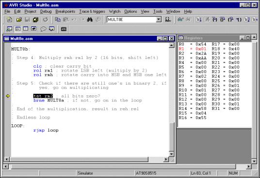
R2 is rotated to the right, to roll the least significant bit into the carry bit. 0x55 (0101.0101) yielded 0x2A (0010.1010).
Because the carry bit had a one the content of the registers R1:R0 is added to the (empty) register pair R4:R3, resulting in 0x00AA there.
Now the register pair R1:R0 is rotated one position left to multiply this binary by 2. From 0x00AA, multiplication by 2 yields 0x0154.
The whole multiplication loop is repeated as long there is at least one binary 1 in register R2. These following loops are not shown here.
Avr-Asm-Tutorial |
34 |
http://www.avr-asm-tutorial.net |
|
|
|
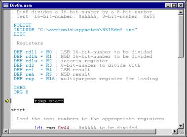
Using key F5 of the studio we multistepped over these loops to a breakpoint at the end of the multiplication routine. The result register pair R4:R3 has the result of the multiplication of 0xAA by 0x55: 0x3872.
This wasn't that complicated, just remind yourself on the similiar decimal operations. Binary multiplication is much easier than decimal.
Division
Decimal division
Again we start with the decimal division, to better understand the binary division. We assume a division of 5678 by 12. This is done like this:
|
|
|
|
5678 |
: 12 = ? |
-------------------------- |
|||||
- 4 |
* 1200 |
= 4800 |
|
||
|
|
|
|
---- |
|
|
|
|
|
878 |
|
- 7 |
* |
120 |
= |
840 |
|
|
|
|
|
--- |
|
|
|
|
|
38 |
|
- 3 |
* |
12 |
= |
36 |
|
|
|
|
|
-- |
|
|
|
|
|
2 |
|
Result: 5678 |
: 12 |
= 473 Remainder 2 |
|||
===================================
Binary division
In binary the multiplication of the second number (4 * 1200, etc.) is not necessary, due to the fact that we have only 0 and 1 as digits. Unfortunately binary numbers have much more single digits than their decimal equivalent, so transferring the decimal division to its binary equivalent is a little bit inconvenient. So the program works a bit different than that.
The division of a 16-bit binary number by a 8-bit binary in AVR assembler is listed in the following section.
;Div8 divides a 16-bit-number by a 8-bit-number (Test: 16-bit-number: 0xAAAA, 8-bit-number: 0x55)
.NOLIST
.INCLUDE "C:\avrtools\appnotes\8515def.inc"
.LIST
;Registers
.DEF rd1l = R0 ; LSB 16-bit-number to be divided
.DEF rd1h = R1 ; MSB 16-bit-number to be divided
.DEF rd1u = R2 ; interim register
.DEF rd2 = R3 ; 8-bit-number to divide with
.DEF rel = R4 ; LSB result
.DEF reh = R5 ; MSB result
.DEF rmp = R16; multipurpose register for loading
;
.CSEG
.ORG 0
rjmp start
Avr-Asm-Tutorial |
35 |
http://www.avr-asm-tutorial.net |
|
|
|
start:
;Load the test numbers to the appropriate registers ldi rmp,0xAA ; 0xAAAA to be divided
mov rd1h,rmp mov rd1l,rmp
ldi rmp,0x55 ; 0x55 to be divided with mov rd2,rmp
;Divide rd1h:rd1l by rd2
div8:
clr rd1u ; clear interim register
clr reh |
; clear result (the result registers |
clr rel |
; are also used to count to 16 for the |
inc rel |
; division steps, is set to 1 at start) |
; Here the division loop starts |
|
div8a: |
|
clc |
; clear carry-bit |
rol rd1l ; rotate the next-upper bit of the number |
|
rol rd1h ; to the interim register (multiply by 2) |
|
rol rd1u |
|
brcs div8b ; a one has rolled left, so subtract cp rd1u,rd2 ; Division result 1 or 0?
brcs div8c |
; jump over subtraction, if smaller |
|
div8b: |
|
|
sub rd1u,rd2; subtract number to divide with |
||
sec |
; set carry-bit, result is a 1 |
|
rjmp div8d |
; jump to shift of the result bit |
|
div8c: |
|
|
clc |
; clear carry-bit, resulting bit is a 0 |
|
div8d: |
|
|
rol rel |
; rotate carry-bit into result registers |
|
rol reh |
|
|
brcc div8a |
; as long as zero rotate out of the result registers: go on with the division loop |
|
; End of the division reached |
||
stop: |
|
|
rjmp stop |
; endless loop |
|
Program steps during division
During execution of the program the following steps are ran:
•Definition and preset of the registers with the test binaries,
•presetting the interim register and the result register pair (the result registers are presetted to 0x0001! After 16 rotations the rolling out of the one stops further division steps.),
•the 16-bit-binary in rd1h:rd1l is rotated bitwise to the interim register rd1u (multiplication by 2), if a 1 is rotated out of rd1u, the program branches to the subtraction step in step 4 immediately,
•the content of the interim register is compared with the 8-bit binarly in rd2, if rd2 is smaller it is subtracted from the interim register and the carry-bit is set to one, if rd2 is greater the subtraction is skipped and a zero is set to the carry flag,
•the content of the carry flag is rotated into the result register reh:rel from the right,
•if a zero rotated out of the result register, we have to repeat the division loop, if it was a one the division is completed.
If you don't understand rotation yet you'll find this operation discussed in the multiplication section.
Division in the simulator
The following screen shots demonstrate the program steps in the studio. To do this, you have to assemble the source code and open the resulting object file in the studio.
The object code has been started, the cursor is on the first executable instruction. The key F11 performs single steps.
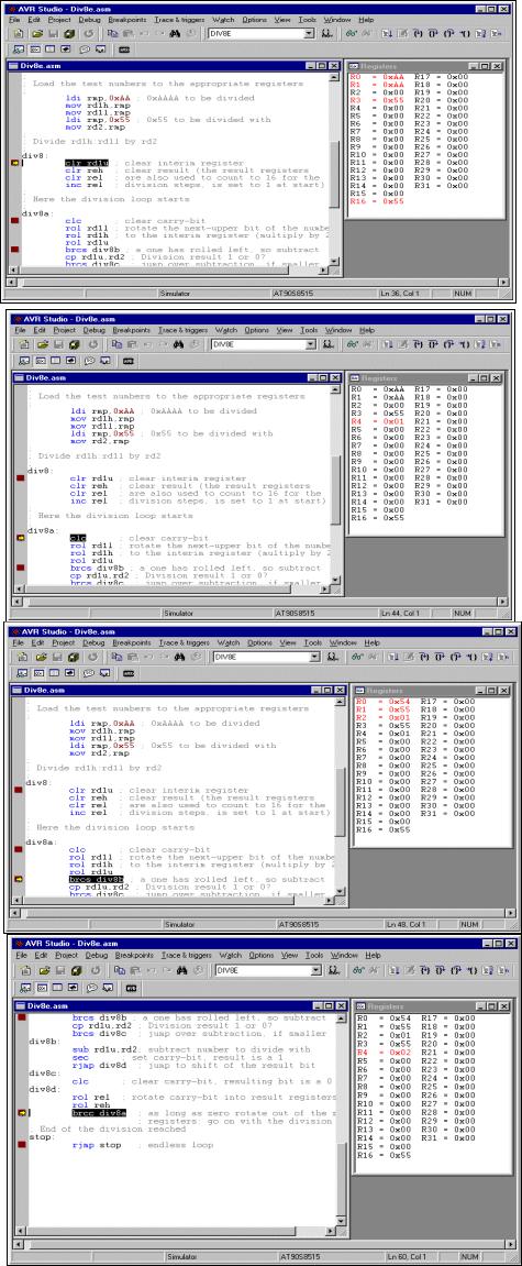
Avr-Asm-Tutorial |
36 |
http://www.avr-asm-tutorial.net |
|
|
|
The test binaries 0xAAAA and 0x55, to be divided, are written to the registers R1:R0 and R3.
The interim register R2 and the result register pair are set to their predfined values.
R1:R0 was rotated left to R2, from 0xAAAA the doubled value of 0x015554 was yielded.
No overflow from rotation into carry has occurred and 0x01 in R2 was smaller than 0x55 in R3, so subtraction was skipped. A zero in the carry is rotated into the result register R5:R4. The former content of the result register, a single 1-bit in position 0 has rotated to position 1 (content now: 0x0002). As a zero was rotated out of the result register pair, the next step to be executed is a branch to the beginning of the division loop start and the loop is repeated.