Advanced Robotics with the Toddler (Paralax, student guide, v1.3, 2004)
.pdf
Chapter #5: Following Light · Page 109
FOR Pulses = CurrentTilt TO NewValue STEP TiltStep
PULSOUT TiltServo, Pulses
PULSOUT StrideServo, CurrentStride
PAUSE MoveDelay
NEXT
CurrentTilt = NewValue
RETURN
StrideLeft:
NewValue = LeftStride
GOTO MovementStride
StrideCenter:
NewValue = CenterStride
GOTO MovementStride
StrideRight:
NewValue = RightStride
MovementStride:
FOR Pulses = CurrentStride TO NewValue STEP StrideStep
PULSOUT TiltServo, CurrentTilt
PULSOUT StrideServo, Pulses
PAUSE MoveDelay
NEXT
CurrentStride = NewValue
RETURN
' ----- Move feet to initial center position -----
ResetCC:
CurrentTilt = CenterTilt
CurrentStride = CenterStride
FOR Pulses = 1 TO 100 STEP StrideStep
PULSOUT TiltServo, CenterTilt
PULSOUT StrideServo, CenterStride
PAUSE MoveDelay
NEXT
DoReturn:
RETURN
Page 110 · Advanced Robotics with the Toddler
How the Light Follower Program Works
As in the previous program, the first IF...THEN statement tests for a difference in RC time measurements within the deadband. This statement has been modified so that it skips the walk_forward routine if the difference between RC times falls outside the deadband. On the other hand, if the difference in RC times is within the deadband, the forward pulse is executed. After the forward pulse, the program is directed back to main and the RC times are checked again.
IF ABS(LPhotoVal-RPhotoVal) > DeadBand THEN check_dir
walk_forward: Mx = Forward
GOSUB Movement goto main
If the difference between RC times is not within the DeadBand, the program skips to the Check_dir label. The IF...THEN statements following the Check_dir label are used to decide whether Toddler should turn left or turn right depending on the inequality of the
RPhotoVal and LPhotoVal values.
check_dir:
IF LPhotoVal > RPhotoVal THEN turn_right IF LPhotoVal < RPhotoVal THEN turn_left

Chapter #5: Following Light · Page 111
CHALLENGES
Lead your Toddler around with a flashlight.
√Instead of pointing the photoresistors at the surface directly in front of the Toddler, point them upward and outward. With the photoresistors adjusted this way, the Toddler will roam on the floor and try to always find the brightest place.
√Depending on the luminance gradient, you may have to increase the deadband to smooth out the Toddler’s light roaming. Alternatively, the deadband may need to be decreased to make it more responsive to seeking out the brighter areas.

Chapter #6: Object Avoidance with Infrared · Page 113
Chapter #6: Object Avoidance with Infrared
WIRELESS OBJECT DETECTION
Today's hottest products seem to have one thing in common: wireless communication. Personal organizers beam data into desktop computers, and wireless remotes let us channel surf. With a few inexpensive and widely available parts, the BASIC Stamp can also use an infrared LED and detector to detect objects to the front and side of your traveling Toddler.
Infrared means Infra means below, so Infra-red is light (or electromagnetic radiation) that has lower frequency, or longer wavelength than red light. Our IR LED and detector work at 980 nm. (nanometers) which is considered near infrared. Night-vision goggles and IR temperature sensing use far infrared wavelengths of 2000-10,000 nm., depending on the application.
Color |
Approximate Wavelength (nm) |
Violet |
400 |
Blue |
470 |
Green |
565 |
Yellow |
590 |
Orange |
630 |
Red |
780 |
Near infra-red |
800-1,000 |
Infra-red |
1,000-2,000 |
Far infra-red |
2,000-10,000 |
|
|
Detecting obstacles doesn’t require anything as sophisticated as machine vision. A much simpler system will suffice. Some robots use RADAR or SONAR (sometimes called SODAR when used in air instead of water). An even simpler system is to use infrared light to illuminate the robot’s path and determine when the light reflects off an object. Thanks to the proliferation of infrared (IR) remote controls, IR illuminators and detectors are easily available and inexpensive.
The Toddler infrared object detection scheme has a variety of uses. The Toddler can use infrared to detect objects without bumping into them. As with the photoresistors, infrared can be used to detect the difference between black and white for line following. Infrared can also be used to determine the distance of an object from the Toddler. The Toddler can use this information to follow objects at a fixed distance, or detect and avoid high ledges.
Page 114 · Advanced Robotics with the Toddler
Infrared Headlights for Toddler
The infrared object detection system we’ll build on the Toddler is like a car’s headlights in several respects. When the light from a car’s headlights reflects off obstacles, your eyes detect the obstacles and your brain processes them and makes your body guide the car accordingly. The Toddler uses infrared LEDs for headlights. They emit infrared, and in most cases, the infrared reflects off objects, and bounces back in the direction of the Toddler. The eyes of the Toddler are the infrared detectors. The infrared detectors send signals to the BASIC Stamp indicating whether or not they detect infrared reflected off an object. The brain of the Toddler, the BASIC Stamp, makes decisions and operates the servo motors based on this input.
The IR detectors have built-in optical filters that allow very little light except the 980 nm infrared that we want to detect onto its internal photodiode sensor. The infrared detector also has an electronic filter that only allows signals around 38.5 kHz to pass through. In other words, the detector is only looking for infrared flashed on and off at 38,500 times per second. This prevents interference from common IR interference sources such as sunlight and indoor lighting. Sunlight is DC interference (0 Hz), and house lighting tends to flash on and off at either 100 or 120 Hz, depending on the main power source in the country where you reside. Since 120 Hz is way outside the electronic filter’s 38.5 kHz band pass frequency, it is, for all practical purposes, completely ignored by the IR detectors.

Chapter #6: Object Avoidance with Infrared · Page 115
The FREQOUT Trick
Since the IR detectors only see IR signals in the neighborhood of 38.5 kHz, the IR LEDs have to be flashed on and off at that frequency. A 555 timer can be used for this purpose, but the 555 timer circuit is more complex and less functional than the circuit we will use in this and the next chapter. For example, the method of IR detection introduced here can be used for distance detection; whereas, the 555 timer would need additional hardware to do distance detection.
A pair of Toddler enthusiasts found an interesting trick that made the 555 timer scheme unnecessary. This scheme uses the FREQOUT command without the RC filter that’s normally used to smooth the signal into a sine-wave. Even though the highest frequency FREQOUT is designed to transmit is 32768 Hz, the unfiltered FREQOUT output contains a harmonic with useful properties for a 38.5 kHz IR detector. More useful still is the fact that you can use a command such as FREQOUT Pin, Period, 38500 to send a 38.5 kHz harmonic that the IR detector will detect.
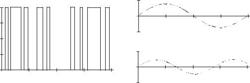
Figure 6-1 shows (a) the signal sent by the command FREQOUT Pin, Period, 27036. Tuned electronic receivers, such as the IR detectors we’ll be using, can detect components of this signal that are called harmonics. The FREQOUT signal’s two dominant low frequency harmonics are shown in (b) and (c). (b) shows the fundamental harmonic, and (c) shows the third harmonic. These harmonics are actually components of the unfiltered FREQOUT pulses shown in (a). The third harmonic shown in (c) can be controlled directly by entering commands such as
(instead of 27036) for 38.5 kHz, or FREQOUT Pin, Period, 40000 for 40 kHz, etc.

Page 116 · Advanced Robotics with the Toddler
Volts, V
+ 5
0
0Time, us
(a)Unfiltered freqout pulses sent by FREQOUT pin, period, 27036
Volts, V |
|
|
|
+ 1.25 |
|
|
|
0 |
|
|
|
- 1.25 |
0 |
Time, us |
3 |
(b) (b) 27036 Hz fundamental harmonic.
+ 1.25 |
|
|
|
0 |
|
|
|
37 |
|
|
|
- 1.25 |
0 |
Time, us |
3 |
(c) 38500 Hz third harmonic.
Figure 6-1: FREQOUT Example Properties
Even though the “FREQOUT” trick works, there is an additional problem. The BASIC Stamp does not multitask. The reason this is a problem is because the IR detector only sends the low signal indicating that it has detected an object while it is receiving the 38.5 kHz IR. Otherwise, it sends a high signal. Fortunately, it takes the detector long enough to rebound from its low output state that the BASIC Stamp can capture the value. The reason that the detector’s output takes so long to rebound is related to its tendency toward slower responses when it receives a signal with unequal high and low times, of which the signal in (a) has many.

Chapter #6: Object Avoidance with Infrared · Page 117
ACTIVITY #1: BUILDING AND TESTING THE NEW IR TRANSMITTER / DETECTOR
Parts Required
(1)Piezoelectric speaker
(2)Shrink wrapped IR LEDs
(2)IR detectors (misc) wires
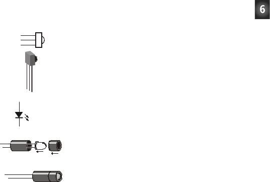
Figure 6-2 shows the individual part schematics and pictorials so you can identify them. Figure 6-3 is the schematic. Build this circuit on your Toddler board. Note that the 220 ohm resistors are already built into the Toddler PCB; just plug in the infrared LEDs and your Toddler will be ready.
1
2
3
1 2 3
1
IR
LED
2
Infrared detector schematic symbol
Infrared detector component
Figure 6-2:
Infrared Components and their Schematic Symbols
Infrared LED schematic symbol
IR LED will snap in.
IR LED component with light shield assembly
+ -

Page 118 · Advanced Robotics with the Toddler
P4 |
|
|
|
|
|
|
|
|
|
|
|
|
|
|
|
|
|
|
|
P15 |
|
|
|
|
|
|
|
|
|
|
|
|
|
|
|
|
|
|
||||||
|
|
|
|
|
|
|
|
|
|
|
|
|
|
|
|
|
|
|
|
|
|
|
|
|
|
|
||||||||||||||||||
|
|
|
|
|
|
|
|
220 Ω |
|
|
|
|
|
|
|
|
|
|
|
|
|
|
|
|
220 Ω |
|
|
|
|
|
|
|
|
|||||||||||
|
|
|
|
|
|
Vdd |
|
|
|
|
|
|
|
IR |
|
|
|
|
|
|
Vdd |
|
|
|
|
|
|
|
IR |
|||||||||||||||
|
|
|
|
|
|
|
|
|
|
|
|
|
|
|
|
|
|
|
|
|
|
|
|
|
|
|
|
|
|
|
|
|
|
|
|
|
|
|
|
|
|
|
||
P11 |
|
|
|
|
|
|
|
|
|
|
|
|
|
|
|
|
|
|
|
|
LED |
P14 |
|
|
|
|
|
|
|
|
|
|
|
|
|
|
|
|
|
|
|
LED |
||
|
|
|
|
|
|
|
|
|
|
|
|
|
|
|
|
|
|
|
|
|
|
|
|
|
|
|
|
|
|
|
|
|
|
|
||||||||||
|
|
|
|
|
|
|
|
|
|
|
|
|
|
|
|
|
|
|
|
|
|
|
|
|
|
|
|
|
|
|
|
|
|
|
|
|
|
|
||||||
|
|
|
|
|
|
|
|
|
|
|
|
|
|
|
|
|
|
|
|
|
|
|
|
|
|
|
|
|
|
|
|
|
|
|
|
|
|
|
||||||
|
|
|
|
|
|
|
|
|
|
|
|
|
|
|
|
|
|
|
|
|
|
|
|
|
|
|
|
|
|
|
|
|
|
|
|
|
|
|
||||||
|
|
|
|
|
|
|
|
|
|
|
|
|
|
|
|
|
|
|
|
|
|
|
|
|
|
|
|
|
|
|
|
|
|
|
|
|
|
|||||||
|
|
|
|
|
|
|
|
|
|
|
|
|
|
|
|
|
|
|
|
|
|
|
|
|
|
|
|
|
|
|||||||||||||||
|
|
|
|
|
|
|
|
|
|
|
|
|
|
|
|
|
|
|
|
|
|
|
|
|
|
|
|
|
|
|
|
|||||||||||||
|
|
|
|
|
|
|
|
|
|
|
|
|
|
|
|
|
|
|
|
|
|
|
|
|
|
|
|
|
|
|
|
|
|
|
|
|
|
|
|
|
|
|
|
|
|
|
|
|
|
|
|
|
|
|
|
|
|
|
|
|
|
|
|
|
|
|
|
|
|
|
|
|
|
|
|
|
|
|
|
|
|
|
|
|
|
|
|||
|
|
|
|
|
|
|
|
|
|
|
|
|
|
|
|
|
|
|
|
|
|
|
|
|
|
|
|
|
|
|
|
|
|
|
|
|
|
|
|
|
|
|||
|
|
|
|
|
|
Vss |
Vss |
|
|
|
|
|
|
|
Vss |
Vss |
||||||||||||||||||||||||||||
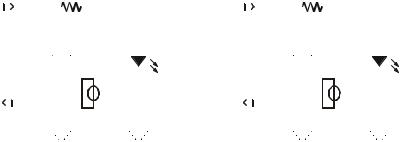
Figure 6-3: Infrared circuit schematic Note: the 220 ohm resistors are already built into the Toddler PCB and are not required; simply plug the LEDs into the front sockets.
One IR pair (IR LED and detector) is mounted on each corner of the Toddler circuit board.
Testing the IR Pairs
The key to making each IR pair work is to send 1 ms of unfiltered 38.5 kHz FREQOUT harmonic followed immediately by testing the signal sent by the IR detector and saving its output value. The IR detector’s normal output state when it sees no IR signal is high. When the IR detector sees the 38500 Hz harmonic sent by the IR LED, its output will drop from high to low. Of course, if the IR does not reflect off an object, the IR detector’s output simply stays high. Program 6.1 shows an example of this method of reading the detectors.
