

ISO/IEC 19501:2005(E)
Atool must enforce the correspondence to built-in attributes.
5.18Stereotypes
5.18.1 Semantics
A stereotype is, in effect, a new class of metamodel element that is introduced at modeling time. It represents a subclass of an existing metamodel element with the same form (attributes and relationships) but with a different intent. Generally a stereotype represents a usage distinction. A stereotyped element may have additional constraints on it from the base metamodel class. It may also have required tagged values that add information needed by elements with the stereotype. It is expected that code generators and other tools will treat stereotyped elements specially. Stereotypes represent one of the built-in extensibility mechanisms of UML.
5.18.2 Notation
The general presentation of a stereotype is to use the symbol for the metamodel base element but to place a keyword string above the name of the element (if any). The keyword string (Section 5.9, “Keywords,” on page 181) is the name of the stereotype within matched guillemets, which are the quotation mark symbols used in French and certain other languages (for example, «foo»).
NOTE: A guillemet looks like a double angle-bracket, but it is a single character in most extended fonts. Most computers have a Character Map utility. Double angle-brackets may be used as a substitute by the typographically challenged.
The keyword string is generally placed above or in front of the name of the model element being described. If multiple stereotypes are defined for the same model element, they are placed vertically one below the other. The keyword string may also be used as an element in a list, in which case it applies to subsequent list elements until another stereotype string replaces it, or an empty stereotype string («») nullifies it. Note that a stereotype name should not be identical to a predefined keyword applicable to the same element type.
To permit limited graphical extension of the UML notation as well, a graphic icon or a graphic marker (such as texture or color) can be associated with a stereotype. The UML does not specify the form of the graphic specification, but many bitmap and stroked formats exist (and their portability is a difficult problem). The icon can be used in one of two ways:
1.It may be used instead of, or in addition to, the stereotype keyword string as part of the symbol for the base model element that the stereotype is based on. For example, in a class rectangle it is placed in the upper right corner of the name compartment. In this form, the normal contents of the item can be seen.
2.The entire base model element symbol may be “collapsed” into an icon containing the element name or with the name above or below the icon. Other information contained by the base model element symbol is suppressed. More general forms of icon specification and substitution are conceivable, but we leave these to the ingenuity of tool builders, with the warning that excessive use of extensibility capabilities may lead to loss of portability among tools.
If multiple stereotypes are defined, the graphical icons or markers are omitted.
UML avoids the use of graphic markers, such as color, that present challenges for certain persons (the color blind) and for important kinds of equipment (such as printers, copiers, and fax machines). None of the UML symbols require the use of such graphic markers. Users may use graphic markers freely in their personal work for their own purposes (such as for highlighting within a tool) but should be aware of their limitations for interchange and be prepared to use the canonical forms when necessary.
The classification hierarchy of the stereotypes themselves can be displayed on a class diagram, as described in Section 5.35, “Stereotype Declaration,” on page 220. This capability is not required by many modelers who must use existing stereotypes but not define new kinds of stereotypes.
♥ ISO/IEC 2005 - All rights reserved |
199 |
ISO/IEC 19501:2005(E)
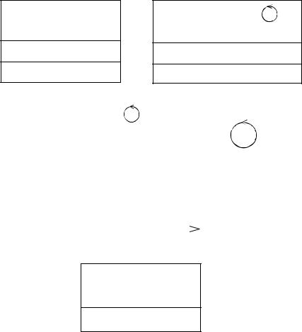
5.18.3 Examples
Figure 54 illustrates various notational forms of the stereotype notation. Note that the top four shapes are alternatives of each other. The next one shows how a dependency can be stereotyped and the bottom example illustrates a model element with multiple stereotypes.
«control»
PenTracker
location: Point
enable (Mode)
«control»
PenTracker
location: Point
enable (Mode)
PenTracker |
|
|
|
|
|
location: Point |
|
|
|
PenTracker |
|
enable (Mode) |
||
|
||
|
|
JobManager |
|
|
|
|
|
|
«call» |
Scheduler |
||||||||||
|
|
|
|
|
|
|
|
|
|
|
|
|
|
|
|
|
||
|
|
|
|
|
|
|
|
|
|
|
|
|
|
|
|
|
||
|
|
|
|
|
|
|
|
|
|
|
|
|
|
|
|
|
|
|
«control»
«semaphore»
Lock
reqQueue: Queue
Figure 54 - Varieties of Stereotype Notation
5.18.4 Mapping
The use of a stereotype keyword maps into the stereotype relationship between the Element corresponding to the symbol containing the name and the Stereotype of the given name. The use of a stereotype icon within a symbol maps into the stereotype relationship between the Element corresponding to the symbol containing the icon and the Stereotype represented by the symbol. A tool must establish the connection when the symbol is created and there is no requirement that an icon represent uniquely one stereotype. The use of a stereotype icon, instead of a symbol, must be created in a context in which a tool implies a corresponding model element and a Stereotype represented by the icon. The element and the stereotype have the stereotype relationship.
200 |
♥ ISO/IEC 2005 - All rights reserved |