

stud / user-manual-METEX-MS-9160-E
.PDFf)OFFSET adjustment
-The DC voltage level of the output signal can be adjusted with the OFFSET control knob in the range of +/- 10 V.
-To set the DC voltage level, pull this control knob out. Turning to the right means positive voltage, turning to the left means negative voltage.
-If the control knob is pressed, the output voltage will have no DC voltage component.
g)Symmetry adjustment
-The symmetry of the output voltage can be changed in the range of 1:3 and 3:1.
The control knob carries the designation SYM.
-To change the symmetry of the waveforms, pull the SYM control knob and turn it slowly to the left (ccw) or to the right (cw). Refer to the table for the resulting waveforms.
BASIC WAVEFORMS |
CLOCK WISE (CW) |
COUNTER CLOCKWISE (CCW) |
SINE |
SKEWED SINE |
SKEWED SINE |
SQUARE |
PULSE |
PULSE |
TRIANGLE |
SAWTOOTH |
SAWTOOTH |
Note!
Note that because of this adjustment of symmetry, the frequency can change and therefore should be readjusted.
h)SWEEP adjustment (Wobbler)
-To operate the built-in frequency sweep, pull the SWEEP WIDTH control knob and use it to adjust the width of the sweep signals in the range 100 : 1.
-To achieve maximum width, turn the frequency adjustment knob (with scale) to its left stop and the width control to its right stop.
-To adjust the speed of the sweep signal, turn the SWEEP RATE control knob slowly to the left or right. A linear sweep signal is obtained.
-A logarithmic sweep signal is possible by pulling the SWEEP RATE control knob.
i)TTL output
-The TTL level is available at the TTL OUT socket (BNC).
A TTL level is an "asymmetric square wave". It is asymmetrical because, in contrast to the sine or "pure" square waves, the signal does not cross zero, i.e. it has no negative voltage values (negative logic excepted).
-The TTL output can drive 20 "unit loads" when HIGH and 15 "unit loads" when LOW.
-One "unit load" is 40 µA for the HIGH and 1.6 mA for the LOW state.
j)Output impedance
-The output impedance of the generator output F/G OUT, is 50 Ohm or 600 Ohm depending on the setting of the 50 / 600 Ohm switch.
20 |
21 |
5.3 The DC voltage measuring instrument
|
|
|
|
|
|
|
|
|
|
|
|
|
|
|
|
|
|
|
|
|
|
|
|
|
|
|
|
|
|
|
|
|
|
|
|
|
|
|
|
|
|
|
|
|
|
|
|
|
|
|
|
|
|
|
|
|
|
|
|
|
|
|
|
|
|
|
|
|
|
|
|
|
|
|
|
|
|
|
|
|
|
|
|
|
|
|
|
|
|
|
|
|
|
|
|
|
|
|
|
|
|
|
|
|
|
|
|
|
|
|
|
|
|
|
|
|
|
|
|
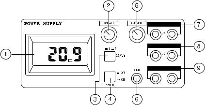
Operating elements |
|
|
|
|
|
|
|
|
|
|
|
|
|
|
|
|
|||
|
|
|
|
|
|
|
|
|
|
|
|
|
|
|
|
||||
|
|
|
|
|
|
|
|
|
|
|
|
|
|
|
|
||||
|
|
|
|
|
|
|
|
|
|
|
|
|
|
|
|
||||
|
|
|
|
|
|
|
|
|
|
|
|
|
|
|
|
||||
|
|
|
|
|
|
|
|
|
|
|
|
|
|
|
|
||||
|
|
|
|
|
|
|
|
|
|
|
|
|
|
|
|
||||
|
|
|
|
|
|
|
|
|
|
|
|
|
|
|
|
||||
1. |
Illuminated 3 1/2-position |
5. |
Adjustable current limiting |
||||||||||||||||
|
17 mm high LCD display |
6. |
Ground connector |
||||||||||||||||
2. |
Voltage adjustment |
7. |
Fixed voltage output 5 V / 2 A |
||||||||||||||||
3. |
V/A display switch |
8. |
Fixed voltage output 15 V / 1 A |
||||||||||||||||
4. |
AC power main switch |
9. |
Adjustable output 0-30 V / 0-3 A |
||||||||||||||||
Attention! Safety measures!
Protect the instrument from being dropped and from external mechanical damage by falling objects.
Do not short circuit the "+" and "-" terminals.
Never go beneath the maximum permitted load of 2.5 Ohm at the 5V/2A output and 15 Ohm at the 15V/1A output.
Basic settings
a)Before connecting the AC power cable, ensure that no load is present on the output terminals of the power supply.
b)Centralise the (CURRENT) current-limiting control knob.
c)Switch the AC power switch (POWER) on.
d)The LEDs under the legends 5 V and 15 V light up.
e)Connect the loads to the 5V and 15V output.
f)Switch the display switch to "V" (voltage) and set the desired output voltage.
g)Now connect the load to the output terminals "+" and "-" of the adjustable output. While doing this, observe the polarity of the load.
Attention!
All outputs are floating. Other outputs can either be grounded through the ground socket (= chassis) on the front panel (bottom right) or remain floating.
Current limiting characteristics
All 3 outputs are independently protected against overload and short circuit by means of a separate current limiting circuit.
a)Output 0 to 30 V, 3 A: protected by means of current limiting. If the output current increases due to a load of more than 3 A, the output voltage is reduced (with a short circuit to approx. 0.2 V).
b)Fixed voltage output 5 V / 2 A: protected by a fixed current limit (stabilising circuit).
Should the load current exceed the value of 2.2 A, the output voltage is reduced.
c)Fixed voltage output 15 V / 1 A: protected by a fixed current limit (stabilising circuit).
Should the load current exceed the value of 1.2 A, the output voltage is reduced.
22 |
23 |
5.4 The digital multimeter
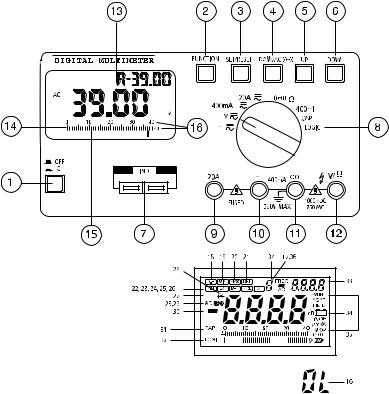
5.4.1 Operating elements
1.Device on/off
2.Function pushbutton
The various subfunctions, such as MIN/MAX, REL, DUAL, etc. are set using this button.
3.Set/Reset button
The instrument is reset into its basic condition with this button.
4.DC Ω / AC (•) button
This button switches the measurement from DC to AC values or, under resistance measurement, from actual resistance measurement to continuity test
5.Up button ("plus" button)
6.Down button ("minus" button)
7.Capacity and inductance socket
In this socket uncharged capacities and voltage-free inductances (coils, chokes, transformers, etc.) can be measured.
8.Rotary switch for setting the different operations (voltage measurement, current measurement, etc.)
9.A input socket for the measurement of DC and AC currents to 20 A max.
10.mA input:
This input is for measuring direct and alternating currents up to 400 mA max. (protected with a quick-acting 800mA fuse).
11.COM (-) input socket (COM or negative connection)
12.V-Ohm (+) input socket (= positive connection)
13.LCD display (3/4-position, highest display value: 3999)
14.Analogue bar graph
15.Bar graph line division
16.Overload "OL" display
If "OL" appears in the display, this means that the range has been exceeded
Attention!
Observe maximum input levels.
17.Auto Hold "A" in front of the small display
18.Data Hold
Data Hold "freezes" the measured value.
19.MIN = Minimum
As soon as this symbol appears in the display, the lowest-measured value at any given time is displayed, for example during discharge of rechargeable cells.
20.MAX = Maximum
As soon as this symbol appears in the display, the highest-measured value at any given time is displayed, e.g. during overvoltage.
21.REL = Relative
22.MEM = Memory
23.RCL = Recall = of stored measured value
24.R-H = Range Hold = Auto Range switched off, manual range{723} selection, excluding CAP capacity measuring range.
25.EXT = External
24 |
25 |
With this function, two different operating modes can be read simultaneously, e.g. the secondary voltage of a transformer < 125 VAC rms and AC power frequency
26.CMP = Comparison
27."  " = Inductance
28.AC = AC voltage or current
29.(•) = Symbol for acoustic continuity tester
30."-" = Minus sign and symbol for negative polarity
31.CAP = Capacity ==> measurement of capacitors
32.LOGI = Logic test
When the logic test function is selected, this symbol appears in the display
33.Second "small" display for the DUAL display function
34.= Battery symbol
If this symbol appears in the display, the battery must be changed.
35.Various measurement units
36.Reference number: indicating the memory location numbering for the MEM and RCL (=Recall) functions
5.4.2. Using the multimeter
A) Fitting the battery - changing the battery
So that the measuring instrument functions perfectly, it must be fitted with a 9V battery. When the battery change symbol appears in the display (after approx. 60 hours of operation) the battery must be replaced. To do this, proceed as follows:
The battery compartment is located beneath the upper cover (on the rear of the case) which is secured with two screws, left and right.
Attention!
Remove the MS-9160 without fail from all circuits being measured before changing the battery.
Always switch off the instrument with the main switch (POWER), which is located in the control area of the DC voltage power supply.
Only when it is certain that the MS-9150 is disconnected from AC
power and from all circuits should changing the battery be begun. Screw out both crosshead screws carefully with a suitable screwdriver and remove the cover cautiously. Remove the used battery (9 V). It is connected with a battery clip. Remove this carefully from the old battery and connect the clip to a fresh, unused battery observing the polarity. Push the battery into the battery compartment to the stop and screw the cover carefully up again.
Attention!
Do not under any circumstances operate the measuring instrument when it is open! Danger to life!
Leave no used battery in the measuring instrument, because even leakproof batteries can corrode and thereby release chemicals, which can endanger health and destroy the battery compartment. Used batteries are to be considered as special waste and must therefore be disposed of without putting the environment at risk. Special collection containers are provided for this purpose by specialist dealers and in scrap yards.
Switch the measuring instrument off when it is no longer required.
B) Connecting the test leads
Always use only the supplied test leads for making measurements. Before each connection note the condition of the connecting plug and test probes and check the insulation for damage.
These test leads are intended for voltages up to 1000 V max. The measuring instrument is similarly designed for voltages up to 1000 VDC and 750 VAC rms max. Take particular care when dealing with voltages greater than 25 V AC or 35 V DC.
Attention!
Never exceed the maximum input amplitudes, because danger to life can arise under adverse conditions.
C) Putting into service
C.1 Basic settings
Press the ON button (1). The display is now illuminated. To select a function, rotate the operating mode switch to the desired position. "Normal" measurements can now be performed without additional func-
26 |
27 |
tions.
To select such an additional function, press the FUNCTION (2) button. By the repeated pressing of this button the various subfunctions are displayed in the display. To exit from the menu, press the Set/Reset button twice: once sets the subfunction, twice resets it.
C.2 Button configuration
a)The ON/OFF button switches the measuring instrument both on and off: if the button is pressed once, the instrument is switched on; if it is pressed a second time, it is switched off.
After approx. 8 minutes of "zero use", when the display hardly changes (with open test leads), the Auto Power Off function switches the multimeter off, to save energy. The multimeter must then be switched off and on again.
b)FUNCTION
The A-H symbol appears in the display as soon as the instrument is switched on. Press the "FUNCTION" button to call the subfunctions. The following symbols appear in the display as a result: D-H -> MIN -> MAX -> REL -> CMP -> R-{783}H -> EXT -> MEM -> RCL
c)Set/Reset
To activate, i.e. switch on, a selected subfunction, press this button once.
Press the button once to return to the basic setting again (Reset).
d)DC/Ohm/AC (•)
When the operating mode switch is set to voltage or current measurement, press this button to switch from DC voltage measurement to AC voltage measurement. When the measurement function switch is set to (•), this button must also be pressed to switch from acoustic continuity test to resistance measurement.
e)UP / DOWN
Press one of these buttons to set the reference value in the REL or CMP subfunctions and to address the stored value in the MEM or RCL (Recall Memory) subfunctions.
C.3 Connector and socket configuration
a)Sockets for capacity or inductance measurement
Insert the (discharged!) capacitor observing polarity or the voltagefree inductance (coil) into the sockets. Ensure that the connections are long enough, because otherwise incorrect measurements can
occur.
b) Operating mode switch = measurement function switch (8)
Attention!
The operating mode switch may not be moved during measurements, because otherwise the measuring instrument can be destroyed and as a result danger to life can occur.
Arranged in a semi-circle, the various basic measurement ranges selectable by rotating the switch are:
mV |
= millivolt AC/DC (milli = 10 exp.-3) |
|
V |
= |
Volt AC/DC |
400mA |
= |
milliampere AC/DC |
20A |
= |
Ampere AC/DC |
(@)= Continuity test
W |
= |
Resistance measurement |
mH |
= |
Inductance measurement |
CAP |
= |
Capacity measurement |
LOGIC |
= |
Logic test |
c)20 A socket
For DC or AC current measurements up to 20 A max.(!), the red test lead must be plugged in here.
Attention!
When measuring current,the operating mode switch must never be set to voltage (mV or V) or to any other switch position other than current measurement (mA or A).
d)mA socket
The red test lead must be plugged in here for DC or AC current measurements to 400 mA max!, but only when the operating mode switch is set to "400mA".
e)COM = common socket
Except for capacity and inductance measurements, the black test lead must be plugged in here for all measurements (common socket means minus, "-" or ground socket)
f)V/Ohm socket
28 |
29 |
The red test lead must be plugged into this socket when voltage or resistance measurements, continuity check or logic tests are performed.
C.4 Explanation of display and symbols
a)Digital display
The display can show up to "3999" and the polarity (-) is automatically displayed (for negative voltages and reversed polarity). Additionally there are three decimal point positions.
b)Analogue bar graph
The analogue bar graph consists of 43 segments. It has a higher speed of measurement than the digital display. Measured value trends are thus more easily recognised. If the measurement range is exceeded, "OL", for Overload will be displayed and the display "flashes" in warning.
c)Auto Hold and Dual Display "d"
The Auto Hold function is active for DC voltage, current, resistance, and capacity (CAP) measurements and continuity test. The measured value, visible in the "large" display 4 - 5 sec. beforehand, is displayed in the small display. The Auto Hold function itself is indicated with the letter "A" in front of the small display. "d" for Dual Display appears left in front of the small display, when an AC voltage (ACV) or logic (LOGIC) measurement is carried out. The following table shows which measurements / indications are possible:
Measuring function |
|
Main display |
|
Subdisplay |
|
|
|||
|
|
(Large display) |
|
(Small display) |
|
|
|
|
|
AC voltage |
|
AC voltage |
|
dB(m) |
Logic measurement |
|
Hi/Lo |
|
DC voltage |
|
|
|
|
|
d)Data-Hold "D-H"
With D-H a measured value is frozen (held).
e)MIN (= Minimum)
Press this button once: the smallest measured value is displayed on the second-(DUAL)display, while measurements continue with the "normal" display.
f)MAX (= Maximum)
Press the Set/Reset button once: the highest measured value is now displayed on the second display, while measurements continue with the large display.
g)REL (= Relative)
This setting permits the comparison of a reference value with a subsequent measured value. Proceed as follows:
1.First press the "Function" button until "REL" appears in the display.
2.Now set the polarity of the reference value, the reference value and the measurement range with the "UP" and "DOWN" buttons. After each input the SET/RESET button must be pressed once in confirmation.
Button operation sequence: |
|
|
=> Function => Display "REL" => |
|
|
=> Setting ± (with UP-/DOWN buttons) |
=> SET/RESET |
=> |
=> Setting first position |
=> SET/RESET |
=> |
=> Setting 2nd position |
=> SET/RESET |
=> |
=> Setting 3rd position |
=> SET/RESET |
=> |
=> Setting 4th position |
=> SET/RESET |
=> |
=> Setting the measurement range (no automatic range change) => SET/RESET =>
=> The small display displays the reference value
The measuring instrument will now show the difference between the stored value and the subsequently-measured value on the small display, while the actual value presently being measured can be read on the large display.
Example:The reference value is 100.0 V; the present (large display) reading shows 90 V. On the small display the difference of -10 V can be read. Should the next measured value be 100.0 V, the differ. will be "0". The small display then reads 0000. The display can display 3999 max.
Attention!
With the REL function, RESET using the SET/RESET button is not possible. To exit this function, press either the measurement function switch or the FUNCTION button or one of the other buttons.
30 |
31 |
h)MEM (= Memory)
With this special function up to 8 reference values can be stored, except under temperature measurement. For this, proceed as follo-
ws:
1.Press the function button until MEM appears in the display,
2.Press the UP/DOWN button, to set a reference number between 0 and 4,
3.Press the Set/Reset button, to store the value.
When several reference values are "filed" under the same reference number, the previous value will be overwritten in each case.
i)RCL (= Memory Recall)
This function reads the stored reference value from the memory.
Proceed as follows:
1.Press the UP or DOWN button to select the desired reference number,
2.Now press the Set/Reset button to read out the stored value. The
read-out value is shown on the small display.
k)R-H = Range Hold
With this function it is possible to exit the Auto Range mode and to set/determine the measurement range in the selected operating mode (voltage, current, resistance, etc. measurement) by pressing the UP and DOWN buttons manually. This function is not available while measuring capacity (CAP).
l)EXT (= External)
With this function two different operating modes can be read simultaneously, one on the large display, one on the small display. Note the following table in this connection:
Operation mode |
|
Main display |
|
Subdisplay |
|
|
|||
|
|
|
|
|
AC voltage |
|
AC voltage |
|
Frequency change-over |
Logic measurement |
|
Hi/Lo |
|
Frequency change-over |
|
|
|
|
|
m)CMP (= Comparison)
In this subfunction a high/low comparison can be made, in which the highest and lowest stored reference values can be compared with the presently-measured value. To exit from this function, briefly press the operating mode switch. First set the desired measurement range. Then proceed according to the following examples:
Button operation sequence
=> FUNCTION |
=> display "CMP" and "MIN" => |
|
=> set polarity +/- (Up/Down) |
=> SET/RESET |
=> |
=> set 1st position |
=> SET/RESET |
=> |
=> set 2nd position |
=> SET/RESET |
=> |
=> set 3rd position |
=> SET/RESET |
=> |
=> set 4th position |
=> SET/RESET => |
|
=> display "CMP" and "MAX" |
=> |
|
=> set +/- |
=> SET/RESET => |
|
=> set 1st position |
=> SET/RESET => |
|
=> set 2nd position |
=> SET/RESET => |
|
=> set 3rd position |
=> SET/RESET => |
|
=> set 4th position |
=> SET/RESET => |
|
=> display of "CMP", "MIN" or "MAX" and "LO" or "HI" or "PASS" in the small display
=> the instrument is ready for comparison measurement.
Note!
With the High/Low logic function the CMP function is inoperable.
n)Display for the reference number
The reference number is applicable to the MEM and RCL functions. The numbers are called by pressing the UP (+1) or DOWN (-1) buttons.
C.5 Display information and symbols about operating modes
a)" " Inductance measurement
The measurement range covers from 0.01 mH to 400 mH max.
b)(•) Continuity test
The continuity of voltage-free wiring, plug connections or fuses can be checked with this function acoustically and optically (display of measured value).
c)"-" Negative polarity
With reversed test leads and with negative polarity, a "-" sign appears in front of the measured value.
d)CAP Capacity measurement
The capacity measurement range enables measurements of discharged capacitors from 4 nF to 400 µF
e)LOGIC logic test
All logic levels can be measured and displayed with this function.
f)Battery change indicator
An alkaline 9 V battery has an average life of approx. 60 hours in this measuring instrument. About 8 hours before the battery end of
32 |
33 |
life, the battery change symbol appears in the display.
A battery check is carried out each time between individual measurement cycles.
g) all other symbols, which stand for the various measurement units:
AC |
= |
AC units |
DC |
= |
DC units |
mV |
= |
millivolt (exp.-3) |
V |
= |
Volt |
mA |
= |
milliampere (exp.-3) |
A |
= |
Ampere |
kHz |
= |
kilohertz (exp.3) |
uF |
= |
microfarad (exp.-6) |
nF |
= |
nanofarad (exp.-9) |
mH |
= |
milliHenry (exp.-3) |
uH |
= |
mikroHenry (exp.-6) |
W |
= |
Ohm |
kW |
= |
kiloohm (exp.3) |
MW |
= |
Megaohm (exp.6) |
5.4.3 Performing measurements A) Voltage measurement
Attention!
Under no circumstances exceed the maximum permitted input amplitude. 1000 VDC max. and 750 VAC rms max.
Touch no circuits or components when voltages greater than 25 VAC rms or 35 VDC are present.
To measure DC or AC voltages, proceed as follows:
1.Set the rotary switch to the desired position (mV or V)
2.Connect the red test lead to the V/Ohm socket (+) and the black test lead to the COM socket (-)
3.Press the DC/AC button according to whether DC or AC voltage is to be measured. As soon as "AC" appears in the display, the AC voltage measurement range is set.
4.Connect the test probes to the points of measurement (load, circuit, etc.).
Each of the five voltage ranges, whether AC or DC, has an input impedance of 10 MOhm in parallel with 100 pF. The AC voltage input is ACcoupled. As soon as a "-"-sign appears in front of the measured value under DC voltage measurements, the measured voltage is negative (or the test leads reversed).
B) Current measurement
To measure direct or alternating currents, procedure is as follows:
1.Set the rotary switch to current measurement (400mA or 20A).
2.Connect the red test lead to the mA socket when currents up to 400 mA max. are to be measured and to the A socket for currents up to 20 A max.
3.Press the DC/AC button according to whether DC or AC current is now to be measured.
As soon as "AC" appears in the display, the AC current measurement range is set.
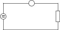
4.Connect the instrument leads in series with the test object (see figure below).
Attention!
Do not measure any currents in circuits in which voltages greater than 250 VDC or VAC rms can occur. Under no circumstances should currents over 20 A be measured. Measurements should only be made in 16Afused current circuits or those in which powers greater than 4000 VA cannot occur. Measurements of currents equal to 20 A must only be measured for a maximum of 30s duration and must only be performed at intervals of 15 minutes (cooling down phase for the shunt).
|
A DMM |
|
Current |
Consuming |
|
device, |
||
source |
||
load, circuit |
||
|
34 |
35 |
C) Continuity test
With this function voltage-free leads, fuses, circuits etc. can be acoustically checked for continuity. This measurement is performed as follows:
1.Position the rotary switch to (•).
2.Connect the red test lead to the V/Ohm socket (+) and the black test lead to the COM socket (-).
3.Then connect the test probes to the points of measurement.
Attention!
Measure no charged capacitors, because otherwise the measuring instrument can be destroyed by a possible discharge.
D) Resistance measurement
Attention!
Ensure that all components, circuits, chips and other objects to be measured, are completely voltage-free.
1.Set the measurement function switch to resistance measurement (OHM).
2.Connect the red test lead to the V/Ohm socket (+) and the black test lead to the COM socket (-).
3.Now connect the measuring probes with the test object.
The resistance of the test leads can normally be ignored (approx. 0.1 to 0.2 Ohm). However, this low value can lead to inaccuracies in the lowest measurement range.
Using the "REL" function, this resistance can be "subtracted" to compensate for these "measurement errors", i.e. the display referenced and set to "0".
When a resistance measurement is performed, ensure that the test points which you touch with the test probes during measurement are free from dirt, oil, solder flux or similar. Such conditions can falsify the measured value.
With resistances greater than approx. 4 MOhm the display can require some time to become stabilised.
As soon as "OL" appears in the display and the bar graph flashes, the measurement range has been exceeded and the measurement path is interrupted.
E) Inductance measurement
For the measurement of inductance proceed as follows:
1.Set the rotary switch to "400 mH".
2.Measurements can now be performed with the test socket on the measuring instrument. The "R-H" function can be used to switch to and fro manually between two measurement ranges. If the "R-H" function is not set, the measuring instrument automatically sets itself to Auto Range.
Attention!
With inductance measurements, make sure without fail that the coil and the circuit, to which it may be connected, is absolutely voltage-free. Any capacitors present must be discharged.
F) Capacity measurement
For the measurement of capacities proceed as follows:
1.Discharge each capacitor before connecting it to the measuring instrument.
Attention!
When short-circuiting capacitors, high-energy discharges can occur. Caution: danger to life!! Do not touch capacitor connections with voltages greater than 35 VDC and 25 VAC. Take care in environments in which dust, inflammable gas, steam or liquids are present or can occur. ==> Danger of explosion!
2.Set the measurement function switch (8) to "CAP".
3.Measurements can now be performed with the test socket on the measuring instrument.
With polarised capacitors, observe the correct polarity.
G) Using the analogue bar graph
The bar graph is easy to operate and understand. It is comparable with
36 |
37 |
the pointer of an analogue measuring instrument but without its mechanical disadvantages. It is particularly suitable for quickly-chan- ging signals, for which the digital display is too "slow". Trends in a changing measurement value can thereby be quickly recognised and evaluated. During overrun or when the measurement range is exceeded, all bar graph display segments flash.
H) Logic test
This measurement function indicates logic levels in digital circuits.
1.Switch the measuring instrument on.
2.Set the measurement function switch (8) to HIGH/LOW. "rdY" (ready) appears in the display.
3.Connect the test leads to the COM socket (black lead) and to the V/Ω socket (red lead).
4.Now connect the other end of the black test lead to the digital circuit"ground" = "-" (normally). The red test probe must be connected to the positive supply voltage (V+ or Vcc).
5.When the connections are made, press the Set/Reset button once.
6.While the black test lead remains connected to ground, the red test probe can be removed from the positive supply. The test points under consideration can now be touched with the red test probe; as a result the multimeter will display three possibilities.
-If the level is more than 70 % of the stored supply voltage, "Hi" will be displayed;
-If the level is less than 30 % of the stored supply{1215} voltage, "Lo" will be displayed;
-If the level on the contrary is between = 31 % and 69 % of the stored supply voltage (e.g. 5 V), "---" will be displayed.
In the "LOGIC" operating mode, it is not possible to use the subfunctions "MAX", "MIN" and Data Hold = "D-H". Before using the measurement range switch when leaving the logic function, -the SET/RESET button must be pressed, so that "rdY appears" in thedisplay.
I) Using the multimeter in connection with a computer
a)Connection
Connect the RS-232 interface cable (null modem cable) to the multimeter (rear of the case under the lower cover) and to a serial interface of the computer.
Now switch on the measuring instrument.
b)Using the software
This multimeter operates with any computer with an RS-232 interface, but the software is only suitable for IBM-compatible computers. Using the software is described as follows:
1.Insert the floppy disk into the drive. Copy the files either onto the hard drive or make a back-up copy of the floppy.
2.Press the "Enter" key.
3.To stop or interrupt the program during execution, press CRTL + BREAK on the computer keyboard.
Data transfer
SAs soon as the multimeter is switched on, the interface is ready. Data transfer is started by command [D] from the computer.
The following should be noted, when software other than that provided is used.:
The data format is 14 bits in length. It is composed as follows:
BYTE 1 2 3 4 5 6 |
7 8 9 A B C D E |
|
|
Example 1 |
DC |
- 3 , 9 9 9 V |
CR |
Example 2 |
OHM |
3 , 9 9 9 M o h m CR |
|
Program example in BASIC for easy reading of the multimeter:
10 OPEN "COM1:1200,N,7,2,RS,CS,DS,CD" AS#2
20 A$="D"
30 PRINT #2,A$;
40 IN$=INPUT$(14,#2)
50 PRINT IN$
60 CLOSE #2
70 END
Specific data transfer characteristics (communication parameters):
Transfer rate |
: |
1200 baud |
Character code |
: |
7-bit ASCII |
Parityt |
: |
none |
Stop bits |
: |
2 |
5.5 Maintenance and calibration
38 |
39 |