

stud / user-manual-METEX-MS-9160-E
.PDF100% recycling paper.
Bleached without chlorine.
100% papier recyclé.
Blanchi sans chlore.
GB Imprint
These operating instructions are published by Conrad Electronic GmbH, Klaus- Conrad-Str. 1, 92240 Hirschau/Germany
No reproduction (including translation) is permitted in whole or part e.g. photocopy, microfilming or storage in electronic data processing equipment, without the express written consent of the publisher.
The operating instructions reflect the current technical specifications at time of print. We reserve the right to change the technical or physical specifications.
© Copyright 1998 by Conrad Electronic GmbH. Printed in Germany.
F Note de l´éditeur
Cette notice est une publication de la société Conrad Electronic GmbH, Klaus-Con- rad-Str. 1, 92240 Hirschau/Allemagne.
Tous droits réservés, y compris traduction. Toute reproduction, quel que soit le type, par exemple photocopies, microfilms ou saisie dans des traitements de texte electronique est soumise à une autorisation préalable écrite de l`éditeur.
Impression, même partielle, interdite.
Cette notice est conforme à la règlementation en vigueur lors de l´impression. Données techniques et conditionnement soumis à modifications sans aucun préalable.
© Copyright 1998 par Conrad Electronic GmbH. Imprimé en Allemagne.
100% Recyc- ling-Papier.
Chlorfrei gebleicht.
D Impressum
Diese Bedienungsanleitung ist eine Publikation der Conrad Electronic GmbH.
Alle Rechte einschließlich Übersetzung vorbehalten. Reproduktionen jeder Art, z. B. Fotokopie, Mikroverfilmung, oder die Erfassung in elektronischen Datenverarbeitungsanlagen, bedürfen der schriftlichen Genehmigung des Herausgebers.
Nachdruck, auch auszugsweise, verboten.
Diese Bedienungsanleitung entspricht dem technischen Stand bei Drucklegung. Änderung in Technik und Ausstattung vorbehalten.
© Copyright 1998 by Conrad Electronic GmbH. Printed in Germany.
100% Recyc- ling-papier.
Chloorvrij gebleekt.
NL Impressum
Deze gebruiksaanwijzing is een publikatie van Conrad Electronic Ned BV.
Alle rechten, inclusief de vertaling, voorbehouden. Reprodukties van welke aard dan ook, fotokopie, microfilm of opgeslagen in een geautomatiseerd gegevensbestand, alleen met schriftelijke toestemming van de uitgever.
Nadruk, ook in uittreksel, verboden.
Deze gebruiksaanwijzing voldoet aan de technische eisen bij het ter perse gaan. Wijzigingen in techniek en uitrusting voorbehouden.
© Copyright 1998 by Conrad Electronic Ned BV. Printed in Germany. |
*185-06-98/30-M |
GB O P E R A T I N G I N S T R U C T I O N S
Multi-Measurement
Station MS-9160
Item-No.: 10 97 70 |
|
|
Page 2 - 45 |
|
|
|
|
F N O T I C E D ´ E M P L O I |
|
||
Station Multimètre |
|
||
MS-9160 |
|
||
No de commande: 10 97 70 |
|
|
|
Page 46 - 94 |
|||
D B E D I E N U N G S A N L E I T U N G
Multimeßstation MS-9160
Best.-Nr.: 10 97 70 |
Seite 95 |
- 140 |
NL G E B R U I K S A A N W I J Z I N G |
|
|
Universeel Meetsysteem |
|
|
MS-9160 |
|
|
Best.-Nr.: 10 97 70 |
Pagina 141 |
- 186 |

GB Multi-measurement station MS-9160
Attention! You must read this!
Please read this user manual thoroughly. In the event of damages which arise due to non-compliance with the user manual, any claim under guarantee will be void. Non-compliance with this manual may also endanger the user! We accept no liability for consequential damage resulting from such non-compliance! Keep this user manual in a safe place.
List of contents
Page 1. Intended use . . . . . . . . . . . . . . . . . . . . . . . . . . . . . . . . . . . . . . . . . . . 2
2. Universal Measuring System MS 9160, Introduction . . . . . . . . . . . . . 3
3. Safety requirements . . . . . . . . . . . . . . . . . . . . . . . . . . . . . . . . . . . . . 4
4. Commissioning . . . . . . . . . . . . . . . . . . . . . . . . . . . . . . . . . . . . . . . . 10
5. Working with the MS 9160 . . . . . . . . . . . . . . . . . . . . . . . . . . . . . . . 11 5.1Working with the frequency counter . . . . . . . . . . . . . . . . . . . . . 12 5.2 Working with the function generator . . . . . . . . . . . . . . . . . . . . 18 5.3 Working with the DC power supply . . . . . . . . . . . . . . . . . . . . . 22 5.4 Working with the digital multimeter . . . . . . . . . . . . . . . . . . . . 24 5.5 Maintenance and calibration . . . . . . . . . . . . . . . . . . . . . . . . . . 40
6. DMM technical data, measurement tolerances,
battery changing . . . . . . . . . . . . . . . . . . . . . . . . . . . . . . . . . . . . . . . 41
1.Operation of the multi-measurement station in accordance with the specification:
-Measurement and display of frequencies up to 1300 MHz max. by means of the built-in frequency counter
-Production of sinusoidal, square, sawtooth and/or TTL signals up to 10 MHz max.by means of the built-in signal generator
-Conversion of 230V AC voltage to DC voltage 5V/2A, 15V/1A and 0 to 30V/0 to 3A by means of the built-in power supply
-Measurement of DC voltages to 1000 VDC max., TRUE RMS with the
digital multimeter
-Measurement of AC voltages to 750 VAC rms max., DC and AC currents (true rms) to 20 A max. (30 seconds duration max., fused), measurement of resistance to 40 MOhm max., capacity to 400 µF max. and inductance to 400 mH max., continuity test and logic test.
-Measurements should not be performed under unfavourable ambient conditions. Unfavourable environmental conditions include:
-Wetness or excessive air humidity,
-Dust and combustible gases, vapours or solvents,
-Thunderstorms or storm conditions such as strong electrostatic fields etc..
Any use other than as described above may result in damage to the measuring instrument and can cause hazards such as, for example, short-cir- cuits, fire, electric shock, etc... No part of the product should be modified or converted! Safety instructions must be observed at all times!
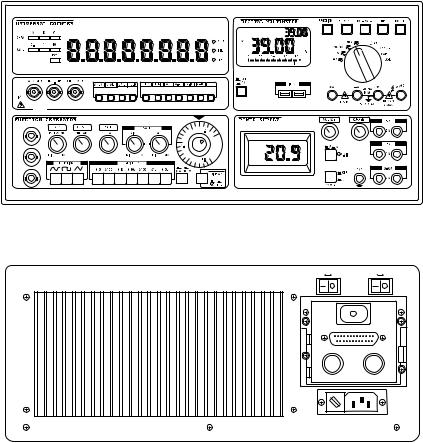
2. The MS-9160 Universal System
The MS-9160 Universal System is a compact, powerful measuring instrument for various application areas such as laboratories, service centres, schools, hobbies etc. This "All in One" instrument contains a function generator, a frequency counter, a DC voltage power supply with two fixed and one variable output voltages and a high quality (physically separate) multimeter.
The instrument in detail:
1.The function generator delivers seven different waveforms: sinusoidal, sawtooth, square, adapted sinusoidal (clockwise, counterclockwise), pulse, ramp and TTL level (square). The FG produces these waveforms in seven steps from 0.2 Hz to 10 MHz.
2.The frequency counter can measure frequencies from 5 Hz to 1300 MHz and display these on the 8-position LED display.
3.The DC voltage power supply delivers two stabilised fixed voltages, these being 5 V / 2 A and 15 V / 1 A. Additionally a stabilised, adjustable DC voltage is available of from 0 to 30 V with a current capacity of from 0 to 3 A. By means of a link the adjustable power supply output can be "grounded".
4.The digital multimeter measures voltage to 1000 VDC and 750 VAC, current to 20 A DC/AC, resistance to 40 MOhm, capacity to 400 uF and inductance to 400 mH max. It has a built-in logic tester and offers spe-
2 |
3 |
cial functions such as an RS 232 interface for connection to a PC, data hold and min/max value display, reference value measurement (=REL= relative), 5-location measurement value memory (=MEM), manual range selection (=R-H), dual display (=EXT) and comparison measurement (=CMP).
3. Safety requirements
3.1CE identification: The multi-measurement station MS-9160 is EMVapproved and complies with 89/336/EWG directives; in addition it is tested for safety and complies with 73/23/EWG low-voltage directives.
3.2The universal measuring instrument is constructed and tested to Safety Class 1 per VDE 0411 and VDE 0550 and left the factory in a perfect, technically-safe condition. To maintain this condition, the safety instructions and warning notices appearing in these instructions must be observed at all times. It is equipped with a VDEapproved power supply with safety cable and may only be used with and connected to 230 VAC supplies with safety grounding.
3.3Current measurements with the built-in multimeter may only be performed in current circuits, which are themselves fused at 16 A and in which no voltages greater than 250 VDC/VAC rms and powers greater than 4000 VA can occur. The measuring instrument may not be used in IEC 664 Overvoltage category III installations. The measuring instrument and instrument leads are not protected against arcing (IEC 1010-2-031, Section 13.101).
3.4Care must be taken to ensure that the (yellow/green) ground lead remains sound in the instrument, in its power lead and in the AC supply, because a damaged ground lead can result in danger to life. Care must also be taken to ensure that insulation becomes neither damaged nor destroyed.
3.5Measuring instruments and accessories do not belong in children's hands!
3.6In industrial facilities the accident prevention regulations of the Industrial Employers' Liability Association for electrical systems and equipment must be observed.
3.7In schools, training facilities, hobby and self-help workshops the handling of measuring instruments must be responsibly supervised by trained personnel.
3.8When opening covers or removing parts, except where this can be done without tools, live parts can be uncovered. Connection points may also be live. Prior to adjustment, service, repair or replacement of components or subassemblies when the instrument is required to be opened, it must be disconnected from all voltage sources and circuits being measured. If adjustment, maintenance or repair is subsequently required on the opened instrument while it is live, these must only be carried out by a specialist familiar with the associated hazards and relevant regulations (VDE-0100, VDE-0701, VDE-0683).
3.9Capacitors in the instrument may remain charged even when the instrument has been disconnected from all voltage sources and circuits.
3.10When effecting replacements, it must be ensured that only fuses of the specified type and specified current rating are used. The use of patched fuses or bridging of the fuse socket is not recommended. Before changing fuses, disconnect the measuring instrument from the circuit being measured, switch it off and disconnect the entire measuring instrument from the AC supply (pull out the AC plug). Remove all connected leads and test probes.
To change the DMM protection fuses carefully remove the second cover from the top (with a medium-bladed screwdriver). Remove the defective fuse(s) by unscrewing the fuseholder(s) counterclockwise and replace with identical type and specification 0.8 A quick-acting, 250 V; standard designation: F0.8A/250V and 20 A quick-acting, 250 V, F20A/250V (Bussmann types). Having successfully replaced the fuse(s) carefully screw the fuseholder(s) with the fresh, sound fuse(s) clockwise into their respective fuseholder(s). Then carefully close the fuse compartment again.
To change the power supply fuse, with a suitably-bladed screwdriver carefully lever up the cover (noting the notch) of the power supply voltage switch with the embedded power supply fuse. Remove the defective fuse and replace with an identical type and specification. For the 220 to 240 VAC supply the fuse is: 1A slow-
4 |
5 |
acting/250 V, standard identification: T1A/250V.
After successfully changing the fuse, snap the cover into the fuseholder. The arrow indication must correspond with the present AC voltage.
Attention!
Only use the measuring instrument when the housing has been safely closed and screwed together.
3.11Do not work with the measuring instrument in environments or under adverse environmental conditions where inflammable gases, steam or dust are present or can occur.
For safety reasons, it is essential to avoid the measuring instrument or test leads becoming damp or wet.
3.12Take particular care when dealing with voltages greater than 25 V AC or greater than 35 V DC. Even at these voltages a lethal electric shock can be received when touching electrical conductors. Therefore, first of all switch off the voltage source current, connect the measuring instrument to the voltage source points to be measured, set the required measuring range on the measuring instrument and only then switch on the voltage source again.
After the measurement has been completed, switch off the voltage source and remove the test leads from the voltage source.
3.13Before each voltage measurement ensure that the measuring instrument (multimeter) is not set to a current measuring range.
3.14Before each change in measuring range, the test probes must be removed from the test points.
3.15Before each measurement check the measuring instrument and test leads for damage.
3.16For measurements, use only the test leads which are enclosed with the measuring instrument. Others should not be used.
3.17To avoid electric shock, while measuring take care not to touch the test probes and the points to be measured (test points), even indirectly.
3.18The voltage between any digital multimeter socket and ground must not exceed 500 VDC or VAC rms. The voltage between any frequency counter socket and ground must not exceed 35 VDC or VAC rms.
3.19Never switch the measuring instrument on immediately after it has been brought from a cold into a warm area. The resulting condensation water could damage the instrument. Allow the instrument to come to room temperature before switching on.
3.20While working with power supplies, the wearing of metal or other conducting jewellery such as chains, bracelets, rings, etc. is not recommended.
3.21Power supplies are not intended for use with/on people or animals.
3.22When connecting the outputs of more than one power supply in series voltages dangerous to life (> 35 VDC) can result. Take particular care when dealing with voltages greater than 35 V AC or greater than 35 V DC. Even at these voltages a lethal electric shock can be received if electrical conductors are touched.
3.23Power supply ventilation holes should not be covered! The instrument is to be placed onto a hard, non-inflammable base, so that cooling air can enter unhindered. The instrument is cooled by means of a fan on its right side and by means of convection.
3.24Power supplies and their connected loads should not be left operating unsupervised. There are measures for the protection and safety of the connected loads in the face of power supply incidents (e.g. overvoltages, complete failure) and effects and dangers stemming from the loads themselves (e.g. unduly high current consumption).
3.25Faulty power supplies can produce voltages over 50 V DC, which can be dangerous, even when the indicated output voltages of the instrument are lower than this.
3.26For power-on work, only tools expressly approved for this should be used.
6 |
7 |
3.27The power supply outputs and their connecting leads, sockets and terminals must be protected from direct touch. In addition, the leads used must be sufficiently insulated and voltage-proof and the contact points safe from being touched (safety sockets).
3.28Use of bare metal leads and contacts should be avoided. All these items are to be covered by suitable, non-inflammable insulation or other arrangement and thereby protected from being touched. The electrically-conducting parts of the connected load must also be appropriately protected from direct touch.
3.29When safe operation is considered no longer possible, the instrument must be placed out of service and secured against unintended use. It is to be assumed that safe operation is no longer possible, if
-the instrument shows visible signs of damage,
-the instrument no longer functions and
-after prolonged storage under unfavourable conditions or
-after severe transportation stress.
3.30To reduce the danger of possible electric shock and to guarantee optimum operation of the measuring instrument, the case and chassis must be electrically grounded (via a grounded AC socket). The central ground (safety conductor) connector is in the socket on the rear of the case. The power cable supplied, equipped with a grounded plug, must be connected to an approved grounded socket.
3.31The frequency counter and function generator BNC sockets are floating, i.e. they are not connected to ground.
Attention!
Only for use indoors.
While opening or closing the case, the instrument must be disconnected from all voltage sources. To preclude any risk of additional sources of danger, never exchange components or subassemblies unaided and make no supposed improvements to this universal measuring instrument. Otherwise, the instrument can be damaged and thereby all guarantee claims become void.
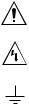
Warning instructions and their symbols!
Within these instructions the following various safety symbols can be found:
These symbols encourage the user to read the instructions carefully, to obviate damage to the instrument.
The "lightning strike" represents a dangerous voltage!
The earth/ground symbol indicates a grounding point.
CAT II = Overvoltage category II
Remarks and passages containing these symbols, which are indicated with "Attention!" or "Note!", must be followed without fail.
4. PUTTING INTO OPERATION
4.1Unpacking and checking the instrument!
Once the instrument is unpacked, check for the presence of all accessories and check the integrity of the instrument.
4.2AC power input
The Euro-socket, the AC fuse and the AC voltage-change switch are on the rear of the case. Plug the supplied AC power cable into the measuring instrument and its plug into a grounded AC socket. Ensure firm, safe connection of the AC power cable, both to the measuring instrument and to the AC socket.
4.3AC power voltage magnitude and type
The instrument operates with voltages from 220 to 240V AC with a permissible tolerance of ± 10 %, with a frequency of 50 Hz or 60 Hz.
4.4Changing the AC power voltage setting!
Attention!
Without fail, disconnect the instrument from all circuits being measured and above all from AC power before changing the setting. Remove the AC power plug from the socket, disconnect the AC power cable from the instrument and ensure that the instrument is absolutely free of voltages and not connected to any circuit.
8 |
9 |
Now remove the fuseholder (levering out with a suitable screwdriver). Note the arrow indication and replace the fuseholder in its fixture, turned by 90°, the arrow pointing to the desired AC voltage indication. Then reconnect the measuring instrument to the AC power (also check the AC voltage source).
4.5AC power fuse specifications
For an AC voltage of from 220 to 240 VAC, the current rating of the AC power fuse is 1 A with a voltage rating of 250 V. The melting characteristic of the AC power fuse is "slow-acting" (usual designation: T 1/250 V or 1 AT / 250 V).
4.6Digital multimeter fuses
For the 400 mA range (and below), the specified fuse has the following designation: F 0.8A / 250V or 800 mAF / 250V. The 20 A range requires: F 20A / 250V or 20 AF / 250V. The fuses can be found on the rear of the case, above the AC power plugs beneath the lockable cover.
4.7Setting up the instrument
To be able to view the DMM display and the controls on the front panel optimally and to avoid reading errors, it is recommended that both mounting feet under the front panel be hinged out and the instrument placed at least{216} 30 cm away from the wall (the 30 cm free space applies also for other set-up locations).
5. Working with the MS 9160
General view of the MS 9160 front panel with controls
FREQUENCY COUNTER |
FUNCTION GENERATOR |
||
OFF |
ON |
OFF |
ON |
|
RS232C |
|
FUSE |
|
FUSE |
220V/2A |
250V /20A |
|
240 |
|
|
220 |
100 |
|
120 |
|
|
POWER FUSE : 250 V / 1A
Rear view of the MS 9160
Foreword
Before beginning with measurements, read through the operating instructions carefully. Ensure that the instrument was set up, adjusted and connected in accordance with para. 4.
The following instructions are divided into four main groups:
5.1 |
Frequency counter |
5.2 |
Frequency generator |
5.3 |
DC voltage power supply |
5.4 |
Digital multimeter |
10 |
11 |
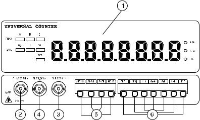
5.1 Working with the frequency counter
Frequency counter controls*
1.LED display
2.Input socket A for 5 Hz to 100 MHz, 1 MOhm
3.Input socket B for 0.2 Hz to 100 MHz, 50 Ohm
4.Input socket C for 100 MHz to 1300 MHz, 50 Ohm
5.Function buttons block I: ATTEN = Incoming signal attenuator
CHAN |
= |
A, B and C channel selection |
GATE |
= |
0.1sec, 1sec and 10sec gate time |
|
|
selection |
HOLD |
= Frequency value hold |
|
6. Function buttons block II: FREQ |
= |
Display of measured values in |
|
|
Hz, kHz or MHz |
PERI |
= |
Display of period in µs |
A/B |
= |
A/B relationship |
A => B = |
Time interval measurement |
|
A - B |
= |
Channel A minus channel B |
A + B |
= |
Channel A plus channel B |
TOT |
= |
Total = pulse counter |
* The AC power switch ("FREQUENCY COUNTER") for the frequency counter is at the rear of the MS 9160 case.
Attention !
Check for correct positioning of the AC power voltage switch in the AC power input module on the rear of the case. Check that the AC power fuse in the fuse holder is as prescribed, both while observing safety rules. (pull out the AC power plug!)
Make sure that the correct AC power switch is operated. The instrument should be warmed up for approx. 20 minutes for completely accurate operation.
Preparations
a)Initial switch settings
-Check the BNC socket for damage or short-circuit (visible check).
-Set the display selection switch to the FC position (not pressed in). This switch is in the the function generator controls area at the bottom right (under the round scale).
-Switch on the frequency counter. The switch is located on the rear of the instrument. Immediately after switch-on, the following self test occurs relatively quickly:
First, all LEDs, segments and decimal points light up, then "PASS_ALL" and afterwards "UC 1300" should be seen in the LED display.
-Set the gate time to 1 s (second) and then press the GATE button until the LED behind "1" lights.
-Press the CHAN (channel) button, until the LED behind A lights.
-Now read "0.0000000" on the display and immediately to its right read the measurement unit MHz.
b)Measurements
-According to in which frequency range measurements are to be carried out, select either channel A, B or C by pressing the CHAN button.
In CHAN A position, frequencies from 10 Hz to 100 MHz will be measured. This applies also to channel B. Channel C is for frequencies from 100 MHz to 1300 MHz.
-Setting the gate time. To achieve the highest possible resolution, select a suitable gate time.
-HOLD Function
If the button "HOLD" is pressed, the most-recently read frequency
12 |
13 |
will be "frozen", i.e. held. This remains so, even when the BNC lead is disconnected from the item being measured.
-Attenuator (1/20 gain) = ATTEN
If the incoming signal level is higher than 300 mV, this button should be pressed. For levels lower than 300 mV this button should not be pressed.
-Resolution
Resolution = decimal places, depends on the gate time (GATE) and the frequency: Gate time 0.1 sec., up to 5 decimal places; Gate time 1 sec., up to 6 decimal places; Gate time 10 sec., up to 7 decimal places.
-PERI = Period measurement
After pressing the PERI button, frequency is not displayed in kHz, rather its period (= time for one cycle) in µs (= microsecond = exp. -6)
-A/B = Relationship measurement
After pressing the A/B button, the relationship of channel A to channel B is displayed,
e.g.: 100 kHz (from the function generator) is present on channel A. If the same frequency is present also on channel B, Then "1.000000" is displayed, provided that both frequencies are absolutely identical.
-A-B = Difference measurement
After pressing the A-B button, the difference A minus B is counted.
-A+B = Addition of A and B
After pressing the A+B button the sum A + B is counted.
-Time interval measurement A ==> B
After pressing the A=>B button the time interval between A and B in µs (=microsecond) is displayed.
-TOT = "Total measurement" = pulse counter operation
Select this operating mode by means of the TOT button when pulses from electronic switches are to be counted. TOTAL means that the pulses are summed.
c)Display of signal generator output frequencies on the LED display
-To be able to read the signal generator frequencies on the LED display, the bottom right switch on the signal generator must be pressed.
-Because the signal generator can generate 10 MHz max., channel A should be selected, which can count up to 100 MHz.
-While the frequency of the built-in signal generator is being measured, the BNC socket of channel A is inoperative. That is to say even when an external frequency is introduced into channel A , only the frequency of the built-in signal generator is measured, provided that the F/C - F/G switch is pressed (set to F/G).
-Switch the frequency generator on, noting 5.2 without fail.
d)Measurement of external frequencies
1. Switch the measuring instrument and the counter on.
2. Select the channel by pressing the CHAN button.
3. Set a suitable gate time.
4. Connect a screened signal lead with intact BNC plug(s) to the input socket of the selected channels.
5. Select the correct attenuator (ATTEN) setting. For signals having an amplitude greater than 300 mV rms, the attenuator should be switched in. In this case the input signal voltage will be reduced by a factor of 20, to reduce measurement errors (measurement tolerance).
6. Read off the measured frequency and appropriate measurement units on the LED display.
e)Measurement of period
1. Switch the measuring instrument and the counter on. 2. Select channel A, B or C by pressing the CHAN button. 3. Press the PERI button once.
4. Connect a screened signal lead with intact BNC plug(s) to the BNC socket of the selected channels.
5. Read the period t of the signal in µs (=microseconds) on the display. Remember: f = 1/t and t = 1/f
f)Presentation of the relationship of channel A divided by channel B = A/B
1. Switch the measuring instrument and the frequency counter on. 2. Press the A/B button.
3. Connect two screened signal leads each with intact BNC plug(s) to the BNC channels A and B sockets.
4. Read the result in the display.
g)MMeasurement of time interval A=>B
A measurement is started by a signal fed into channel A and stopped by a signal fed into channel B. The time difference is shown in µs. If
14 |
15 |
100 kHz for example is fed into channel A from the built-in signal generator and 10 KHz into channel B, then a "time interval" of 100 µs results.
1.Switch the measuring instrument and the frequency counter on.
2.Press the A=>B button.
3.Connect two test leads with intact BNC plugs to the channel A and channel B BNC sockets.
4.Read the measured value in the LED display.
h)Measurement of channel A minus channel B
1.Switch the measuring instrument and the counter on.
2.Press the A-B button.
3.Connect two screened signal leads (or test leads) with intact BNC plugs to channel A and channel B BNC sockets.
4.Read the result of A minus B in the display.
i)Presentation of channel A plus channel B (A+B)
1.Switch the measuring instrument and the counter on.
2.Press the A+B button.
3.Connect two screened signal leads with intact (= undamaged) BNC plugs to channel A and channel B BNC sockets.
4.Read the result of channel A + channel B in the display.
k)Pulse counter operation = addition of single pulses (TTL) or square wave signals
1.Switch the measuring instrument MS-9160 and the frequency counter on.
2.Press the TOT button once, firstly to select the pulse counting operating mode and secondly to initialise = reset the counter.
3.Connect a screened signal lead with intact BNC plug to channel A or channel B BNC socket.
4.If the input level is greater than 300 m V rms, press the ATTEN button, firstly to attentuate the signal by a factor of 20 and secondly to reduce the possibility of measurement errors.
5.When the pulse-counting operation is completed, press the HOLD button to "freeze" the display before reading the displayed count.
l)Frequency counter signal input sensitivity
Channel A and B:
100 kHz |
to |
60 MHz |
< 20 mV rms |
60 MHz |
to |
70 MHz |
30 mV rms |
70 MHz |
to |
80 MHz |
50 mV rms |
80 MHz |
to |
100 MHz |
70 mV rms |
Channel C: |
|
|
|
100 MHz |
to |
1,3 GHz |
< 25 mV rms |
5.2 The function generator
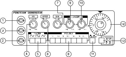
Function generator (FG) operation |
|
||
1. |
VCF input socket |
8. Switch for frequency range |
|
2. |
FG output socket |
9. SWEEP (band)width control |
|
3. |
TTL level output |
10. |
SWEEP speed control |
4. |
Amplitude control knob |
11. |
Connection impedance switch |
5. |
Waveform switch |
12. |
Frequency adjustment with scale |
6. |
OFFSET control knob |
13. |
Display counter/generator switch |
7. |
Symmetry control knob |
|
|
Attention!
Before switching the instrument on, check that both the position of the AC power voltage selection switch and the AC power fuse are correct. Ensure that the correct AC power switch on the rear of the case is used to switch on function generator. So that the generator functions completely accurately a warm up time of approx. 30 minutes is required.
16 |
17 |
Preparation
a)Initial settings
-Check the contacts of the BNC sockets for damage and short circuits
-Set the display switch to the position F/G. The switch is located at the bottom right of the function generator
-Set the function switch to sine function
-Set the frequency selection switch "FREQUENCY" to 1 kHz
-Set the frequency adjustment control knob (scale) to the position 1.0
-Press all buttons such as AMP, OFFSET, SYM, SWEEP (WIDTH and RATE), until they are latched in
-Set the output impedance to the required value (50 or 600 Ohm)
-If frequency is to be measured, note subclause c) of the function generator instructions.
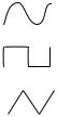
b)Output waveforms
The generator can deliver three standard basic waveforms: SINE, SQUARE and SAWTOOTH. For these, press one of the switches under FUNCTION.
:Sine waveform
:Square waveform
:Sawtooth waveform
c)Frequency range
Press one of the seven buttons under FREQUENCY, to set the desired frequency range. The selectable ranges are given in the following table:
Switch position |
Frequency range |
|
x 10 |
approx. 1 Hz to 10 Hz |
|
x 100 |
approx. 10 Hz (2 Hz) to 100 Hz |
|
x 1k |
approx. 100 Hz (10 |
Hz) to 1 kHz |
x 10k |
approx. 1 kHz (100 |
Hz) to 10 kHz |
x 100k |
approx. 10 kHz (1 kHz) to 100 kHz |
x 1M |
approx. 100 kHz (10 kHz) to 1 MHz |
x 10M |
approx. 1 MHz (110 kHz) to 10 MHz |
Note!
The values in brackets are achieved when the frequency adjustment control knob is almost at its left stop. They are dependent on the output amplitude and the load connected to the generator output.
22
-Set the Hi/Lo switch on the frequency counter to Lo and the gate time to 1 sec. (lower LED row, centre LED).
-Set the display switch (bottom right on the FG) to F/G, in case not yet done.
-The generator frequency can now be read in the LED display.
d)Voltage controlled Frequency VCF
-The output frequency of the generator can be adjusted by connecting an external voltage to the VCF input (BNC).
-The output frequency can be adjusted by a factor of 1:20 by an input voltage between 0 and 10 VDC, dependent on the setting of the frequency range button.
-To be able to work with the VCF function, it is necessary to place the frequency adjustment control knob (scale) to its left stop (two graduations next to "0.1" on the right) and to connect the external DC voltage to the VCF socket (BNC) (observing the inner "+" polarity).
e)Setting the output amplitude
-The amplitude of the output voltage with open output is 20 V p-p. With 50 Ohm or 600 Ohm load the output voltage approximately halves, i.e. to 10 V p-p.
-The amplitude of the output voltage is set with the AMP control knob.
-By pulling this control knob the amplitude is set to -20 dB.
-To guarantee a precise waveform in the range from 1 MHz to 2 MHz, set the "AMP" control knob to 5 V p-p.
18 |
19 |