

Моделирование бизнес-процессов / Моделирование бизнес-процессов / ERwin_Insider
.pdfwith a meter class or a non-meter class but not both. The problem with this structure is that I did not find it in any reference to this structure by either Grady or Booch..
Figure 37A
Categories VS Subtypes
A category in IDEF1X is essentially the same concept as subtype in UML. These terms are the semantics used to describe the phylum, or genera of an entity or a class. An entity called aircraft could have categories the like of helicopter, single engine aircraft, jet aircraft etc. The class called shape could have subtypes named rectangle, circle and polygon. The structures created to represent categories are referred to as generalization hierarchies. In both UML and IDEF1X, the parent to which the genera are related is called a generalization. The child or subtype in the generalization hierarchy inherits all the characteristics of the parent. In an IDEF1X/relational diagram the categories will inherit all the attributes of the parent. In a UML diagram, the subclass will inherit all the attributes and methods from the parent class. As similar as they are in concept, so to are the similarities in structure.
Figure 38
In this example both structures show that an organization can have three types of persons working for it, an employee, a contractor, or an intern and that these three categories are mutually exclusive.
There are additional adornments to these structures. The category discriminator (IDEF1X) and the discriminator (UML) are constructs which display the attribute in the generalization that determines the differentiation between the categories.
In this regard, IDEF1X is a bit more expressive than UML. In a normalized data model, the discriminator attribute will more than likely be the key of a code table. IDEF1X has the ability to display this because keys are an integral part of the diagram. UML, as has been pointed out a number of times, because of the
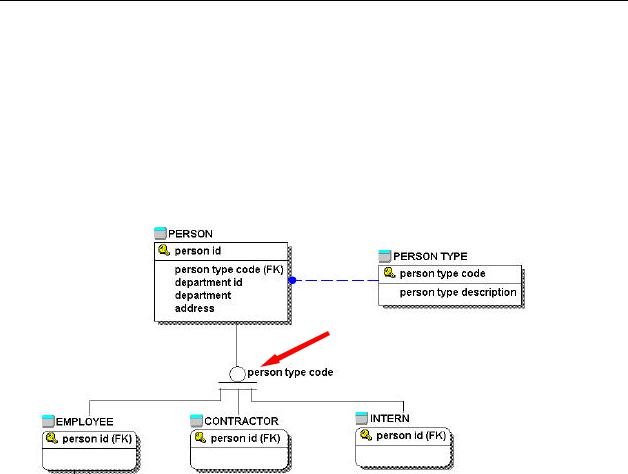
nature of the object paradigm with regard to keys, does not provide for the discriminator attribute. Figure 39 shows the PERSON generalization with categories, attributes, the PERSON TYPE code table whose
Figure 39
key, the person type code is contributed to the person table as a foreign key and acts as the discriminator attribute for the category discriminator (show below and adjacent to arrow). Figure 41 show the discriminator in UML notation.
The generalization show in figures 38 and 39 represent the “or” category structure. This means that in both the UML example and the IDEF1X example, only one of the categories can exist for an instance of the category. In other words, the business rule displayed is that a person can either be an employee, a contractor or an intern but not a combination thereof.
Figure 41 shows “and” category generalization structures in both IDEF1X and UML, where for, one instance of the generalization, there can be a combination of categories. This example expresses the rule that one account can have checking, savings and a loan. Here again IDEF1X and UML similarly display these rules. Note that the notation
symbols for the “or” category structures are joined prior to attachment to the generalization, whereas the notation for the “and” category structures are separately attached to the generalization.

Figure 40
Figure 41
Inheritance
Inheritance is a concept many think belongs solely to the object world. Inheritance refers to “The mechanism by which more-specific elements incorporate the structure and behavior or more-general elements.”20 21But inheritance does really exist in the relational world. The notion of all the attributes of a generalization applying to its categories, is inheritance.
In UML, however, inheritance displayed in a generalization has some expanded dimensions. Figures 38, 39, 40 and 41 all display structures of single inheritance. In these model structures all the children inherit characteristics and
20 p. 462 The Unified Modeling Language User Guide by G. Booch et al 1999 Addison Wesely

behavior from a single parent. UML provides notation that displays multiple inheritance. This means children inherit characteristics and behavior from more than one parent. Figure 41 shows and example of UML notation for multiple inheritance.
Although there IDEF1X does not allow for multiple inheritance in a category hierarchy, the concept can be shown using two entities connected via identifying relationships to a third entity (associative table). The result is the same. The associative table, in effect inherits the characteristics of the two identifying tables. See figure 27.

Figure 42
Multiple and Complex Generalizations
Multiple and complex generalizations can be represented in IDEF1X using combinations of the and category structure and the or category structure. In a similar fashion, multiple and complex generalizations can be represented in UML. Figure 43 shows an example of multiple generalization in IDEF1X and figure 44 shows a class with multiple generalizations in UML.
Figure 43

Figure 44
Both UML and IDEF1X permit relationships/associations between entities/classes in category structures and entities/classes external to the category structure. These relationships/associations can be between the “external” entity/class and both the super-type or a subtype. Figure 39 shows an example in IDEF1X, and Figure 42 shows an example in UML.
UML can take complex generalizations to an even higher level of complexity. UML allows business rules between categories (sub types) of a generalization to be applied. Figure 45 shows an explosion of figure 45 with a relationship between the savings account category and the loan account category of the account class22. The relationship defines the rule that; for every loan there must be at least one or more savings accounts as collateral for a loan. These associations are, in effect, similar to a recursive relationship.
Figure 45
22 The are refer to as “specialization object classes by Dorsey & Hudicka p. 350

These complex relationships can exist within both and category structures & or category structures.
If you though this was complicated it can be worse. Just like UML provides for associations within generalizations, it also provides for the creation of generalizations between associations. Rumbaugh calls this a generalization of composition association.
For a further discussion on the specifics of this generalization, refer to The UML Reference Manual23.
Aggregation
An aggregation is “a form of association that specifies a whole -part relationship between an aggregate (a whole) and a constituent part.”24 In a more succinct definition...“Class A is said to be an aggregation of class B if an object in class A is defined as a collection of objects from class B. Objects from class B need not be attached to any object from class A….The master is made up of the details. However it is relevant to talk about the details out side of the context of the master”25
Rumbaugh gives the following example which we all can appreciate; A path on ones PC is a combination of segments. Each of t hose segments could actually exist in and of itself. The path is therefore considered to be an aggregation.
In the example shown in figure 46, we find that a team is made up of players. It is relevant to talk about the players regardless of the team they play on. The aggregation symbol has been highlighted with a red circle.
23p 232 The Unified Modeling Language Reference Manual by J. Rumbaugh 1999 Addison Wesely
24P. 458 The Unified Modeling Language User Guide by G. Booch 1999 Addison Wesley
25p 233 Oracle 8 Design Using UML Object Modeling by Dorsey & Hudicka, 1999 Oracle Press

Figure 46
The concept of aggregation is one of a number of more rarified forms of relationship which, in keeping in line with its simplicity, were not developed in the relational model in terms of symbolic representation. An aggregation would be represented in IDEF1X as would any one to many relationship.
UML uses a filled diamond (see figure 46) on the “parts” side of an aggregate association to represent the aggregation.
Booch states that aggregations are an exercise in semantics. “Simple aggregation is entirely conceptual and does nothing more than distinguish a “whole from a “part”. Simple aggregation does not change the meaning of navigation across the association between the whole and its parts, nor does it link the lifetimes of the whole and its parts.”
Although there is no IDEF1X symbol per se to represent an aggregation, the concept is familiar to the relational modelers in the form of referential integrity rules. An aggregation is when there are no cascade delete rules placed either on the parent or the child in a relationship. In an ERwin physical model diagram (either IDEF1X or IE) this can be expressed in a diagram that has the option to display referential integrity rules switched on. The rules are represented using the first letter of each of the two rule elements and a colon.
D:R = Delete Restrict
U:R = Update Restrict
D:C = Delete Cascade
In the example at hand, (See Figure 49) The notation for cascade delete (D:C) would not appear.
Figure 47

Composition
A composition is a tight form of association. As Dorsey & Hudicka put it “The detail object must belong to the master.” In a composition, “it is not meaningful to discuss the detail out of context of the master. If the master is deleted all the details would logically have to be deleted.”26
In more formal terms Rumbaugh states a composition is “A form of aggregation association with string ownership and coincident life time of parts by the whole. A part may belong to only one composite. Parts with non-fixed multiplicity may be created after the composite itself. But once created, they live and die with it (that is, they share lifetimes). Such parts can also be explicitly removed before the death of the composite.”27
A purchase order is the most obvious example of composition. A a purchase order can be created prior to the line items, while the line items can’t be created with out the PO. Line items can be inserted or deleted during the life of the purchase order, but if the purchase order is eliminated the line items must be eliminated with it. The UML notation for a composition is a hollow diamond. Figure 48 shows how a purchase order and its line items can be represented in UML.
As in the case of aggregation, although there is no IDEF1X symbol per se, to represent an aggregation the concept is familiar to the relational modelers in the form of referential integrity rules. A composition exists when cascade
delete or update cascade rules apply in a parent child relationship. As Codd puts it, “these rules together capture and reflect the necessary existence dependency.”28 Codd calls these “weak entities” in a many-to-one relationship. In an ERwin physical model diagram (either IDEF1X or IE) this can be expressed in a diagram that has the option to
display referential integrity rules switched on. The notation for cascade delete (D:C) would appear. (see Figure 49 ). The composition notation has been highlighted with a red circle.
Figure 48
Figure 49
In an object relational diagram compositions can be represented as nested tables or varrays, both of which are beyond the scope of this discussion.
26ibid 236
27- p. 226 The Unified Modeling Language Reference Manual – Rumbaugh, 1999 Addison Wesley
28p. 360 An Introduction to Database Systems 6th Edition by C.J. Codd 1995 Addison Wesley

Dependency
A dependency is another type of UML relationship that is significant to this discussion. (The other two, generalizations and associations have already been discussed.)
“A dependency is a using relationship that states that a change in specification of one thing may effect another thing that uses it, but not necessarily the reverse.” Or ‘ A relationship between two elements in which a change to one element (the supplier) may affect or supply information needed by the other element (the client)”29
The notation for a dependency can be a little confusing. It is a dashed line with an arrow pointing to the dependent class or interface30 end. That is the arrow points in the direction class where the change will radiate from. Figure 50 shows an example of a dependency. Modification is a collection of operations which could act upon Component.
Figure 50
Obviously, operations are not documented in a IDEF1X diagram. Here to, the construct but not the concept is remote to IDEF1X. This collection of operations is somewhat similar the triggers and stored procedures associated with a relational table.31 Modeling tools such as CA-Erwin provide the functionality to create and document triggers and stored procedures.
Figure 51
29p. 250 The Unified Modeling Langugage Reference Manual by J. Rumbaugh 1999 Addison Wesely
30An interface is a UML construct which represents a collections of operations which can be performed by a class.
In
31This can be compared to a package in Oracle which is a group of related PL/SQL procedures and functions