

Моделирование бизнес-процессов / Моделирование бизнес-процессов / ERwin_Insider
.pdfmulti-dimensional (relationships exist between multiple occurrences on each side of a relationship) and therefore, in order to build it in a relational database it must be resolved with another table. This table is known as an association table. A many to many relationship in an IDEF1X logical model is permissible but can only exist as a logical structure. In order to physically implement it in a database the many to many relationship must be resolved. Hence the many to many relationship in a physical model is not allowed by modeling tools.
UML, on the other hand, permits a many to many relationship in a physical model. This can be problematic when using UML to create a model for an object-relational database. In this situation the modeler can resolve the many to many relationship by creating an associative class.
Figure 20 compares an IDEF1X many to many relationship resolved by an associative entity (referred to by some as an intersection entity), with a UML many to many relationship resolved with an associative class. Although the associative class is a valid UML notation, some UML modeling tools do not provide for the associative class in their tool box.
Figure 20
Complex Relationships
The power of UML’s multiplicity notation shines when taking into account complex relationships. Consider a relationship between a person class and a committee class where the following rules apply:

A person does not have to be on any committee, however if he is a member, he cannot be a member of more than two. Each committee must have at least three people, but can’t have more than 20. Figure 21 shows how these rules can be easily represented in UML.
Figure 21
Applying the mnemonic referred to in an earlier section, 0..2 in effect says that a PERSON requires from zero to 2 COMMITTEE in order to exist. The zero in “0..2 “ indicates that a PERSON does not have to be on any COMMITTEE and the 2 indicates that he can’t be on more than two. 3..20 relates the rule that a COMMITTEE must have at least 3 PERSON but can’t have more than twenty in order to exist.
IDEF1X notation does not provide the ability to graphically represent these rules. This does not mean that these rules cannot be enforced in a relational database. Stored procedures can be created to assure these constraints are controlled by the database. Some IDEF1X modeling tools such as CA-ERwin facilitate coding of stored procedures belonging to particular tables. The stored procedures can be viewed from pop up window menus when clicking on tables within a diagram. However they cannot appear in any methodology notation in the diagram itself. The rules could be stated in text placed near the appropriate entity.
Diamonds vs Nulls
A primary key or any part thereof cannot contain a null value. Therefore, in an IDEF1X relationship where the parent contributes a primary key to the child (identifying relationship), the contributed key can never be null. This relationship is characterized as and identifying relationship which is mandatory. (See figure 22.)
Figure 22
In a relationship where the parent’s key is contributed as a foreign to the non key area of the child, (non identifying relationship) depending on the business rule, the option exists to forbid or allow the foreign key to contain a null value. A non identifying relationship in which the contributed foreign key(s) may not be nulls is known as a mandatory non identifying relationship. A non identifying relationship in which the contributed foreign key(s) can

be nulls is known as an optional non identifying relationship. IDEF1X provides the ability to note graphically, using the diamond symbol, whether or not the contributed non identifying foreign key(s) are allowed to contain a null value. Figure 23 shows an mandatory non identifying relationship. Figure 24 shows an optional non identifying relationship with the hollow diamond symbol.
Figure 23

Figure 24
As referred to earlier, the concept of identifying and non identifying relationships does not exist in UML because of the use of OIDs. In effect, all UML relationships are optional and non identifying. UML does provide notation for nulls as explained in the following section.
Data Types
UML as in a IDEF1X physical diagram, provides for display of attribute data types. Figure 25 shows data types in a IDEF1X and figure 26 shows data types in UML.
Figure 25
Figure 26

Both UML and IDEF1X include display initial values the diagrams. Figure 27 shows how initial values are displayed in IDEF1X and figure 28 shows the same in UML. (Therefore if the initial value of an attribute is null it could be displayed in UML as shown.)
Figure 27
Figure 28
IDEF1X does have a bit of a redundancy in that the contributed keys in a non identifying optional relationship shows the null option by both the diamond graphic and the null literal. (See Figure 29). They both indicate the same thing.

Figure 29
N ary Relationships
An N ary relationships exists when there are, relationships or associations among a multiple number of tables. In IDEF1X Nary relationships must always be through an association table because, as mentioned above, relationships are binary, and must connect exactly two entities.
The relationships are shown in IDEF1X with an association table acting as the intersection between all of the relationships. (see figure 30) Each of the other tables contributes its key to the association table. This creates a binary “network” between the student, professor and course tables.
Figure 30
In UML the Nary associations are shown with an N ary association, a large diamond with an association between the diamond and each class. (A diamond in IDEF1X means nulls, but in UML it refers to an association class). Figure
31 shows how an Nary association is displayed in UML.
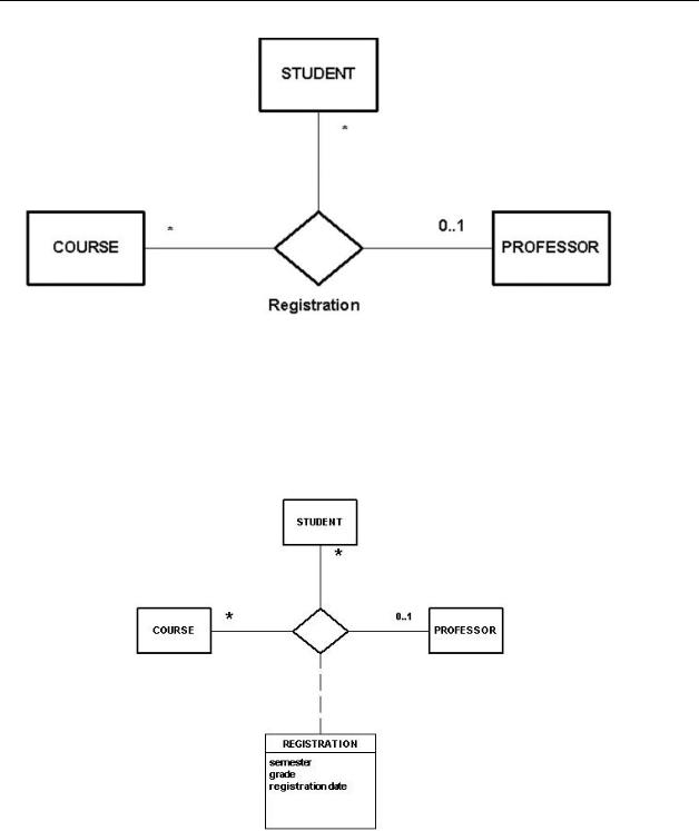
Figure 31
An association class symbol can be attached with a dotted line to the n ary association diamond. (See figure 32) As referred to above this association class in optional in UML, where as the associative relationship is required in an IDEF1X physical diagram.
Figure 32

Verb Phrases
Verb phrases help describe the rules defined by relationships. Erwin / IDEF1X, offers the option to describe a relationship in one or both directions. (See figure 33) The upper verb phrase describes the relationship from the parent to the child entity, while the lower phrase describes the relationship between the child and the parent. 15
Figure 33
Verb phrases play a similar role in UML which, as does ERwin/IDEF1X, offers the opportunity to include verb phrases for both directions of an association. In addition to the verb phrases, UML provides the ability to assign a name to the association which becomes the constraint name in the physical data base
(see Figure 34).
In IDEF1X the verb phrase assigned to the parent child relationship defaults to the relationship constraint name when forward engineering the model into the physical database.
Additionally, in UML, a filled arrow can be used to indicate direction, and hence the ordering of classes. This is called the “name arrow” and indicates which way to read the association name. This filled arrow is used purely as a notational device.
Figure 34
Attributes
1st Normal Form VS Attribute Multiplicity
Defining the first normal form, C .J. Date writes, “At every row-and-column position within the table, there is always exactly one value, never a collection of several values. Or equivalently again: Relations do not contain
repeating groups A relation satisfying this condition is said to be normalized, or equivalently to be in the first normal form.” 16. This rule is one of the keystones of relational theory and hence IDEF1X. Attribute multiplicity is just not an acceptable concept in the IDEF1X lexicon. Not so, in the object paradigm! UML allows for multiplicity to be shown for attributes. All of the multiplicity notations which apply to associations can be applied to attributes, as shown in figure 35. A number, a range of numbers, and the many notation can be placed adjacent to an attribute to show that there can be multiple occurrences of that attribute contained in a class. There is an important differentiation to make between attribute multiplicity and association multiplicity. When there is no multiplicity indicated in either an association, the multiplicity takes on the default of many. When there is no multiplicity indicated for an attribute it tales on the attribute multiplicity default of one.
15Originally Erwin/IDEF1X only offered the parent to child verb phrase. In answer to user demand, Erwin added the lower verb phrase to describe the child to parent relationship.
16P. 93 An Introduction to Database Systems 6th Edition by C.J. Date 1995 Addison Wesley

PERSON
name:Name
phone[*]:Number address[1..3]:Address
Figure 35
Constraints
Contingent Constraints
The best way to show the similarities and differences between IDEF1X and UML with regard to contingent constraints, is to present a set of business rules and show how they would be modeled in both languages.
In our example, we wish to model the relationship between PERSONs and the COMMITTEEs they can serve on. The following business rules apply;
•
•
•
•
•
Each PERSON may be a member of zero or more COMMITTEEs. Each COMMITTEE must have at least one PERSON as a member. Each COMMITTEE must have one PERSON as a chairman.
Each PERSON may be the chairman of zero or more COMMITTEEs. Chairman must be a member of the COMMITTEE.

Figure 3617
The “1..0” multiplicity on the COMMITTEE end of the MEMBER association indicates that there must be at least one to an unlimited number of members on each committee. The “*” on the PERSON end of the MEMBER association indicates that any one PERSON can be a member of an unlimited number of Committees. The CHAIRMAN association indicates that any PERSON can be a CHAIRMAN of any number of COMMITTEEs (shown by the * on the PERSON end of the association) and each COMMITTEE must have a CHAIRMAN and can have only ONE CHAIRMAN (indicated by the “1” on the COMMITTEE side of the CHAIRMAN association). There is no notation available in UML to show the rule that a chairman must be a member of the committee, there for it is shown here in UML’s note construct attached to the CHAIRMAN association. The note in UML serves the same function as does text in an IDEF1X diagram. “It has no semantic impact, meaning that its contents do no alter the meaning of the model.”18 As technology progresses some modeling tools will offer the ability to embed URL or other executable in these notes, making them very dynamic.
Figure 37 shows how the same contingent constraints would be modeled in IDEF1X. These two diagrams highlight one of the most significant differences between IDEF1X and UML. All the constraints are displayed in both diagrams. IDEF1X’s simplified format contains the constraints, yet UML with it’s more robust notation, displays all the constraints more expressively, but in a fashion that is a bit more difficult to read. Plainly put, IDEF1X VS UML
is Simple VS complicated, subdued VS exp ressive.
Figure 37
Or Constraint
Dorsey and Hudicka present19 a nifty notation which I missed not having in IDEF1X, the Or constraint symbol. The symbol is a dashed line laid across two or more classes which are associated with a class common to all of them. It indicates that for one instance of the common class I can only have only one instance of either of the classes strapped by the dashed line. In the example below shows that one instance of an account class can be associated
17The inspiration for this example was from p237 of the Unified Modeling Language Reference Guide by J. Rumbaugh 1999 Addison Wesely.
18P. 78 The Unified Modeling Language User Guide by G. Booch 1999 Addison Wesely
19P. 290 Oracle 8 Design Using UML Object Modeling by P. Dorsey & J. Hudicka 1999 Oracle Press