Моделирование бизнес-процессов / Моделирование бизнес-процессов / ERwin_Insider
.pdf
Overview
It is possible to use ERwin/ERX %Lookup Macro to automatically abbreviate the business attribute names of the Erwin Logical Domain to the short column names of the Erwin Physical Domain. Once the required parameters are setup correctly, simply switching from one domain window (logical), to the other (physical) can automatically abbreviate all business names contained in the logical model to the corresponding short column names in the physical model.
The process converts a business name to its abbreviation, as defined by the user in a separate comma delimited text file that the %lookup macro uses. What it does not is adjusting the resulting abbreviated column name to standard RDBMS length e.g. 18 characters for DB2; it remains the analyst responsibility to review the resulting translation for the RDBMS’ standard length correctness.
The requirements needed to convert business names are two steps:
1.Create a comma delimited text file of the needed business names and their abbreviations sorted in descending order, in the format of ‘name,abbreviation’ e.g.:
Relational Database Management System,RDBMS
name,nm
business,bus
Etc.
2.Using ERwin/ERX Domain Dictionary Editor in Physical Edit mode:
In the General tab “Name Inherited by Column” field, create an entry that uses the %Lookup macro and points to a comma delimited text file of business names and their corresponding abbreviations.
To prevent re-entering the needed setup with each new model, a pre -defined ERwin Template of extension .ERT containing all the needed macro setup can be used as a startup template for all new models. Alternatively a previously created model can be copied and pasted into a new model created from the Template.
The following pages show step by step instructions for setting up the macro in an Erwin model.

Sample %Lookup Macro Setup
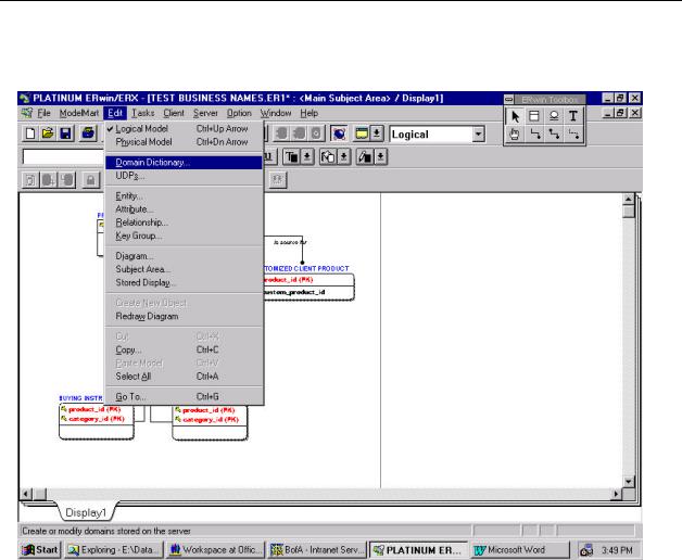
1)First open a new or old model in Erwin.
2)Then open the Domain Dictionary Editor as shown above.

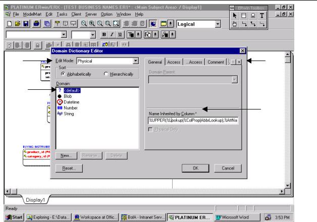
1)Insure that the Edit Mode selection is clicked on Physical (upper left).
2)Make sure you are in the General tab (upper right).
3)Insure that the higlighted Domain is ?Default.
4)Enter the following macro in the “Name Inherited by Column” field: %UPPER(%Lookup(filename,%AttName))
(filename is the fully qualified comma delimited abbreviations text file) e.g. %UPPER(%Lookup(c:\Erwin\abbreviations.txt,%AttName))
5)Click OK.
With this setup the instant you switch from the logical domain view of the diagram to the physical domain view of the diagram all the column names will be abbreviated according to the external file specification. The %UPPER macro converts lower case letters to upper case. All spaces will be replaced with underscores.

Special Considerations
1.Order of the comma delimited text file:
Care should be taken to sort the comma delimited text file in descending order. The lookup macro will use the abbreviation as soon as it finds an exact match, thus if your file is sorted in ascending order workstation will abbreviate to wrk for work because the word work comes before workstation. By the same token compound names and acronyms should be placed at the very beginning of the file. e.g.
Ascending order:
WORK,WRK
WORKSHEET,WSHT
WORKSTATION,WSTN
Descending order:
WORKSTATION,WSTN
WORKSHEET,WSHT
WORK,WRK
2.Cutting and pasting a model:
When using the “cut & paste” method to bring into a template a model that was previously created in Erwin without using the %lookup macro, the resulting column names will all default to %AttName . To fix this problem you will need to invoke the Column Editor in the Physical View and use the Reset Column Property feature; this feature will translate the %AttName to the proper abbreviated column name.
In the Physical View, click on any table; invoke the column editor, in the column editor click on the reset button. In the Reset Column Property window select “all columns in model” then select “select all” button, click enter. This will replace the %AttName with the real abbreviated column names.


ERwin Key Board Short Cuts
Ben Ettlinger
Data Administrator, New York Power Authority
New York Enterprise Modeling User Group
Key Stroke |
Function |
cntl A |
Select All |
cntl B (logical) |
Independent Attribute Browser |
cntl B (physical) |
Independent Column Browser |
cntl C |
Go To window |
cntl S |
Erwin Save As window |
cntl T |
Erwin Tool Box |
cntl X |
Delete window |
cntl V |
paste |
cntl + |
zoom in |
cntl - |
zoom out |
cntl * |
no magnification |
cntl é |
shift to logical |
cntl ê |
shift to physical |
cntl è |
shift diagram right |
cntl ç |
shift diagram left |
cntl insert |
copy window |
cntl shiftè |
shift diagram right |
cntl shift ç |
shift diagram left |
cntl shift é |
move diagram up |
cntl shift ê |
move diagram down |
cntl alt é |
move diagram up |
cntl alt ê |
move diagram down |
cntl alt è |
shift diagram right |
cntl alt ç |
shift diagram left |
cntl home |
top of diagram |
cntl end |
bottom of diagram |
cntl shift F6 |
no magnification |
cntl shift F4 |
close diagram window |
cntl shift enter |
opens editor for highlighted object |
cntl alt enter |
opens editor for highlighted object |
cntl enter |
opens editor for highlighted object |
cntl shift delete |
deletes highlighted object (warning message) |
cntl alt delete |
deletes highlighted object (warning message) |
cntl delete |
deletes highlighted object (warning message) |
windows icon |
start menu |
F1 |
On Line Help |

Model Mart Key Board Short Cuts
Ben Ettlinger
Data Administrator, New York Power Authority
New York Enterprise Modeling User Group
Key Stroke |
Function |
cntl shift B |
Report Browser |
cntl shift F |
Save Model Mart Diagram As window |
cntl shift L |
Model Mart Log |
cntl shift Q |
Send Query window |
cntl shift V |
Volumetrics Editor |
cntl shift Z |
Model Mart Timing |
cntl shiftè |
shift diagram right |
cntl shift ç |
shift diagram left |
cntl shift é |
move diagram up |
cntl shift ê |
move diagram down |

IDEF1X VS UML
A Comparative Analysis
By: Ben Ettlinger
Data Administrator
Information Technology Division
New York Power Authority
© 1999 New York Power Authority

IDEF1X VS UML – A Comparative Analysis
Why Compare?
Why in the world would anyone want to do something like this? Why compare IDEF1X, one of the most popular relational data base modeling languages, with UML, the hybrid language which has taken first place as the language for modeling in the object world? Relational and object, two different paradigms, two different architectures, two different notations…apples and oranges ..right? Well, not really.
True, objects, and the modeling languages that go with it, encapsulate concepts far beyond the simplicity of the relational paradigm. An object database can express business rules and functionality, never imagined (or cared to imagine) in a relational data base environment. Why bother looking back at the “old” technology if objects offers the ability to capture “static structures and dynamic behavior of a system” 1 with greater visual detail. The answer is simply, simplicity.
The object paradigm is complex. Inheritance, encapsulation, polymorphism, stereotypes, realization etc. are concepts whose understanding can be daunting, difficult to model and even more difficult to try to explain to others. The is another important element to consider here. The fact is, most business applications can be satisfactorily built using the relational database. After a presentation at the recent CA -World covering the topic at hand, the data administrator of one of the largest mail order firms seriously questioned why would anyone want to build an object data base. Her firm was doing all the latest and greatest, including
e-commerce gee whiz with a web page that allows the customer to enter measurements a see how the clothes fit. The relational database they are using is supporting it all just fine
My original interest in comparing the two paradigms was generated by complexity of objects. I needed a point of reference to which I could refer, compare, analyze and then hopefully understand. This article just represents the process I used to get a handle on UML.
I don’t believe that it’s just my struggle. At every user group meeting or conference I have attended, inevitably two questions are asked. The first; Did you ever hear of UML? Almost every hand goes up. The second question; Do you know what it is all about , or do you understand it? Almost no hands go up!
But the comparison is really more than just a point of reference. A real need to map data from the object to the relational world has sprouted. As discussed in great detail in a recent article by David Linthicum in the April 1999 issue of Component Strategies, aside from the purely object databases, we have seen in recent years a growth of hybrid, or universal databases which mix the two paradigms, and tools which offer sophisticated middleware which traverse both relational and object database. Future direction according to Linthicum, will increase the need to traverse between relational and object. “As the demand for OO databases rises and the popularity of relational database remains, developers will continue to seek a quick fix via object-to-relational translation layers..” Clearly”, conclude Linthicum, this [the universal database ] is the future of object-to-relational integration.
Why ERwin and Paradigm Plus?
In this analysis of the relational and object paradigms we will be using a relational and an object modeling tools. On the relational side we will display screen shots of IDEF1X modeling language as presented in Computer Associates’ ERwin data modeling tool. On the object side we will be using Paradigm +, CA’s object modeling tool which employs UML, the Unified Modeling language, which has become the standard for object modeling. The reason for using these tools is simple. ERwin is by far the most widely used IDEF1X modeling tool and the with which I am most comfortable, and Platinum (now CA) sent me a complementary copy of Paradigm Plus that would not expire in 30 days, Rational Rose, vendor of a popular UML tool, did not.
1 The Unified Modeling Language Reference Manual p.3 James Rumbaugh et al 1999 Addison Wesley

ER Diagram VS Class Diagram
IDEF1X contains only one diagram, the entity relationship diagram, in its palette. UML, which is larger in scope and takes on application development from high-level business process analysis to application deployment, has a more robust palette which includes eight diagrams. Figure 1 below illustrates how each UML builds on one another to refined and develop the requirements for a business application from the high level use case diagram to the relationship between hardware components and software components in the package diagram. The class diagram is the heart and sole of the UML. As does its relational counterpart the entity relationship diagram, the class diagram maps out the objects of a database in a fashion that spells outs the business rules and requirements.
Figure 1
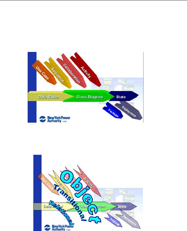
This discussion concentrates on comparing many of the constructs and business rule representations of the two diagrams which bring the two methodologies closest, the entity relationship diagram (data model) and the class diagram. This is the point (see figure 2), where the transitional layer between the relational and object paradigms would come into play.
Figure 2
