

laser_measurement_instruments_catalog
.pdfWavelength Range and Repetition Rate for Energy Sensors
Wavelength Range
MODEL |
|
|
|
|
|
|
|
|
|
|
|
|
|
|
|
|
|
|
|
|
|
|
|
|
|
|
|
|
|
|
|
|
|
|
|
|
|
|
|
|
|
|
|
|
|
|
|
|
|
|
|
|
|
|
|
|
|
|
|
|
|
|
|
||
|
|
|
|
|
|
|
|
|
|
|
|
|
|
|
|
|
|
|
|
|
|
|
|
|
|
|
|
|
|
|
|
|
|
|
|
|
|
|
|
|
|
|
|
|
|
|
|
|
|
|
|
|
|
|
|
|
|
|
|
|
|
||||
|
|
|
|
|
|
|
|
|
|
|
|
|
|
|
|
||||||
|
|
|
|
|
|
|
|
|
|
|
|
|
|
|
|
|
|
|
|
|
|
|
|
|
|
|
|
|
|
|
|
|
|
|
|
|
|
|
|
|
|
|
|
|
|
|
|
|
|
|
|
|
|
|
|
|
|
|
|
|
|
|
|
|
|
|
|
|
|
|
|
|
|
|
|
|
|
|
|
|
|
|
|
|
|
|
|
|
|
|
|
|
|
|
|
|
|
|
|
|
|
|
|
|
|
|
|
|
|
|
|
|
|
|
|
|
|
|
|
|
|
|
|
|
|
|
|
|
|
|
|
|
|
|
|
|
|
|
|
|
|
|
|
|
|
|
|
|
|
|
|
|
|
|
|
|
|
|
|
|
|
|
|
|
|
|
|
|
|
|
|
|
|
|
|
|
|
|
|
|
|
|
|
|
|
|
|
|
|
|
|
|
|
|
|
|
|
|
|
|
|
|
|
|
|
|
|
|
|
|
|
|
|
|
|
|
|
|
|
|
|
|
|
|
|
|
|
|
|
|
|
|
|
|
|
|
|
|
|
|
|
|
|
|
|
|
|
|
|
|
|
|
|
|
|
|
|
|
|
|
|
|
|
|
|
|
|
|
|
|
|
|
|
|
|
|
|
|
|
|
|
|
|
|
|
|
|
|
|
|
|
|
|
|
|
|
|
|
|
|
|
|
|
|
|
|
|
|
|
|
|
|
|
|
|
|
|
|
|
|
|
|
|
|
|
|
|
|
|
|
|
|
|
|
|
|
|
|
|
|
|
|
|
|
|
|
|
|
|
|
|
|
|
|
|
|
|
|
|
|
|
|
|
|
|
|
|
|
|
|
|
|
|
|
|
|
|
|
|
|
|
|
|
|
|
|
|
|
|
|
|
|
|
|
|
|
|
|
|
|
|
|
|
|
|
|
|
|
|
|
|
|
|
|
|
|
|
|
|
|
|
|
|
|
|
|
|
|
|
|
|
|
|
|
|
|
|
|
|
|
|
|
|
|
|
|
|
|
|
|
|
|
|
|
|
|
|
|
|
|
|
|
|
|
|
|
|
|
|
|
|
|
|
|
|
|
|
|
|
|
|
|
|
|
|
|
|
|
|
|
|
|
|
|
|
|
|
|
|
|
|
|
|
|
|
|
|
|
|
|
|
|
|
|
|
|
|
|
|
|
|
|
|
|
|
|
|
|
|
|
|
|
|
|
|
|
|
|
|
|
|
|
|
|
|
|
|
|
|
|
|
|
|
|
|
|
|
|
|
|
|
|
|
|
|
|
|
|
|
|
|
0.19 |
0.532 |
1.1 |
|
|
2.2 |
3 |
10 12 |
20 |
|||||||||||||
|
|
|
|||||||||||||||||||
WAVELENGTH M
Repetition Rate Range
MODEL |
|
|
|
|
|
|
|
|
|
|
|
|
|
|
|
|
|
|
|
|
|||||
|
|
|
|
|
|
|
|
|
|
|
|
|
|
|
|
|
|
|
|
||||||
|
|
|
|
|
|
|
|
|
|
|
|
|
|
|
|
|
|
||||||||
|
|
|
|
|
|
|
|
|
|
|
|
|
|
|
|
|
|
|
|
||||||
|
|
|
|
|
|
|
|
|
|
|
|
|
|
|
|
|
|
|
|||||||
|
|
|
|
|
|
|
|
|
|
|
|
|
|
|
|
|
|
|
|
||||||
|
|
|
|
|
|
|
|
|
|
|
|
|
|
|
|
|
|
|
|||||||
|
|
|
|
|
|
|
|
|
|
|
|
|
|
|
|
|
|
|
|
|
|
||||
|
|
|
|
|
|
|
|
|
|
|
|
|
|
|
|
|
|
|
|
|
|||||
|
|
|
|
|
|
|
|
|
|
|
|
|
|
|
|
|
|
|
|
|
|
||||
|
|
|
|
|
|
|
|
|
|
|
|
|
|
|
|
|
|
|
|
|
|||||
|
|
|
|
|
|
|
|
|
|
|
|
|
|
|
|
|
|
|
|
|
|
|
|||
|
|
|
|
|
|
|
|
|
|
|
|
|
|
|
|
|
|
|
|
|
|
||||
|
|
|
|
|
|
|
|
|
|
|
|
|
|
|
|
|
|
|
|
|
|
|
|||
|
|
|
|
|
|
|
|
|
|
|
|
|
|
|
|
|
|
|
|
|
|
||||
|
|
|
|
|
|
|
|
|
|
|
|
|
|
|
|
|
|
|
|
|
|
||||
|
|
|
|
|
|
|
|
|
|
|
|
|
|
|
|
|
|
|
|
|
|||||
|
|
|
|
|
|
|
|
|
|
|
|
|
|
|
|
|
|
|
|
|
|||||
|
|
|
|
|
|
|
|
|
|
|
|
|
|
|
|
|
|
|
|
||||||
|
|
|
|
|
|
|
|
|
|
|
|
|
|
|
|
|
|
|
|
|
|
|
|
||
|
|
|
|
|
|
|
|
|
|
|
|
|
|
|
|
|
|
|
|
|
|
|
|||
|
|
|
|
|
|
|
|
|
|
|
|
|
|
|
|
|
|
|
|
|
|||||
|
|
|
|
|
|
|
|
|
|
|
|
|
|
|
|
|
|
|
|
|
|||||
|
|
|
|
|
|
|
|
|
|
|
|
|
|
|
|
|
|
|
|
|
|
|
|
|
|
|
|
|
|
|
|
|
|
|
|
|
|
|
|
|
|
|
|
|
|
|
|
|
|
||
|
|
|
|
|
|
|
|
|
|
|
|
|
|
|
|
|
|
|
|
|
|
|
|
||
|
|
|
|
|
|
|
|
|
|
|
|
|
|
|
|
|
|
|
|
|
|||||
|
|
|
|
|
|
|
|
|
|
|
|
|
|
|
|
|
|
|
|
|
|
|
|
||
|
|
|
|
|
|
|
|
|
|
|
|
|
|
|
|
|
|
|
|
|
|||||
|
|
|
|
|
|
|
|
|
|
|
|
|
|
|
|
|
|
|
|
|
|||||
|
|
|
|
|
|
|
|
|
|
|
|
|
|
|
|
|
|
|
|
|
|||||
|
|
|
|
|
|
|
|
|
|
|
|
|
|
|
|
|
|
|
|
|
|||||
|
|
|
|
|
|
|
|
|
|
|
|
|
|
|
|
|
|
|
|
|
|
|
|
|
|
|
|
|
|
|
|
|
|
|
|
|
|
|
|
|
|
|
|
|
|
|
|
|
|
|
|
|
|
|
|
|
|
|
|
|
|
|
|
|
|
|
|
|
|
|
|
|
|||||
|
|
|
|
|
|
|
|
|
|
|
|
|
|
|
|
|
|
|
|
||||||
0 |
20 |
40 |
100 |
120 |
250 |
400 |
1K |
3K |
4K |
5K |
10K |
20K |
25K |
||||||||||||
MAXIMUM PULSE RATE HZ
1.2 Sensors
59
For latest updates please visit our website: www.ophiropt.com/photonics |
01.04.2014 |

1.2.1 Sensors
1.2.1 Photodiode Energy Sensors
10pJ to 15µJ |
PD10-C / PD10-pJ-C / PD10-IR-pJ-C |
Features
ֺSilicon and Germanium detectors
ֺVery sensitive - down to 10pJ
ֺRepetition rates to 20kHz
ֺWide spectral range
Model |
|
PD10-C |
|
|
PD10-pJ-C |
|
|
PD10-IR-pJ-C |
|
||
Use |
|
Low energies |
Lowest energies |
|
Infrared |
|
|
||||
|
|
|
|
|
|
|
|
|
|
|
|
Aperture mm |
φ10 |
|
|
φ10 |
|
|
φ 5 |
|
|
||
Absorber Type |
|
Si photodiode with attenuator |
Si photodiode |
|
|
Ge photodiode |
|
||||
Spectral Range µm (a) |
0.19 - 1.1 |
|
|
0.2 - 1.1 |
|
|
0.7 - 1.8 |
|
|
||
Surface Reflectivity % approx. |
50 |
|
|
30 |
|
|
30 |
|
|
||
Calibration Accuracy +/-% (a) |
5 |
|
|
5 |
|
|
5 |
|
|
||
Energy Scales |
|
20µJ to 20nJ |
200nJ to 200pJ |
|
|
20nJ to 200pJ |
|
||||
Lowest Measurable Energy nJ (b) |
|
1 at 900nm |
|
|
0.01 at 900nm |
|
|
0.03 at 1550nm |
|
||
Max Pulse Width ms |
0.005 |
|
|
0.005 |
|
|
0.005 |
|
|
||
Maximum Pulse Rate pps |
|
20kHz |
|
|
20kHz |
|
|
|
10kHz |
|
|
Noise on Lowest Range nJ |
0.05 |
|
|
0.001 |
|
|
0.01 |
|
|
||
Additional Error with Frequency % |
|
±1% to 20kHz (c) |
±1% to 20kHz (d) |
|
±1.5% to 10kHz |
|
|||||
Linearity with Energy for > 10% of full scale (b) |
±1.5% |
|
|
±1.5% |
|
|
±1.5% |
|
|
||
Damage Threshold J/cm2 |
0.1 |
|
|
0.1 |
|
|
0.1 |
|
|
||
Maximum Average Power mW |
|
50 at 800nm |
0.5 |
|
|
0.5 |
|
|
|||
Maximum Average Power Density W/cm2 |
50 |
|
|
5 |
|
|
5 |
|
|
||
Maximum Energy vs. Wavelength |
|
Wavelength |
Maximum Energy |
Wavelength |
Maximum Energy |
|
Wavelength |
Maximum Energy |
|||
|
|
<300nm |
15µJ |
|
<300nm |
|
150nJ |
|
800 - 900nm |
20nJ |
|
|
|
350-550nm |
8µJ |
|
350-550nm |
|
75nJ |
|
1000 - 1300nm |
8nJ |
|
|
|
>800nm |
5µJ |
|
>800nm |
|
50nJ |
|
1300 - 1400nm |
7nJ |
|
|
|
|
|
|
|
|
|
|
1480 - 1560nm |
6nJ |
|
|
|
|
|
|
|
|
|
|
>1650nm |
|
20nJ |
Fiber Adapters Available (see page 69) |
|
ST, FC, SMA, SC |
ST, FC, SMA, SC |
|
|
ST, FC, SMA, SC |
|
||||
Weight kg |
0.25 |
|
|
0.25 |
|
|
0.25 |
|
|
||
Version |
|
|
|
|
|
|
|
|
|
|
|
Part number |
|
7Z02944 |
|
|
7Z02945 |
|
|
|
7Z02946 |
|
|
Note: (a) This is basic calibration accuracy. In certain |
|
<250nm |
add ±3% |
<250nm |
add ±2% |
|
<900nm |
add ±2% |
|||
wavelength regions calibration there is additional error as |
|
>950nm |
add ±2% |
>950nm |
add ±2% |
|
>1700nm |
add ±2% |
|||
tabulated here. |
|
|
|
|
|
|
|
|
|
|
|
Note: (b) With the “user threshold” setting set to minimum. For other settings, the spec is for >10% of full scale or greater than twice the "user threshold", whichever is greater. The user threshold is available with Nova II, Vega, StarLite or Juno. For other meters, the threshold is set to minimum and the linearity spec is >10% of full scale. The PD-C series will only operate with Nova or Orion meters with an additional adapter Ophir P/N 7Z08272 (see page 70). The adapter can introduce up to 1% additional measurement error.
The user threshold feature allows adjustment of the internal threshold up to 25% of full scale if desired to avoid false triggering in noisy environments. For highest accuracy, it is recommended to zero the sensor against the meter the first time it is used with a particular meter. For further information, see the FAQs on our Website.
Note: (c) Additional Error with Frequency of ±1% on ly for energies up to 2µJ. For higher energies ±1% up to 10kHz, -4% at 20kHz.
Note: (d) Additional Error with Frequency of ±1% only for energies up to 20nJ. For higher energies ±2% up to 10kHz, -5% at 20kHz.
PD10-C / PD10-pJ-C
 62
62


 120°
120°
1 2
0 °
 54
54

 30°
30°
100
|
22 |
(2x) M2.5x6 deep |
|
|
11.5 |
10 |
8 |
|
|
ADJUSTABLE |
|
90-139 |
|
|
75 |
60
PD10-IR-pJ-C
 5
5
Active Area
 62
62

 120°
120°
1 2
0 °
 54
54

 30°
30°
100
22
(2x) M2.5x6 deep
11.5 8 

 10
10
ADJUSTABLE 90-139
75
01.04.2014 |
|
For latest updates please visit our website: www.ophiropt.com/photonics |
|

1.2.2 Pyroelectric Energy Sensors
0.05µJ to 1mJ
PE9-C / PE9-ES-C
Features
ֺφ8mm aperture
ֺRepetition rates up to 25,000Hz
ֺHigh sensitivity sensors
ֺPulse widths up to 20µs
ֺNew compact PE-C series
Model |
|
|
PE9-C |
|
|
PE9-ES-C |
|
|
|
Use |
|
|
Very Sensitive |
|
|
Most Sensitive |
|
|
|
|
|
|
|
|
|
|
|
|
|
Aperture mm |
|
|
φ8 |
|
|
φ8 |
|
|
|
Absorber Type |
|
|
metallic |
|
|
metallic |
|
|
|
Spectral Range µm (a) |
0.15 - 12 |
|
|
0.15 - 12 |
|
|
|||
Surface Reflectivity % approx. |
50 |
|
|
50 |
|
|
|||
Calibration Accuracy +/-% (a) |
3 |
|
|
3 |
|
|
|||
Max Pulse Width Setting (d) |
|
|
1µs |
2µs |
20µs |
1µs |
2µs |
20µs |
|
Energy Scales |
|
|
1mJ to 2µJ |
1mJ to 2µJ |
1mJ to 20µJ |
200µJ to 200nJ |
200µJ to 200nJ |
200µJ to 2µJ |
|
Lowest Measurable Energy µJ (b, c) |
0.5 |
<0.2 |
0.5 |
0.1 |
<0.05 |
0.1 |
|||
Max Pulse Width µs |
1 |
2 |
20 |
1 |
2 |
20 |
|||
Maximum Pulse Rate pps |
|
|
25kHz |
15kHz |
10kHz |
25kHz |
15kHz |
10kHz |
|
Noise on Lowest Range µJ |
0.04 |
0.05 |
0.1 |
0.01 |
0.01 |
0.02 |
|||
Additional Error with Frequency % |
|
|
±1% to 15kHz, |
±1% to 15kHz |
±1% to 10kHz |
±1.5% to 25kHz |
±1.5% to 15kHz |
±1.5% to 10kHz |
|
Damage Threshold J/cm2 |
|
|
±6% to 25kHz |
|
|
|
|
|
|
|
|
|
|
|
|
|
|
||
<100ns |
|
|
0.1 |
|
|
0.1 |
|
|
|
1µs |
|
|
0.2 |
|
|
0.2 |
|
|
|
|
|
|
|
|
|||||
300µs |
3 |
|
|
3 |
|
|
|||
Linearity with Energy (b) |
±1% |
|
|
±1.5% |
|
|
|||
Maximum Average Power W |
2 |
|
|
2 |
|
|
|||
Maximum Average Power Density W/cm2 |
30 |
|
|
30 |
|
|
|||
Fiber Adapters Available (see page 69) |
|
|
ST, FC, SMA, SC |
|
|
ST, FC, SMA, SC |
|
|
|
Weight kg |
0.25 |
|
|
0.25 |
|
|
|||
Version |
|
|
|
|
|
|
|
|
|
Part Number |
|
|
7Z02933 |
|
|
7Z02949 |
|
|
|
Note: (a) Calibrated curve is checked and adjusted at |
|
|
|
|
0.193, 0.355, 1.064, 1.48-1.6 |
|
|
||
the following wavelengths (µm) |
|
|
|
|
|
|
|
|
|
For other wavelengths in the curve there is additional |
|
|
|
240 - 800nm add ±4%, 2-3µm add ±8%, 10.6µm add ±15% |
|
||||
calibration error as stated. |
|
|
|
|
|
|
|
|
|
Note: (b) For >7% (>10% for PE9-ES-C) of full scale, with the "user threshold" setting set to minimum. For other settings, the spec is for >7%/>10% of full scale or greater than twice the "user threshold", whichever is greater.
The user threshold is available with Nova II, Vega, StarLite or Juno. For other meters, the threshold is set to minimum and the linearity spec is >10% of full scale. The PE-C series will only operate with Nova or Orion meters with an additional adapter Ophir P/N 7Z08272 (see page 70). The adapter can introduce up to 1% additional measurement error. The user threshold feature allows adjustment of the internal threshold up to 25% of full scale if desired to avoid false triggering in noisy environments. The user threshold setting represents the approximate minimum energy for pulse widths below ~50% of the pulse width setting. For longer pulse widths, the actual minimum may be higher. For highest accuracy, it is recommended to zero the sensor against the meter the first time it is used with a particular meter. For further information, see the FAQs on our Website.
Note: (c) A shock absorbing mounting post is available for situations in which sensor is mounted on a surface subject to shock or vibration. This can prevent false triggering and allow working at lower minimum energies (see accessory page 70 for mounting post).
Note: (d) With the Laserstar, Pulsar, USBI, Quasar and Nova/Orion with adapter, only 2 out of 3 pulse widths settings are available; the 1µs (displayed as “10µs”) and the 2µs (displayed as “20µs”).
PE9-C / PE9-ES-C |
|
|
21 |
62 |
|
8 |
|
7.5 |
10.5 |
|
|
ADJUSTABLE |
|
90-139 |
|
30° |
|
100 |
75 |
1.2.2 Sensors
61
For latest updates please visit our website: www.ophiropt.com/photonics |
01.04.2014 |

1.2.2 Sensors
1.2.2 Pyroelectric Energy Sensors
1µJ to 10mJ |
PE10-C / PE10BF-C |
Features
ֺφ12mm apertures
ֺRepetition rates up to 25,000Hz
ֺHigh sensitivity sensors
ֺPulse widths up to 5ms
ֺNew compact PE-C series
Model |
|
PE10-C |
|
|
PE10BF-C |
|
Use |
|
Sensitive |
|
|
High damage threshold |
|
|
|
|
|
|
|
|
Aperture mm |
φ12 |
|
|
φ12 |
|
|
Absorber Type |
|
metallic |
|
|
BF |
|
Spectral Range µm (a) |
0.15 - 12 |
|
|
0.15 - 3, 10.6 (e) |
|
|
Surface Reflectivity % approx. |
50 |
|
|
20 |
|
|
Calibration Accuracy +/-% (a) |
3 |
|
|
3 (f ) |
|
|
Max Pulse Width Setting (g) |
|
1µs |
30µs |
1ms |
5ms |
|
Energy Scales |
|
10mJ to 2µJ |
10mJ to 20µJ |
10mJ to 20µJ |
10mJ to 200µJ |
|
Lowest Measurable Energy µJ (c, d) |
1 |
1 |
|
7 |
20 |
|
Max Pulse Width µs |
1 |
30 |
|
1000 |
5000 |
|
Maximum Pulse Rate pps |
|
25kHz |
5kHz |
250Hz |
50Hz |
|
Noise on Lowest Range µJ |
0.1 |
0.15 |
|
1 |
5 |
|
Additional Error with Frequency % |
|
±2% to 15kHz, ±3% to 25kHz |
±1% to 5kHz |
±1% |
±1% |
|
Damage Threshold J/cm2 |
|
|
|
|
|
|
<100ns |
0.1 |
|
|
0.8 (b) |
|
|
1µs |
0.2 |
|
|
1 (b) |
|
|
300µs |
3 |
|
|
2 (b) |
|
|
Linearity with Energy (c) |
±1.5% |
|
|
±2% |
|
|
Maximum Average Power W |
2 |
|
|
3 |
|
|
Maximum Average Power Density W/cm2 |
50 |
|
|
50 |
|
|
Fiber Adapters Available (see page 69) |
|
ST, FC, SMA, SC |
|
|
ST, FC, SMA, SC |
|
Weight kg |
0.25 |
|
|
0.25 |
|
|
Version |
|
|
|
|
|
|
Part Number: |
|
7Z02932 |
|
|
7Z02938 |
|
Note: (a) Calibrated curve is checked and adjusted at |
0.193, 1.064, 0.355 |
|
|
0.193, 0.248, 0.355, 0.532, 1.064 |
|
|
the following wavelengths (µm) |
|
|
|
|
|
|
For other wavelengths in the curve there is additional |
|
240 - 800nm add ±4%, 2-3µm add ±8%, 10.6µm add ±15% |
0.2-3µm ±2%, 10.6µm ±5% |
|
||
calibration error as stated. |
|
|
|
|
|
|
Note: (b) For wavelenghts below 600nm, derate damage threshold to 60% of given values. Below 300nm, derate to 40% of given values.
Note: (c) For >7% of full scale, with the "user threshold" setting set to minimum. For other settings, the spec is for >7% of full scale or greater than twice the "user threshold", whichever is greater.
The user threshold is available with Nova II, Vega, StarLite or Juno. For other meters, the threshold is set to minimum and the linearity spec is >10% of full scale. The PE-C series will only operate with Nova or Orion meters with an additional adapter Ophir P/N 7Z08272 (see page 70). The adapter can introduce up to 1% additional measurement error.
The user threshold feature allows adjustment of the internal threshold up to 25% of full scale if desired to avoid false triggering in noisy environments. The user threshold setting represents the approximate minimum energy for pulse widths below ~50% of the pulse width setting. For longer pulse widths, the actual minimum may be higher. For highest accuracy, it is recommended to zero the sensor against the meter the first time it is used with a particular meter. For further information, see the FAQs on our Website.
Note: (d) A shock absorbing mounting post is available for situations in which sensor is mounted on a surface subject to shock or vibration. This can prevent false triggering and allow working at lower minimum energies (see accessory page 70 for mounting post).
Note: (e) The absorption at 675nm is approximately the same as at 10.6µm. Therefore, to measure a CO laser, set to the 675nm setting. The additional error for measuring 10.6µm is ±5%.
Note: (f ) Add 3% to error for wavelengths >2µm.
Note: (g) With the Laserstar, Pulsar, USBI, Quasar and Nova/Orion with adapter, for the PE10-C model the 1µs pulse width setting is displayed as “10µs”.
PE10-C / PE10BF-C |
21 |
|
12 |
62 |
|
|
|
|
|
7.5 |
10.5 |
|
ADJUSTABLE |
|
|
90-139 |
|
30° |
|
|
|
100 |
75 |
62
01.04.2014 |
|
For latest updates please visit our website: www.ophiropt.com/photonics |
|

1.2.2 Pyroelectric Energy Sensors
8µJ to 10J
|
PE25-C |
PE25BF-C |
Energy Sensor with |
Features |
|
optional heat sink |
|
ֺ |
φ24mm apertures |
|
|
ֺ |
Metallic coating for high rep rates |
|
|
ֺ |
BF coating for highest |
|
|
ֺ |
damage threshold |
|
|
Rep rates up to 10kHz |
|
|
|
ֺ |
Measure lasers with pulse |
|
|
ֺ |
widths up to 20ms |
|
|
New compact PE-C series |
|
|
|
Model |
|
PE25-C |
|
|
|
|
|
PE25BF-C |
|
|
|
|
|
Use |
|
High rep rate |
|
|
|
|
High damage threshold |
|
|
|
|||
|
|
|
|
|
|
|
|
|
|
|
|
|
|
Aperture mm |
|
φ24 |
|
|
|
|
|
φ24 |
|
|
|
|
|
Absorber Type |
|
metallic |
|
|
|
|
|
BF |
|
|
|
|
|
Spectral Range µm (a) |
0.15 - 3 |
|
|
|
|
|
0.15 - 3, 10.6 (f ) |
|
|
|
|
||
Surface Reflectivity % approx. |
50 |
|
|
|
|
|
20 |
|
|
|
|
|
|
Calibration Accuracy +/-% (a) |
3 |
|
|
|
|
|
3 |
|
|
|
|
|
|
Max Pulse Width Setting (e) |
|
2µs |
30µs |
500µs |
1ms |
5ms |
1ms |
2ms |
5ms |
10ms |
20ms |
|
|
Energy Scales |
|
10J to |
10J to |
10J to |
10J to |
10J to |
10J to |
10J to |
10J to 2mJ |
10J to |
10J to |
|
|
|
200µJ |
200µJ |
2mJ |
2mJ |
2mJ |
2mJ |
2mJ |
2mJ |
2mJ |
|
|||
Lowest Measurable Energy µJ (c,d) |
8 |
10 |
60 |
80 |
100 |
|
60 |
100 |
120 |
120 |
200 |
|
|
Max Pulse Width ms |
0.002 |
0.03 |
0.5 |
1 |
5 |
|
1 |
2 |
5 |
10 |
20 |
|
|
Maximum Pulse Rate pps |
|
10kHz |
5kHz |
900Hz |
450Hz |
100Hz |
250Hz |
100Hz |
50Hz |
40Hz |
20Hz |
|
|
Noise on Lowest Range µJ |
0.5 |
1 |
6 |
10 |
20 |
|
10 |
20 |
20 |
20 |
40 |
|
|
Additional Error with Frequency % |
|
±2% to |
±1.5% |
±2% to |
±1.5% to |
±1.5% to |
±1% |
±1% |
±1% |
±1% |
±2% |
|
|
|
|
5kHz ±4% |
|
750Hz |
400Hz |
80Hz |
|
|
|
|
|
|
|
|
|
to 10kHz |
|
|
|
|
|
|
|
|
|
|
|
Linearity with Energy for >7% of full scale (c) |
±1.5% |
|
|
|
|
|
±2% |
|
|
|
|
|
|
Damage Threshold J/cm2 (b) |
|
|
|
|
|
|
|
|
|
|
|
|
|
<100ns |
0.1 |
|
|
|
|
|
0.8 |
|
|
|
|
|
|
1µs |
0.2 |
|
|
|
|
|
1 |
|
|
|
|
|
|
300µs |
2 |
|
|
|
|
|
5 |
|
|
|
|
|
|
2ms |
6 |
|
|
|
|
|
10 |
|
|
|
|
|
|
Maximum Average Power W (d) |
|
15, 25 with optional heat sink |
|
|
|
15, 25 with optional heat sink |
|
|
|
||||
Maximum Average Power Density W/cm2 |
20 |
|
|
|
|
|
20 |
|
|
|
|
|
|
Uniformity over surface |
|
±2% over central 50% of aperture |
|
|
±2% over central 50% of aperture |
|
|
||||||
Fiber Adapters Available (see page 69) |
|
ST, FC, SMA, SC |
|
|
|
|
ST, FC, SMA, SC |
|
|
|
|
||
Weight kg |
0.25 |
|
|
|
|
|
0.25 |
|
|
|
|
|
|
Version |
|
|
|
|
|
|
|
|
|
|
|
|
|
Part Number |
|
7Z02937 |
|
|
|
|
7Z02935 |
|
|
|
|
||
Note: (a) Calibration curve is verified and adjusted at specified wavelengths. |
|
Specified wavelengths: 248-266nm, 355nm, 1064nm |
Specified wavelengths: 193nm, 248-266nm, 355nm, 532nm, |
|
|||||||||
|
|
and 2940nm. |
|
|
|
|
1064nm and 2940nm. |
|
|
|
|
||
At other wavelengths, there may be an additional error up to the value given. |
|
Max additional error at other wavelengths: ±2%. |
Max additional error at other wavelengths: ±2%. |
|
|
||||||||
|
|
|
|
|
|
|
|
|
|
||||
Note: (b) |
|
|
|
|
|
|
|
For wavelengths below 600nm, derate damage threshold |
|
||||
|
|
|
|
|
|
|
|
to 60% of given values. Below 300nm, derate to 40% of |
|
||||
|
|
|
|
|
|
|
|
given values. |
|
|
|
|
|
Note: (c) With the "user threshold" setting set to minimum. For other settings, the spec is for >7% of full scale or greater than twice the "user threshold", whichever is greater.
The user threshold is available with Nova II, Vega, StarLite or Juno. For other meters, the threshold is set to minimum and the linearity spec is >10% of full scale. The PE-C series will only operate with Nova or Orion meters with an additional adapter Ophir P/N 7Z08272 (see page 70). The adapter can introduce up to 1% additional measurement error.
The user threshold feature allows adjustment of the internal threshold up to 25% of full scale if desired to avoid false triggering in noisy environments. The user threshold setting represents the approximate minimum energy for pulse widths below ~50% of the pulse width setting. For longer pulse widths, the actual minimum may be higher. For highest accuracy, it is recommended to zero the sensor against the meter the first time it is used with a particular meter. For further information, see the FAQs on our Website.
Note: (d) A shock absorbing mounting post is available for situations in which sensor is mounted on a surface subject to shock or vibration. This can prevent false triggering and allow working at lower minimum energies. Note however, that in this case the maximum average power will be reduced to 10W without heat sink and 20W with heat sink (see accessory pages 69-70 for heat sink and mounting post).
Note: (e) With the Laserstar, Pulsar, USBI, Quasar and Nova/Orion with adapter, only 2 out of 5 pulse widths settings are available; for the PE25-C model the 2µs (displayed as “10µs”) and 1ms settings, and for the PE25BF-C model the 1ms and 10ms settings.
Note: (f ) The absorption at 675nm is approximately the same as at 10.6µm. Therefore, to measure a CO laser, set to the 675nm setting. The additional error for measuring 10.6µm is ±5%.
* For sensors drawings please see page 67
1.2.2 Sensors
63
For latest updates please visit our website: www.ophiropt.com/photonics |
01.04.2014 |

1.2.2 Sensors
1.2.2 Pyroelectric Energy Sensors
10µJ to 10J
Features |
PE50-C |
PE50BF-C |
Energy Sensor with |
|
|
|
optional heat sink |
||
ֺ |
φ46mm apertures |
|
|
|
|
|
|
||
ֺ |
Metallic coating for high rep rates |
|
|
|
ֺ |
BF coating for highest |
|
|
|
ֺ |
damage threshold |
|
|
|
Rep rates up to 10kHz |
|
|
|
|
ֺ |
Measure lasers with pulse |
|
|
|
ֺ |
widths up to 20ms |
|
|
|
New compact PE-C series |
|
|
|
|
Model |
|
PE50-C |
|
|
|
|
|
PE50BF-C |
|
|
|
|
||
Use |
|
High rep rate |
|
|
|
|
High damage threshold |
|
|
|
||||
|
|
|
|
|
|
|
|
|
|
|
|
|
|
|
Aperture mm |
|
φ46 |
|
|
|
|
|
φ46 |
|
|
|
|
|
|
Absorber Type |
|
metallic |
|
|
|
|
|
BF |
|
|
|
|
|
|
Spectral Range µm (a) |
0.15 - 3 |
|
|
|
|
|
0.15 - 3, 10.6 (f ) |
|
|
|
|
|||
Surface Reflectivity % approx. |
50 |
|
|
|
|
20 |
|
|
|
|
|
|||
Calibration Accuracy +/-% (a) |
3 |
|
|
|
|
3 |
|
|
|
|
|
|||
Max Pulse Width Setting (e) |
|
2µs |
30µs |
500µs |
1ms |
5ms |
|
1ms |
2ms |
5ms |
10ms |
20ms |
|
|
Energy Scales |
|
10J to |
10J to |
10J to |
10J to |
10J to |
|
10J to |
10J to |
10J to |
10J to |
10J to |
|
|
|
200µJ |
200µJ |
2mJ |
2mJ |
2mJ |
|
2mJ |
2mJ |
20mJ |
20mJ |
20mJ |
|
||
|
|
|
|
|
||||||||||
Lowest Measurable Energy µJ (c,d) |
10 |
10 |
60 |
80 |
100 |
120 |
300 |
600 |
600 |
600 |
|
|||
Max Pulse Width ms |
0.002 |
0.03 |
0.5 |
1 |
5 |
1 |
2 |
5 |
10 |
20 |
|
|||
Maximum Pulse Rate pps |
|
10kHz |
5kHz |
900Hz |
450Hz |
100Hz |
|
250Hz |
100Hz |
50Hz |
40Hz |
20Hz |
|
|
Noise on Lowest Range µJ |
0.5 |
1 |
6 |
10 |
20 |
30 |
60 |
100 |
100 |
100 |
|
|||
Additional Error with Frequency % |
|
±2% to 2kHz ±2% |
±2% to |
±2% to |
±1% to |
±1% |
±1% |
±1% |
±1% |
±2% |
|
|||
|
|
|
±4.5% to |
|
750Hz |
400Hz |
80Hz |
|
|
|
|
|
|
|
|
|
|
5kHz |
|
|
|
|
|
|
|
|
|
|
|
Linearity with Energy for >7% of full scale (c) |
±1.5% |
|
|
|
|
±2% |
|
|
|
|
|
|||
Damage Threshold J/cm2 (b) |
|
|
|
|
|
|
|
|
|
|
|
|
|
|
<100ns |
0.1 |
|
|
|
|
0.8 |
|
|
|
|
|
|||
1µs |
0.2 |
|
|
|
|
1 |
|
|
|
|
|
|||
300µs |
2 |
|
|
|
|
5 |
|
|
|
|
|
|||
2ms |
6 |
|
|
|
|
10 |
|
|
|
|
|
|||
Maximum Average Power W (d) |
|
15, 25 with optional heat sink |
|
|
|
15, 25 with optional heat sink |
|
|
|
|||||
Maximum Average Power Density W/cm2 |
20 |
|
|
|
|
20 |
|
|
|
|
|
|||
Uniformity over surface |
|
±2% over central 50% of aperture |
|
|
±2% over central 50% of aperture |
|
|
|||||||
Fiber Adapters Available (see page 69) |
|
ST, FC, SMA, SC |
|
|
|
|
ST, FC, SMA, SC |
|
|
|
|
|||
Weight kg |
0.25 |
|
|
|
|
0.25 |
|
|
|
|
|
|||
Version |
|
|
|
|
|
|
|
|
|
|
|
|
|
|
Part Number |
|
7Z02936 |
|
|
|
|
7Z02934 |
|
|
|
|
|||
Note: (a) Calibration curve is verified and adjusted at specified wavelengths. |
|
Specified wavelengths: 248-266nm, 355nm, 1064nm and |
|
Specified wavelengths: 193nm, 248-266nm, 355nm, 532nm, |
|
|||||||||
|
|
|
2940nm. |
|
|
|
|
|
1064nm and 2940nm. |
|
|
|
|
|
At other wavelengths, there may be an additional error up to the value given. |
|
Max additional error at other wavelengths: ±2%. |
|
Max additional error at other wavelengths: ±2%. |
|
|||||||||
|
|
|
|
|
|
|
|
|
|
|||||
Note: (b) |
|
|
|
|
|
|
|
For wavelengths below 600nm, derate damage threshold |
|
|||||
|
|
|
|
|
|
|
|
|
to 60% of given values. Below 300nm, derate to 40% of |
|
||||
|
|
|
|
|
|
|
|
|
given values. |
|
|
|
|
|
Note: (c) With the "user threshold" setting set to minimum. For other settings, the spec is for >7% of full scale or greater than twice the "user threshold", whichever is greater.
The user threshold is available with Nova II, Vega, StarLite or Juno. For other meters, the threshold is set to minimum and the linearity spec is >10% of full scale. The PE-C series will only operate with Nova or Orion meters with an additional adapter Ophir P/N 7Z08272 (see page 70). The adapter can introduce up to 1% additional measurement error.
The user threshold feature allows adjustment of the internal threshold up to 25% of full scale if desired to avoid false triggering in noisy environments. The user threshold setting represents the approximate minimum energy for pulse widths below ~50% of the pulse width setting. For longer pulse widths, the actual minimum may be higher. For highest accuracy, it is recommended to zero the sensor against the meter the first time it is used with a particular meter. For further information, see the FAQs on our Website.
Note: (d) A shock absorbing mounting post is available for situations in which sensor is mounted on a surface subject to shock or vibration. This can prevent false triggering and allow working at lower minimum energies. Note however, that in this case the maximum average power will be reduced to 10W without heat sink and 20W with heat sink (see accessory pages 69-70 for heat sink and mounting post).
Note: (e) With the Laserstar, Pulsar, USBI, Quasar and Nova/Orion with adapter, only 2 out of 5 pulse widths settings are available; for the PE50-C model the 2µs (displayed as “10µs”) and 1ms settings, and for the PE50BF-C model the 1ms and 10ms settings.
Note: (f ) The absorption at 675nm is approximately the same as at 10.6µm. Therefore, to measure a CO laser, set to the 675nm setting. The additional error for measuring 10.6µm is ±5%.
* For sensors drawings please see page 67
64
01.04.2014 |
|
For latest updates please visit our website: www.ophiropt.com/photonics |
|

1.2.3 High Energy Pyroelectric Sensors
20µJ to 10J
Features |
|
|
|
PE50-DIF-C |
|
PE25BF-DIF-C |
|
|
|
|||||
ֺ Sensors with diffuser for high energies |
|
|
|
|
|
|
|
|
|
|
|
|
|
|
ֺ |
and high energy densities |
|
|
|
|
|
|
|
|
|
|
|
|
|
Metallic coating for high rep rates |
|
|
|
|
|
|
|
|
|
|
|
|
|
|
ֺ |
BF coating for highest damage threshold |
|
|
|
|
|
|
|
|
|
|
|
|
|
ֺ |
Wide spectral range. Measure YAG and |
|
|
|
|
|
|
|
|
|
|
|
|
|
ֺ |
harmonics and many more. |
|
|
|
|
|
|
|
|
|
|
|
|
|
Rep rates up to 10kHz |
|
|
|
|
|
|
|
|
|
|
|
|
|
|
ֺ |
Measure lasers with pulse widths up to 20ms |
|
|
|
|
|
|
|
|
|
|
|
||
|
|
|
|
|
|
|
|
|
|
|
|
|||
Model |
|
PE50-DIF-C |
|
|
|
|
|
PE25BF-DIF-C |
|
|
|
|||
Use |
|
High rep rate. Complete calibration curve |
|
|
Complete calibration curve. High damage |
|||||||||
|
|
|
|
|
|
|
|
|
|
threshold |
|
|
|
|
|
|
|
|
|
|
|
|
|
|
|
|
|
|
|
Aperture mm |
|
φ35 |
|
|
|
|
|
|
φ20 |
|
|
|
|
|
Absorber Type |
|
Metallic with diffuser |
|
|
|
|
BF with diffuser |
|
|
|
||||
Spectral Range µm (a) |
0.19 - 2.2, 2.94 |
|
|
|
0.19 - 2.2 |
|
|
|
|
|||||
Surface Reflectivity % approx. |
25 |
|
|
|
|
25 |
|
|
|
|
||||
Calibration Accuracy +/-% (a) |
3 |
|
|
|
|
3 |
|
|
|
|
||||
Max Pulse Width Setting (e) |
|
2µs |
30µs |
500µs |
1ms |
5ms |
|
|
1ms |
2ms |
5ms |
10ms |
20ms |
|
Energy Scales |
|
10J to |
10J to |
10J to |
10J to |
10J to |
|
|
10J to |
10J to |
10J to |
10J to |
10J to |
|
|
|
|
200µJ |
200µJ |
2mJ |
2mJ |
20mJ |
|
|
2mJ |
2mJ |
20mJ |
20mJ |
20mJ |
Lowest Measurable Energy µJ (c,d) |
20 |
20 |
100 |
120 |
200 |
100 |
150 |
200 |
200 |
300 |
||||
Max Pulse Width ms |
0.002 |
0.03 |
0.5 |
1 |
5 |
1 |
2 |
5 |
10 |
20 |
||||
Maximum Pulse Rate pps |
|
10kHz |
5kHz |
900Hz |
450Hz |
100Hz |
|
|
250Hz |
100Hz |
50Hz |
40Hz |
20Hz |
|
Noise on Lowest Range µJ |
1 |
2 |
20 |
20 |
40 |
15 |
30 |
40 |
40 |
60 |
||||
Additional Error with Frequency % |
|
±2% to |
±2% |
±1% to |
±2% to |
±1% to |
±1% |
±1% |
±1% |
±1% |
±2% |
|||
|
|
|
2kHz |
|
750Hz |
400Hz |
80Hz |
|
|
|
|
|
|
|
|
|
|
±4.5% to |
|
|
|
|
|
|
|
|
|
|
|
|
|
|
5kHz |
|
|
|
|
|
|
|
|
|
|
|
Linearity with Energy for >7% of full scale (c) |
±1.5% |
|
|
|
|
±2% |
|
|
|
|
||||
Damage Threshold J/cm2 (b) |
|
|
|
|
|
|
|
|
|
|
|
|
|
|
|
<100ns |
|
1 |
|
|
|
|
|
|
3 |
|
|
|
|
|
1µs |
|
2 |
|
|
|
|
|
|
5 |
|
|
|
|
|
300µs |
|
20 |
|
|
|
|
|
|
25 |
|
|
|
|
|
2ms |
40 |
|
|
|
|
50 |
|
|
|
|
|||
Maximum Average Power W (d) |
|
25, 40 with optional heat sink |
|
|
|
|
20, 30 with optional heat sink |
|
|
|||||
Maximum Average Power Density W/cm2 |
100 |
|
|
|
|
120 |
|
|
|
|
||||
Uniformity over surface |
|
±2.5% over central 20mm |
|
|
|
|
±2.5% over central 10mm |
|
|
|||||
Weight kg |
0.25 |
|
|
|
|
0.25 |
|
|
|
|
||||
Version |
|
|
|
|
|
|
|
|
|
|
|
|
|
|
Part Number: |
|
7Z02939 |
|
|
|
|
|
|
7Z02941 |
|
|
|
|
|
Notes: (a) Calibration curve is verified and adjusted at specified Specified wavelengths: |
|
|
|
|
|
Specified wavelengths: |
|
|
|
|||||
wavelengths. |
|
193nm, 248-266nm, 1064nm, 2100nm and 2940nm. |
|
|
193nm, 248-266nm, 355nm, 532nm, 1064nm and 2100nm. |
|||||||||
At other wavelengths, there may be an additional error up to |
|
Additional error at 193nm ±6%. Max additional error at other |
|
|
Additional error at 193nm ±6%. |
|
|
|||||||
the value given. |
|
wavelengths not specified above: ±2%. |
|
|
|
Max additional error at other wavelengths not specified above: |
||||||||
|
|
|
193nm reading may need 1min irradiation to stabilize. |
±3%. |
|
|
|
|
||||||
|
|
|
|
|
|
|
|
|
|
193nm reading may need 1min irradiation to stabilize. |
||||
|
|
|
|
|
|
|||||||||
Notes: (b) |
|
For wavelengths >2.1µm, derate to 10% of above values. |
|
|
For wavelengths below 600nm, derate to 60% of given values. |
|||||||||
|
|
|
For beam size <=5mm. For 10mm beam, derate to 50% of |
|
|
For wavelengths below 240nm, derate to 1J/cm². |
|
|||||||
|
|
|
above value. |
|
|
|
|
|
|
For beam size <=5mm. For 10mm beam, derate to 50% of |
||||
|
|
|
|
|
|
|
|
|
|
above values. |
|
|
|
|
Notes: (c) With the "user threshold" setting set to minimum. For other settings, the spec is for >7% of full scale or greater than twice the "user threshold", whichever is greater.
The user threshold is available with Nova II, Vega, StarLite or Juno. For other meters, the threshold is set to minimum and the linearity spec is >10% of full scale. The PE-C series will only operate with Nova or Orion meters with an additional adapter Ophir P/N 7Z08272 (see page 70). The adapter can introduce up to 1% additional measurement error.
The user threshold feature allows adjustment of the internal threshold up to 25% of full scale if desired to avoid false triggering in noisy environments. The user threshold setting represents the approximate minimum energy for pulse widths below ~50% of the pulse width setting. For longer pulse widths, the actual minimum may be higher. For highest accuracy, it is recommended to zero the sensor against the meter the first time it is used with a particular meter. For further information, see the FAQs on our Website.
Notes: (d) A shock absorbing mounting post is available for situations in which sensor is mounted on a surface subject to shock or vibration. This can prevent false triggering and allow working at lower minimum energies. Note however, that in this case the maximum average power will be reduced to 13W without heat sink and 25W with heat sink (see accessory pages 69-70 for heat sink and mounting post).
Notes: (e) With the Laserstar, Pulsar, USBI, Quasar and Nova/Orion with adapter, only 2 out of 5 pulse widths settings are available; for the PE50-DIF-C model the 2µs (displayed as “10µs”) and 1ms settings, and for the PE25BF-DIF-C model the 1ms and 10ms settings.
*For sensors drawings please see page 67
1.2.3 Sensors
65
For latest updates please visit our website: www.ophiropt.com/photonics |
01.04.2014 |

1.2.3 Sensors
1.2.3 High Energy Pyroelectric Sensors
100µJ to 40J
PE50BF-DIF-C / PE50BF-DIFH-C
Features
ֺSensors with diffuser for high energies and high energy densities
ֺBF coating for highest damage threshold
ֺBB coating for spectral flatness
ֺWide spectral range. Measure YAG and harmonics and many more.
ֺRep rates up to 250Hz
ֺMeasure lasers with pulse widths up to 20ms
ֺPE50BF-DIFH-C sensor - highest damage threshold
PE50BB-DIF-C
DIFFUSER IN |
DIFFUSER OUT |
Model |
|
PE50BF-DIF-C / PE50BF-DIFH-C |
|
|
|
PE50BB-DIF-C |
|
|
|
|
|||||
Use |
|
Complete calibration curve. Highest damage |
|
Removable diffuser. Spectrally flat |
|
||||||||||
|
|
|
threshold |
|
|
|
|
|
|
|
|
|
|
|
|
|
|
|
|
|
|
|
|
|
|
|
|
|
|
||
Diffuser |
|
Fixed |
|
|
|
|
|
|
Diffuser out |
|
Diffuser in |
|
|||
Aperture mm |
|
φ35 |
|
|
|
|
|
|
φ46 |
|
|
φ33 |
|
|
|
Absorber Type |
|
BF with diffuser |
|
|
|
|
|
BB |
|
|
BB with diffuser |
|
|||
Spectral Range µm (a) |
|
0.19 – 2.2, 2.94 |
|
|
|
|
|
0.19 – 20 |
|
0.4 – 2.5 |
|
|
|||
Surface Reflectivity % approx. |
25 |
|
|
|
|
|
5 |
|
|
15 |
|
|
|||
Calibration Accuracy +/-% (a) |
3 |
|
|
|
|
|
3 |
|
|
3 |
|
|
|||
Max Pulse Width Setting (e) |
|
1ms |
2ms |
5ms |
10ms |
20ms |
|
3ms |
10ms |
20ms |
3ms |
10ms |
20ms |
||
Energy Scales |
|
10J to |
10J to |
10J to |
10J to |
10J to |
|
10J to |
10J to |
10J to |
40J to |
40J to |
40J to |
||
Lowest Measurable Energy mJ (c,d) |
|
2mJ |
2mJ |
20mJ |
20mJ |
20mJ |
|
2mJ |
20mJ |
20mJ |
8mJ |
8mJ |
8mJ |
||
0.2 |
0.4 |
0.8 |
0.8 |
0.8 |
|
0.1 |
0.1 |
0.2 |
0.5 |
5 |
5 |
||||
Max Pulse Width ms |
1 |
2 |
5 |
10 |
20 |
|
3 |
10 |
20 |
3 |
10 |
20 |
|||
Maximum Pulse Rate pps |
|
250Hz |
100Hz |
50Hz |
40Hz |
20Hz |
|
40Hz |
10Hz |
5Hz |
40Hz |
10Hz |
5Hz |
||
Noise on Lowest Range µJ |
40 |
80 |
200 |
200 |
200 |
|
15 |
15 |
20 |
40 |
60 |
80 |
|||
Additional Error with Frequency % |
±1% |
±1% |
±1% |
±2% |
±2% |
|
±1% |
±1% |
±1% |
±1% |
±1% |
±1% |
|||
Linearity with Energy for >7% of full scale (c) |
±2% |
|
|
|
|
|
±2% |
|
|
|
|
|
|||
Damage Threshold J/cm2 (b) |
|
PE50BF-DIF-C |
PE50BF-DIFH-C |
|
|
|
Diffuser out |
|
Diffuser in |
|
|||||
<100ns |
4 |
|
6 |
|
|
|
0.3 |
|
|
3 |
|
|
|||
1µs |
8 |
|
10 |
|
|
|
0.3 |
|
|
3 |
|
|
|||
300µs |
30 |
|
30 |
|
|
|
1 |
|
|
10 |
|
|
|||
2ms |
50 |
|
50 |
|
|
|
2 |
|
|
20 |
|
|
|||
Maximum Average Power W (d) |
|
25, 40 with optional heat sink |
|
|
|
|
10, 15 with optional |
30, 50 with optional |
|||||||
|
|
|
|
|
|
|
|
|
|
heat sink |
|
heat sink |
|
||
Maximum Average Power Density W/cm2 |
200 |
|
|
|
|
|
10 |
|
|
500 |
|
|
|||
Uniformity over surface |
|
±2.5% over central 20mm |
|
|
|
|
±2% over 70% of |
|
±2.5% over central 20mm |
||||||
|
|
|
|
|
diameter |
|
|
||||||||
Weight kg |
0.25 |
|
|
|
|
|
|
|
|
|
|
|
|||
|
|
|
|
|
0.25 |
|
|
|
|
|
|||||
Version |
|
|
|
|
|
|
|
|
|
|
|
|
|
|
|
Part Number |
|
7Z02940 |
|
7Z02943 |
|
|
|
7Z02947 |
|
|
|
|
|||
Notes: (a) Calibration accuracy at various wavelengths as |
|
Specified wavelengths: |
|
|
|
|
|
Calibrated at 1064nm |
Calibrated at 1064nm, 532nm |
||||||
specified here. |
|
193nm, 248-266nm, 355nm, 532nm, 1064nm, 2100nm and |
|
Max additional error at other |
and 2100nm only |
|
|||||||||
|
|
|
2940nm. |
|
|
|
|
|
|
wavelengths is ±2% |
|
|
|
|
|
At other wavelengths, there may be an additional error up to |
|
Additional error at 193nm ±6%. Max additional error at other |
|
|
|
|
|
|
|
||||||
the value given. |
|
wavelengths not specified above: ±3%. |
|
|
|
|
|
|
|
|
|
||||
|
|
|
193nm reading may need 1min irradiation to stabilize. |
|
|
|
|
|
|
|
|||||
Notes: (b) |
|
For wavelengths >2.1μm, derate to 10% of above values. |
|
|
|
|
|
|
|
||||||
|
|
|
For wavelengths below 600nm, derate to |
|
|
|
|
|
|
|
|
|
|||
60% of given values (for DIFH 50% of given values). For wavelengths below 240nm, derate to 1J/cm².
For beam size <=5mm. For 10mm beam, derate to 50% of above values.
Notes: (c) With the "user threshold" setting set to minimum. For other settings, the spec is for >7% of full scale or greater than twice the "user threshold", whichever is greater.
The user threshold is available with Nova II, Vega, StarLite or Juno. For other meters, the threshold is set to minimum and the linearity spec is >10% of full scale. The PE-C series will only operate with Nova or Orion meters with an additional adapter Ophir P/N 7Z08272 (see page 70). The adapter can introduce up to 1% additional measurement error.
The user threshold feature allows adjustment of the internal threshold up to 25% of full scale if desired to avoid false triggering in noisy environments. The user threshold setting represents the approximate minimum energy for pulse widths below ~50% of the pulse width setting. For longer pulse widths, the actual minimum may be higher. For highest accuracy, it is recommended to zero the sensor against the meter the first time it is used with a particular meter. For further information, see the FAQs on our Website.
Notes: (d) A shock absorbing mounting post is available for situations in which sensor is mounted on a surface subject to shock or vibration. This can prevent false triggering and allow working at lower minimum energies. Note however, that in this case the maximum average power will be reduced to 13W without heat sink and 25W with heat sink (see accessory pages 69-70 for heat sink and mounting post).
Notes: (e) With the Laserstar, Pulsar, USBI, Quasar and Nova/Orion with adapter only 2 of the pulse width settings are available. For the PE-BF models the 1ms and 10ms settings and for the PE-BB model the 3ms and 10ms settings.
*For sensors drawings please see page 67
66
01.04.2014 |
|
For latest updates please visit our website: www.ophiropt.com/photonics |
|
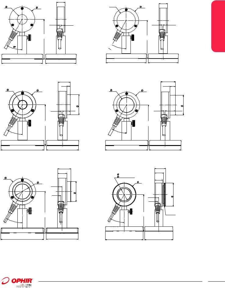
PE25-C / PE25BF-C |
|
|
|
|
21 |
24 |
62 |
|
|
7.5 |
10.5 |
|
ADJUSTABLE |
|
|
90-139 |
|
30° |
|
|
100 |
|
75 |
PE25BF-DIF-C |
|
28.5 |
|
|
7.5 |
20 |
62 |
|
|
|
47 |
|
7.5 |
18 |
|
ADJUSTABLE |
|
|
90-139 |
|
30° |
|
|
100 |
|
75 |
PE50BF-DIFH-C |
|
31 |
|
|
21.5 |
62 |
|
|
|
35 |
|
|
10.5 |
|
|
|
47 |
|
7.5 |
|
|
ADJUSTABLE |
|
|
90-139 |
|
30° |
|
|
100 |
|
75 |
PE50-C / PE50BF-C
 46
46
 30°
30°
|
21 |
62 |
|
7.5 |
10.5 |
ADJUSTABLE |
|
90-139 |
|
100 |
75 |
PE50BF-DIF-C / PE50-DIF-C |
35 |
|
|
|
13.5 |
35 |
62 |
|
|
|
47 |
|
7.5 |
24.5 |
|
ADJUSTABLE |
|
|
90-139 |
|
30° |
|
|
100 |
|
75 |
PE50BB-DIF-C |
28.5 |
|
|
||
33-(Diffuser In) |
23.5 |
|
|
|
|
46-(Diffuser Out) |
|
21 |
|
62 |
|
|
|
|
|
10.5 |
62 |
|
|
|
|
7.5 |
|
|
ADJUSTABLE |
Removable |
|
Diffuser |
|
|
90-139 |
Assembly |
|
|
|
3 |
|
|
0° |
|
|
100 |
|
75 |
1.2.3 Sensors
67
For latest updates please visit our website: www.ophiropt.com/photonics |
01.04.2014 |

1.2.3 Sensors
1.2.3 High Energy Pyroelectric Sensors
10µJ to 40J |
PE50-DIF-ER-C |
PE100BF-DIF-C |
||
Features |
DIFFUSER IN |
DIFFUSER OUT |
DIFFUSER IN |
DIFFUSER OUT |
|
|
|
|
|
ֺRemovable diffusers
ֺPE50-DIF-ER-C mainly for NIR lasers
ֺPE100BF-DIF-C for very large beams
ֺRep rates up to 10kHz
ֺMeasure lasers with pulse widths up to 20ms
Model |
|
PE50-DIF-ER-C |
|
|
|
|
|
|
|
|
PE100BF-DIF-C |
|
|
|
|
|
|
|
||||
Use |
|
Mainly for 1064nm, 2.1µm and 2.94µm |
|
|
|
|
Very large aperture |
|
|
|
|
|
|
|||||||||
|
|
|
|
|
|
|
|
|
|
|
|
|
|
|
|
|
|
|
||||
Diffuser |
Diffuser out |
|
|
|
Diffuser in |
|
|
|
Diffuser out |
|
|
|
Diffuser in |
|
|
|
||||||
Aperture mm |
|
φ46 |
|
|
|
|
φ33 |
|
|
|
|
|
φ96 |
|
|
|
|
φ85 |
|
|
|
|
Absorber Type |
|
Metallic |
|
|
|
Metallic with diffuser |
|
|
BF |
|
|
|
|
BF with diffuser |
|
|
||||||
Spectral Range µm (a) |
0.19 - 3 |
|
|
|
0.4 - 3 |
|
|
|
0.15 - 3 |
|
|
|
0.4 - 2.5 |
|
|
|
||||||
Surface Reflectivity % approx. |
50 |
|
|
|
|
50 |
|
|
|
|
20 |
|
|
|
|
50 |
|
|
|
|
||
Calibration Accuracy +/-% (a) |
3 |
|
|
|
|
3 |
|
|
|
|
3 |
|
|
|
|
3 |
|
|
|
|
||
Max Pulse Width Setting (c) |
|
2μs |
30μs |
500μs 1ms |
5ms |
2μs |
30μs |
500μs 1ms |
5ms |
|
1ms |
2ms |
5ms |
10ms |
20ms |
1ms |
2ms |
5ms |
10ms |
20ms |
||
Energy Scales |
|
10J to 10J to 10J to |
10J to |
10J to |
30J to 30J to 30J to |
30J to |
30J to |
|
10J to |
10J to |
10J to |
10J to |
10J to |
40J to |
40J to |
40J to |
40J to |
40J to |
||||
|
|
200µJ 200µJ 2mJ |
2mJ |
2mJ |
600μJ 600μJ 6mJ |
6mJ |
6mJ |
|
2mJ |
20mJ |
20mJ |
20mJ |
20mJ |
40mJ |
40mJ |
40mJ |
40mJ |
40mJ |
||||
Lowest Measurable Energy |
0.01 |
0.01 |
0.06 |
0.08 |
0.1 |
0.05 |
0.05 |
0.3 |
0.4 |
0.5 |
0.4 |
0.7 |
1.5 |
1.5 |
1.5 |
2 |
3 |
5 |
5 |
5 |
||
mJ (b, d) |
|
|
|
|
|
|
|
|
|
|
|
|
|
|
|
|
|
|
|
|
|
|
Max Pulse Width ms |
0.002 |
0.03 |
0.5 |
1 |
5 |
0.002 |
0.03 |
0.5 |
1 |
5 |
1 |
2 |
5 |
10 |
20 |
1 |
2 |
5 |
10 |
20 |
||
Maximum Pulse Rate pps |
|
10kHz 5kHz |
800Hz 400Hz 100Hz 10kHz 5kHz |
800Hz 400Hz 100Hz 200 |
100 |
50 |
35 |
25 |
200 |
100 |
50 |
35 |
25 |
|||||||||
Noise on Lowest Range µJ |
1 |
1 |
6 |
10 |
20 |
5 |
5 |
30 |
50 |
100 |
80 |
150 |
250 |
200 |
200 |
300 |
500 |
1000 |
600 |
600 |
||
Additional Error with |
|
±2% to ±2% |
±2% |
±2% |
±1% |
±2% to ±2% |
±2% |
±2% |
±1% |
|
|
|
|
|
±1% |
|
|
|
|
|||
Frequency % |
|
2kHz |
|
|
|
to |
2kHz |
|
|
|
to |
|
|
|
|
|
|
|
|
|
|
|
|
±4.5% |
|
|
|
80Hz |
±4.5% |
|
|
|
80Hz |
|
|
|
|
|
|
|
|
|
|
|
|
|
|
to5kHz |
|
|
|
|
to5kHz |
|
|
|
|
|
|
|
|
|
|
|
|
|
|
|
Linearity with Energy for > |
|
|
|
|
|
±1.5% |
|
|
|
|
|
|
|
|
|
±1% |
|
|
|
|
||
10% of full scale (b) |
|
|
|
|
|
|
|
|
|
|
|
|
|
|
|
|
|
|
|
|
|
|
Damage Threshold J/cm2 |
|
|
|
|
|
|
|
|
|
|
|
|
|
|
|
|
|
|
|
|
|
|
<100ns |
0.1 |
|
|
|
|
1.5 |
|
|
|
|
0.8 |
|
|
|
|
3 |
|
|
|
|
||
1µs |
0.2 |
|
|
|
|
3 |
|
|
|
|
1 |
|
|
|
|
3 |
|
|
|
|
||
300µs |
2 |
|
|
|
|
20 |
|
|
|
|
5 |
|
|
|
|
10 |
|
|
|
|
||
2ms |
6 |
|
|
|
|
60 |
|
|
|
|
10 |
|
|
|
|
25 |
|
|
|
|
||
Maximum Average Power W (d) |
|
15, 25 with optional heat sink |
40, 60 with optional heat sink |
15 |
|
|
|
|
40 |
|
|
|
|
|||||||||
Maximum Average Power |
20 |
|
|
|
|
500 |
|
|
|
|
20 |
|
|
|
|
500 |
|
|
|
|
||
Density W/cm2 |
|
|
|
|
|
|
|
|
|
|
|
|
|
|
|
|
|
|
|
|
|
|
Weight kg |
0.3 |
|
|
|
|
|
|
|
|
|
1.2 |
|
|
|
|
|
|
|
|
|
||
Version |
|
|
|
|
|
|
|
|
|
|
|
|
|
|
|
|
|
|
|
|
|
|
Part Number |
|
7Z02948 |
|
|
|
|
|
|
|
|
|
7Z02942 |
|
|
|
|
|
|
|
|
||
Notes: (a) |
|
Calibrated at 532nm and 1064nm |
Calibrated at 1064nm, |
|
|
|
Calibrated at 532nm |
|
|
Calibrated at 532nm, 1064nm and |
||||||||||||
|
|
only |
|
|
|
|
2100nm and 2940nm |
|
|
|
and 1064nm only |
|
|
1550nm only |
|
|
|
|||||
Notes: (b) With the "user threshold" setting set to minimum. For other settings, the spec is for >10% of full scale or greater than twice the "user threshold", whichever is greater.
The user threshold is available with Nova II, Vega, StarLite or Juno. For other meters, the threshold is set to minimum and the linearity spec is >10% of full scale. The PE-C series will only operate with Nova or Orion meters with an additional adapter Ophir P/N 7Z08272 (see page 70). The adapter can introduce up to 1% additional measurement error.
The user threshold feature allows adjustment of the internal threshold up to 25% of full scale if desired to avoid false triggering in noisy environments. The user threshold setting represents the approximate minimum energy for pulse widths below ~50% of the pulse width setting. For longer pulse widths, the actual minimum may be higher. For highest accuracy, it is recommended to zero the sensor against the meter the first time it is used with a particular meter. For further information, see the FAQs on our Website.
Notes: (c) With the Laserstar, Pulsar, USBI, Quasar and Nova/Orion with adapter only 2 of the 5 pulse width settings are available. For the PE50-DIF-ER-C, the 30µs and 1ms settings and for the PE100BF-DIF-C, the 1ms and 10ms settings.
Notes: (d) A shock absorbing mounting post is available for situations in which sensor is mounted on a surface subject to shock or vibration. This can prevent false triggering and allow working at lower minimum energies. Note however, that in this case the maximum average power will be reduced to 13W without heat sink and 25W with heat sink (see accessory pages 69-70 for heat sink and mounting post). Not available for model PE100BF-DIF-C.
PE50-DIF-ER-C
 33-(Diffuser In)
 46-(Diffuser Out)
 62
62
10.5
7.5
ADJUSTABLE 90-139
30°
100
28.5 |
PE100BF-DIF-C |
|
|
|
|
|
|
23.5 |
85-(Diffuser In) |
|
32.5 |
|
|
||
21 |
96-(Diffuser Out) |
|
24 |
85 |
|
Removable Diffuser |
|
|
|
||
|
|
125 |
Assembly |
|
|
|
|
|
62 |
|
|
|
|
|
12 |
|
Removable |
|
7 |
|
Diffuser |
|
|
|
Assembly |
ADJUSTABLE |
|
|
|
122-170 |
|
|
3 |
|
|
|
0° |
|
|
75 |
100 |
|
75 |
68
01.04.2014 |
|
For latest updates please visit our website: www.ophiropt.com/photonics |
|