


Freescale Semiconductor, Inc.
Freescale Semiconductor, Inc.
MSCAN Overview
CAN specification 2.0A defines an 11-bit Identifier; CAN specification 2.0B defines Identifiers with 11 bits (Standard) and 29 bits (Extended).
1.3 MSCAN Overview
The MSCAN modules are Motorola-specific implementations of CAN controllers for the CAN 2.0B protocol. These are highly efficient CAN controller modules, optimized for real-time performance, that incorporate important features for predictable CAN network traffic.
The basic features of the MSCAN are:
•Modular architecture
•Implementation of the CAN protocol - Version 2.0A/B
—Standard and extended data frames
—0 - 8 bytes data length
—Programmable bit rate up to 1 Mbps1
—Support for remote frames
•Double-buffered receive storage scheme
•Triple-buffered transmit storage scheme with internal prioritization using a “local priority” concept
•Flexible maskable Identifier filter supports two full-size extended Identifier filters (two 32-bit), four 16-bit filters, or eight 8-bit filters
•Programmable wake-up functionality with integrated low-pass filter
•Programmable loopback mode supports self-test operation
•Separate signalling and interrupt capabilities for all CAN receiver and transmitter error states (Warning, Error Passive, Bus-Off)
•Programmable MSCAN clock source (either IP Bus clock or crystal oscillator output)
•Three low power modes:
—SLEEP
—Soft RESET
—Power Down
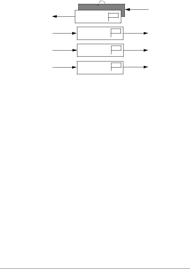
The three transmit message buffers and one double-buffered receive message buffer of MSCAN are organized as shown in Figure 1-1.
1. Depending on the actual bit timing and the clock jitter of the PLL.
MOTOROLA Overview 1-3
For More Information On This Product,
Go to: www.freescale.com
Freescale Semiconductor, Inc.
Freescale Semiconductor, Inc.
Overview
CPU bus |
MSCAN |
RxBG 
RxFG RXF
TXEx
Tx Buffer 1
TXEx
Tx Buffer 2
TXEx
Tx Buffer 3
Figure 1-1. MSCAN Message Buffers Organization
1.3.1 Message Transmission
All three transmit buffers have 13-byte data structure.
To transmit a message, the available MSCAN transmit buffer shall be identified, which is indicated by a set Transmit Buffer Empty (TXEx) flag. If the Tx Buffer is available, the Identifier, control bits and data contents are then stored in one of the transmit buffers, and the buffer is flagged as ready for transmission by clearing the associated TXEx flag. The MSCAN then schedules the message for transmission and signals the successful transmission of the buffer by setting the associated TXEx flag. If not masked, the send ISR is generated when TXEx is set and is used by the driver to re-load the buffer.
In case more than one buffer is scheduled for transmission when the CAN bus becomes available for arbitration, the MSCAN uses the local priority setting for the three buffers to determine the transmission order. The local priority reflects the priority of this particular message relative to the set of messages being transmitted from this node. The lowest binary priority value is defined to be the highest priority.
1.3.2 Message Receiving
The received messages are stored in a two-stage input FIFO. The two message buffers are alternatively mapped into a single memory area. While the background buffer (RxBG) is exclusively associated with the MSCAN, the foreground buffer (RxFG) is addressable by the CPU.
The Receiver Full flag (RXF) signals the status of the foreground receive buffer. When the buffer contains a correctly-received message with the matching Identifier, this flag is set.
1-4 |
DSP56800/MSCAN Driver User Manual |
MOTOROLA |
For More Information On This Product,
Go to: www.freescale.com