

Serial Peripheral Interface
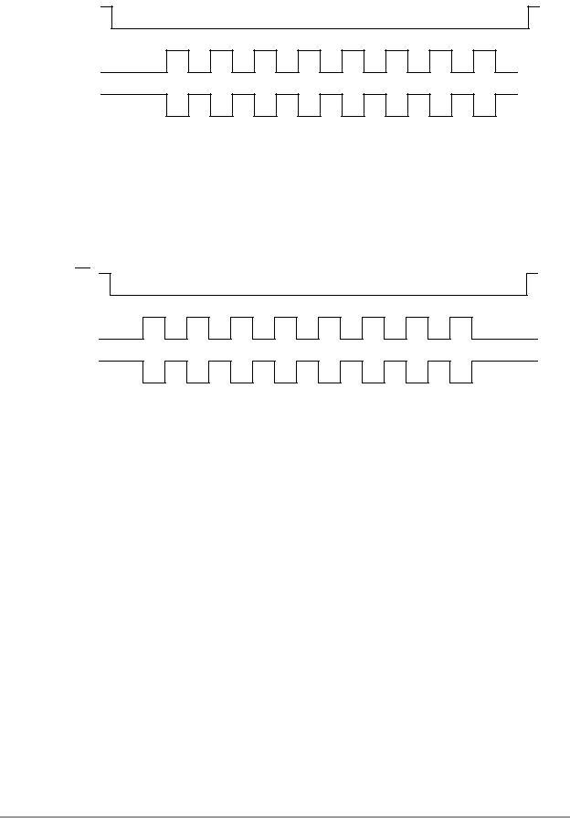
SS
(to slave)
SCK (CPL=0)
SCK (CPL=1)
MOSI (from master)
MISO (from slave)
SS
(to slave)
SCK (CPL=0)
SCK (CPL=1)
MOSI (from master)
MISO (from slave)
|
|
MSB |
|
|
|
|
|
|
LSB |
|
|
|
|
|
|
|
|
|
|
|
|
|
|
|
|
|
|
|
|
|
|
|
|
|
|
|
|||||
|
MSB |
|
|
|
|
|
|
LSB |
* |
|
|
|
|
|
|
|
|
|
|
|
|
|
|||||
|
|
|
|
|
|
|
|
|
|
|
|
|
|
|
* Not defined, but normally MSB of word just received |
|
|
|
|
|
AA1383 |
||||||
Figure 7-3. SPI Transfer with CPH = 0
|
|
MSB |
|
|
|
|
|
|
LSB |
|
|
|
|
|
|
|
|
|
|
|
|
|
|
|
|
|
|
|
|
|
|
|
|
|
|
||||||
|
* |
MSB |
|
|
|
|
|
|
LSB |
|
|
||
|
|
|
|
|
|
|
|
|
|||||
|
|
|
|
|
|
|
|
|
|
|
|
|
|
* Not defined, but normally LSB of word previously transmitted |
|
|
|
|
AA1384 |
||||||||
Figure 7-4. SPI Transfer with CPH = 1
7.2 SPI Programming Model
Each SPI peripheral provides the following registers:
•SPI control register (SPCR)
•SPI status register (SPSR)
•SPI data register (SPDR)
These registers are shown in Figure 7-5 on page 7-5. The descriptions of the registers in the following paragraphs apply equally to the corresponding registers on SPI0 and SPI1.
7-4 |
DSP56824 User’s Manual |
|

SPI Programming Model
SPCR1— X:$FFE6 |
15 |
14 |
13 |
12 |
11 |
10 |
9 |
8 |
7 |
6 |
5 |
4 |
3 |
2 |
1 |
0 |
SPCR0— X:$FFE2 |
|
|
|
|
|
|
|
SPR |
SPIE |
SPE |
WOM |
MST |
CPL |
CPH |
SPR |
SPR |
SPI Control Register |
|
|
|
|
|
|
|
|||||||||
* |
* |
* |
* |
* |
* |
* |
2 |
|
|
|
|
|
|
1 |
0 |
|
Reset = $0000 |
|
|
|
|
|
|
||||||||||
|
|
|
|
|
|
|
|
|
|
|
|
|
|
|
|
|
Read/Write |
|
|
|
|
|
|
|
|
|
|
|
|
|
|
|
|
|
|
|
|
|
|
|
|
|
|
|
|
|
|
|
|
|
|
|
|
|
|
|
|
|
|
|
|
|
|
|
|
|
|
SPSR1— X:$FFE5 |
15 |
14 |
13 |
12 |
11 |
10 |
9 |
8 |
7 |
6 |
5 |
4 |
3 |
2 |
1 |
0 |
SPSR0— X:$FFE1 |
|
|
|
|
|
|
|
|
|
|
|
|
|
|
|
|
|
|
|
|
|
|
|
|
SPIF |
WC |
|
MDF |
|
|
|
|
|
SPI Status Register |
|
|
|
|
|
|
|
|
|
|
|
|
|
|||
* |
* |
* |
* |
* |
* |
* |
* |
|
OL |
* |
|
* |
* |
* |
* |
|
Reset = $0000 |
|
|
||||||||||||||
|
|
|
|
|
|
|
|
|
|
|
|
|
|
|
|
|
Read-Only |
|
|
|
|
|
|
|
|
|
|
|
|
|
|
|
|
|
|
|
|
|
|
|
|
|
|
|
|
|
|
|
|
|
|
|
|
|
|
|
|
|
|
|
|
|
|
|
|
|
|
SPDR1— X:$FFE4 |
15 |
14 |
13 |
12 |
11 |
10 |
9 |
8 |
7 |
6 |
5 |
4 |
3 |
2 |
1 |
0 |
SPDR0— X:$FFE0 |
|
|
|
High byte |
|
|
|
|
|
|
Low byte |
|
|
|
||
SPI Data Register |
|
|
|
|
|
|
|
|
|
|
|
|
||||
|
|
(Always reads as $00) |
|
|
|
|
(Contains 8-bit data) |
|
|
|||||||
Reset = Uninitialized |
|
|
|
|
|
|
|
|
||||||||
|
|
|
|
|
|
|
|
|
|
|
|
|
|
|
|
|
Read/Write |
|
|
|
|
|
|
|
|
|
|
|
|
|
|
|
|
|
|
|
|
|
|
|
|
|
|
|
|
|
|
|
|
|
|
|
|
|
|
|
|
|
|
|
|
|
|
|
|
|
|
* Indicates reserved bits, written as 0 for future compatibility
SPI Interrupt Vectors:
SPI1 Serial System
P:$0028
SPI0 Serial System
P:$002A
Enabling SPI Interrupts in the IPR:
SPI1: Set bit 12 to 1 in the IPR (X:$FFFB).
SPI0: Set bit 13 to 1 in the IPR (X:$FFFB).
AA0147
Figure 7-5. SPI Programming Model
NOTE:
To use SPI0, the CC[3:0] bits in the PCC register must be correctly set. To use SPI1, the CC[7:4] bits in the PCC register must be correctly set. See Section 7.5, “Configuring Port C for SPI Functionality,” for more information.
Serial Peripheral Interface |
7-5 |