

Program Definition and Initialization Phase
3 Sonar Implementation on the DSP56824
As shown in previous sections, all the sonar-specific algorithms are implemented on the DSP56824. The main program on the DSP follows the general steps presented in Figure 2 on page 4.
Code Listing 1 presents the main program sequence of sonar implementation. First, the general data structures used by the main program and the subsequent routines are defined, and the DSP initialization is made. In the Section 3.1 we describe this initial phase of the program.
The main program incorporates into an infinite loop all the routines developed for the target detection, distance calculation and communicates the results to the host.
|
Code Listing 1. Sonar main program on DSP |
|
|
Defines_and_Init |
; here are the general data structures defines |
||
|
|
; and the Sonar initialization |
|
main |
|
|
|
jsr |
Gen_Signal |
|
|
jsr |
Read_ADC |
|
|
jsr |
Moving_Average |
|
|
jsr |
Seek_MAX |
|
|
jsr |
Calc_Position |
|
|
jsr |
Gen_Sincro |
|
|
move |
angle,y1 |
|
|
jsr |
Out_y1 |
|
|
move |
distance,y1 |
|
|
jsr |
Out_y1 |
|
|
jsr |
rotate_motor |
|
|
jmp |
main |
|
|
|
|
|
|
Generation of the emitted signal is the first step performed by the sonar program - the ‘Gen_Signal’ routine. Next, the DSP commands the analog-to-digital converter to fill a 2048-word buffer with samples from the received echo signal. This is accomplished by the ‘Read_ADC’ procedure.
Actual calculation of the distance to a target is performed on the data buffer written during the ‘Read_ADC’ step. First, the received signal is filtered using a Moving Average type of low-pass digital filter. Next, we look for the maximum value on the buffer. Its relative position will then be represented in millimeters and stored into the ‘distance’ variable. The ‘Calc_Position’ results in the angular coordinate of the target—the ‘angle’ parameter.
At this point, the DSP has a complete set of results to be sent to the host computer through the serial data link. It starts the synchronization procedure, ‘Gen_Sincro’, which waits for the host to acknowledge it is ready to receive the results and at the same time ensures a correct data transaction on the serial interface.
After the correct synchronization step the two target coordinates (‘distance’ and ‘angle’) are sent to the host computer for display.
Finally, the stepper motor is commanded for a 1.8 degree rotation of the transducer platform, and the main sonar program loops back to the next target detection iteration.
Extensive implementation details of all the above routines will be given in the following sub-sections.
3.1Program Definition and Initialization Phase
All the general program parameters and variables are defined in this section: peripheral and core DSP registers used by the sonar program, temporary values, sonar functional parameters, constants, and so on.
Sonar Implementation on the DSP56824 |
7 |
Code Listing 2. General Program Defines
; Program defines |
|
|
|
define |
ipr |
’x:$fffb’ |
; Interrupt priority register |
define |
bcr |
’x:$fff9’ |
; Bus control register |
define |
pcr1 |
’x:$fff3’ |
; PLL control register 1 |
define |
pcr0 |
’x:$fff2’ |
; PLL control register 0 |
define |
pbd |
’x:$ffec’ |
; Port B data register |
define |
pbddr |
’x:$ffeb’ |
; Port B data direction register |
define |
pbint |
’x:$ffea’ |
; Port B Interrupt register |
define |
pcd |
’x:$ffef’ |
; Port C data register |
define |
pcddr |
’x:$ffee’ |
; Port C data direction register |
define |
pcc |
’x:$ffed’ |
; Port C control register |
define |
spcr1 |
’x:$ffe6’ |
; spi 1 control register |
define |
spsr1 |
’x:$ffe5’ |
; spi 1 status register |
define |
spdr1 |
’x:$ffe4’ |
; spi 1 data register |
; Variables used in program to retain temporary values, |
|||
;; results and to perform software loops. |
|
||
define |
go |
’x:$0’ |
|
define |
loopc1 |
’x:$1’ |
|
define |
loopc2 |
’x:$2’ |
|
define |
save_r0 |
’x:$3’ |
|
define |
save_m |
’x:$4’ |
|
define |
leftcount |
’x:$5’ |
|
define |
rightcount |
’x:$6’ |
|
define |
angle |
’x:$7’ |
|
define |
distance |
’x:$8’ |
|
; Program equates |
|
|
|
SPIF |
equ |
$0080 |
; SPIO Interrupt complete flag |
dummy |
equ |
$0000 |
; dummy value to write |
pc7 |
equ |
$0080 |
; port C bit 7 |
WRITEUP |
equ |
$0080 |
; write upper instruction byte |
READ |
equ |
$0000 |
; read command |
PLL_DIV |
equ |
19 |
; PLL Feedback Multiplier |
dim |
equ |
2048 |
; receive buffer dimension |
dim_mot_buf |
equ |
4 |
; the dimension of command motor |
|
|
|
;; buffer words |
no_detection |
equ |
0 |
; constant used to indicate that |
|
|
|
;; no object is detected |
noise_level |
equ |
6 |
; maximum noise level |
av_points |
equ |
20 |
; the number of coefficients for |
|
|
|
;; moving average filter |
no_wave |
equ |
40 |
; the number of periods for the |
|
|
|
;; emitted signal |
|
|
|
|
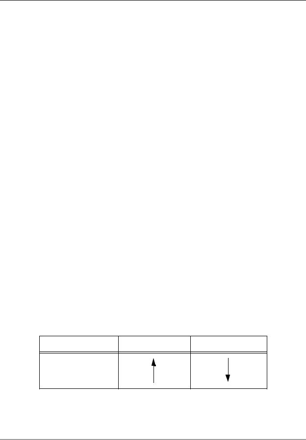
In the next sequence of code, we define a circular buffer for the stepper motor command. In order to perform a 0.9 degrees one-step rotation, the stepper we used needs a two-bit input code explained in Table 1.
Table 1. Stepper Motor Command Sequence
GPIO Pin Numbers: 14,15 One Step Left Rotation One Step Right Rotation
1 1
0 1
0 0
1 0
8 |
Simple Real-Time Sonar with the DSP56824 |
|

Program Definition and Initialization Phase
Depending on the current configuration of the two command lines (GPIO Pin 14 and 15), the next step rotation will be commanded by following the corresponding direction shown in Table 1 (see also Figure 5 on page 6). For example, if the current command lines configuration is ‘01’ and we need to perform a one step right rotation of the stepper motor, the next sequence on the GPIO lines 14, 15 needs to be: ‘00’.
The motor command data structure implements a circular buffer, which will be scanned upwards or downwards, depending on the rotation type needed. The command is shown in the Code Listing 3.
Code Listing 3. Stepper Motor Command Data Structure
org x:$1000
; this circular buffer retains the command words for the motor
buffer |
m,dim_mot_buf |
pas |
|
dc |
$0000 |
dc |
$8000 |
dc |
$c000 |
dc |
$4000 |
endbuf |
|
|
|
Further on, the DSP stack initialization, along with the PLL, GPIO, and interrupts setup is made:
Sonar Implementation on the DSP56824 |
9 |

Code Listing 4. Main Program Initialization Sequence
|
org |
x:$2000 |
; receive buffer |
|
|
|
buffer |
m,dim |
m_buf |
ds |
dim |
|
endbuf |
|
|
org |
p:$0000 |
|
jmp |
Start |
|
org |
p:$0014 |
|
jsr |
Irqa_ISR |
|
org |
p:$0100 |
Start |
move |
#$40,sp |
|
||
|
move |
#$0000,bcr |
|
move |
#(PLL_DIV-1)<<5,pcr0 |
|
bfset |
#$4208,pcr1 |
; Delay to meet the pll lock setup time
move |
#$1fff,lc |
do |
lc,delay1 |
nop |
|
nop |
|
delay1 |
|
move |
#$1fff,lc |
do |
lc,delay2 |
nop |
|
nop |
|
delay2 |
|
move |
#$F000,pbddr |
move |
#$8000,ipr |
bfset |
#$0100,sr |
bfclr |
#$0200,sr |
move |
#dim,m01 |
move |
#1,n |
move |
#pas,save_r0 |
move |
#100,x0 |
move |
x0,leftcount |
move |
#0,x0 |
move |
x0,rightcount |
;start of program
;Port B GPIO Interrupt
;Starting location of this ;; program
;Set stack pointer to first ;; location
;; after page 0
;Initialize BCR for zero wait ;; states
;Configure PLL feedback divider
;3.6864 MHz * 19 = 70.0416 MHz
;Enable PLL using oscillator ;;clock—PLLE=1,PS1=1,VCS0=1
;Configure GPIO pins
;Enable GPIO interrupts
;Enable all level of interrupts
The routine which programs SPI on port C to communicate with host computer is given below. When the SPI is configured as a master, the software selects one of the eight different bit rates for the clock. The routine also configures the MAX3100 UART (universal asynchronous receiver transmitter) used as RS-232 interface.
10 |
Simple Real-Time Sonar with the DSP56824 |
|