

- •About This Book
- •1.1 DSP56800 Family Architecture
- •1.1.1 Core Overview
- •1.1.2 Peripheral Blocks
- •1.1.3 Family Members
- •1.2 Introduction to Digital Signal Processing
- •1.3 Summary of Features
- •1.4 For the Latest Information
- •2.1 Core Block Diagram
- •2.1.1 Data Arithmetic Logic Unit (ALU)
- •2.1.2 Address Generation Unit (AGU)
- •2.1.3 Program Controller and Hardware Looping Unit
- •2.1.4 Bus and Bit-Manipulation Unit
- •2.1.5 On-Chip Emulation (OnCE) Unit
- •2.1.6 Address Buses
- •2.1.7 Data Buses
- •2.2 Memory Architecture
- •2.3 Blocks Outside the DSP56800 Core
- •2.3.1 External Data Memory
- •2.3.2 Program Memory
- •2.3.3 Bootstrap Memory
- •2.3.4 IP-BUS Bridge
- •2.3.5 Phase Lock Loop (PLL)
- •2.4 DSP56800 Core Programming Model
- •3.1 Overview and Architecture
- •3.1.1 Data ALU Input Registers (X0, Y1, and Y0)
- •3.1.2 Data ALU Accumulator Registers
- •3.1.3 Multiply-Accumulator (MAC) and Logic Unit
- •3.1.4 Barrel Shifter
- •3.1.5 Accumulator Shifter
- •3.1.6 Data Limiter and MAC Output Limiter
- •3.2 Accessing the Accumulator Registers
- •3.2.1 Accessing an Accumulator by Its Individual Portions
- •3.2.2 Accessing an Entire Accumulator
- •3.2.2.1 Accessing for Data ALU Operations
- •3.2.2.2 Writing an Accumulator with a Small Operand
- •3.2.2.3 Extension Registers as Protection Against Overflow
- •3.2.2.4 Examples of Writing the Entire Accumulator
- •3.2.3 General Integer Processing
- •3.2.3.1 Writing Integer Data to an Accumulator
- •3.2.3.2 Reading Integer Data from an Accumulator
- •3.2.4 Using 16-Bit Results of DSP Algorithms
- •3.2.5 Saving and Restoring Accumulators
- •3.2.6 Bit-Field Operations on Integers in Accumulators
- •3.2.7 Converting from 36-Bit Accumulator to 16-Bit Portion
- •3.3 Fractional and Integer Data ALU Arithmetic
- •3.3.1 Interpreting Data
- •3.3.2 Data Formats
- •3.3.2.1 Signed Fractional
- •3.3.2.2 Unsigned Fractional
- •3.3.2.3 Signed Integer
- •3.3.2.4 Unsigned Integer
- •3.3.3 Addition and Subtraction
- •3.3.4 Logical Operations
- •3.3.5 Multiplication
- •3.3.5.1 Fractional Multiplication
- •3.3.5.2 Integer Multiplication
- •3.3.6 Division
- •3.3.7 Unsigned Arithmetic
- •3.3.7.1 Conditional Branch Instructions for Unsigned Operations
- •3.3.7.2 Unsigned Multiplication
- •3.3.8 Multi-Precision Operations
- •3.3.8.1 Multi-Precision Addition and Subtraction
- •3.3.8.2 Multi-Precision Multiplication
- •3.4 Saturation and Data Limiting
- •3.4.1 Data Limiter
- •3.4.2 MAC Output Limiter
- •3.4.3 Instructions Not Affected by the MAC Output Limiter
- •3.5 Rounding
- •3.5.1 Convergent Rounding
- •3.5.2 Two’s-Complement Rounding
- •3.6 Condition Code Generation
- •3.6.1 36-Bit Destinations—CC Bit Cleared
- •3.6.2 36-Bit Destinations—CC Bit Set
- •3.6.3 20-Bit Destinations—CC Bit Cleared
- •3.6.4 20-Bit Destinations—CC Bit Set
- •3.6.5 16-Bit Destinations
- •3.6.6 Special Instruction Types
- •3.6.7 TST and TSTW Instructions
- •3.6.8 Unsigned Arithmetic
- •4.1 Architecture and Programming Model
- •4.1.1 Address Registers (R0-R3)
- •4.1.2 Stack Pointer Register (SP)
- •4.1.3 Offset Register (N)
- •4.1.4 Modifier Register (M01)
- •4.1.5 Modulo Arithmetic Unit
- •4.1.6 Incrementer/Decrementer Unit
- •4.2 Addressing Modes
- •4.2.1 Register-Direct Modes
- •4.2.1.1 Data or Control Register Direct
- •4.2.1.2 Address Register Direct
- •4.2.2 Address-Register-Indirect Modes
- •4.2.2.1 No Update: (Rn), (SP)
- •4.2.2.2 Post-Increment by 1: (Rn)+, (SP)+
- •4.2.2.3 Post-Decrement by 1: (Rn)-, (SP)-
- •4.2.2.4 Post-Update by Offset N: (Rn)+N, (SP)+N
- •4.2.2.5 Index by Offset N: (Rn+N), (SP+N)
- •4.2.2.6 Index by Short Displacement: (SP-xx), (R2+xx)
- •4.2.2.7 Index by Long Displacement: (Rn+xxxx), (SP+xxxx)
- •4.2.3 Immediate Data Modes
- •4.2.3.1 Immediate Data: #xxxx
- •4.2.3.2 Immediate Short Data: #xx
- •4.2.4 Absolute Addressing Modes
- •4.2.4.1 Absolute Address (Extended Addressing): xxxx
- •4.2.4.2 Absolute Short Address (Direct Addressing): <aa>
- •4.2.4.3 I/O Short Address (Direct Addressing): <pp>
- •4.2.5 Implicit Reference
- •4.2.6 Addressing Modes Summary
- •4.3 AGU Address Arithmetic
- •4.3.1 Linear Arithmetic
- •4.3.2 Modulo Arithmetic
- •4.3.2.1 Modulo Arithmetic Overview
- •4.3.2.2 Configuring Modulo Arithmetic
- •4.3.2.3 Supported Memory Access Instructions
- •4.3.2.4 Simple Circular Buffer Example
- •4.3.2.5 Setting Up a Modulo Buffer
- •4.3.2.6 Wrapping to a Different Bank
- •4.3.2.7 Side Effects of Modulo Arithmetic
- •4.3.2.7.1 When a Pointer Lies Outside a Modulo Buffer
- •4.3.2.7.2 Restrictions on the Offset Register
- •4.3.2.7.3 Memory Locations Not Available for Modulo Buffers
- •4.4 Pipeline Dependencies
- •5.1 Architecture and Programming Model
- •5.1.1 Program Counter
- •5.1.2 Instruction Latch and Instruction Decoder
- •5.1.3 Interrupt Control Unit
- •5.1.4 Looping Control Unit
- •5.1.5 Loop Counter
- •5.1.6 Loop Address
- •5.1.7 Hardware Stack
- •5.1.8 Status Register
- •5.1.8.1 Carry (C)—Bit 0
- •5.1.8.2 Overflow (V)—Bit 1
- •5.1.8.3 Zero (Z)—Bit 2
- •5.1.8.4 Negative (N)—Bit 3
- •5.1.8.5 Unnormalized (U)—Bit 4
- •5.1.8.6 Extension (E)—Bit 5
- •5.1.8.7 Limit (L)—Bit 6
- •5.1.8.8 Size (SZ)—Bit 7
- •5.1.8.9 Interrupt Mask (I1 and I0)—Bits 8–9
- •5.1.8.10 Reserved SR Bits— Bits 10–14
- •5.1.8.11 Loop Flag (LF)—Bit 15
- •5.1.9 Operating Mode Register
- •5.1.9.1 Operating Mode Bits (MB and MA)—Bits 1–0
- •5.1.9.2 External X Memory Bit (EX)—Bit 3
- •5.1.9.3 Saturation (SA)—Bit 4
- •5.1.9.4 Rounding Bit (R)—Bit 5
- •5.1.9.5 Stop Delay Bit (SD)—Bit 6
- •5.1.9.6 Condition Code Bit (CC)—Bit 8
- •5.1.9.7 Nested Looping Bit (NL)—Bit 15
- •5.1.9.8 Reserved OMR Bits—Bits 2, 7 and 9–14
- •5.2 Software Stack Operation
- •5.3 Program Looping
- •5.3.1 Repeat (REP) Looping
- •5.3.2 DO Looping
- •5.3.3 Nested Hardware DO and REP Looping
- •5.3.4 Terminating a DO Loop
- •6.1 Introduction to Moves and Parallel Moves
- •6.2 Instruction Formats
- •6.3 Programming Model
- •6.4 Instruction Groups
- •6.4.1 Arithmetic Instructions
- •6.4.2 Logical Instructions
- •6.4.3 Bit-Manipulation Instructions
- •6.4.4 Looping Instructions
- •6.4.5 Move Instructions
- •6.4.6 Program Control Instructions
- •6.5 Instruction Aliases
- •6.5.1 ANDC, EORC, ORC, and NOTC Aliases
- •6.5.2 LSLL Alias
- •6.5.3 ASL Alias
- •6.5.4 CLR Alias
- •6.5.5 POP Alias
- •6.6 DSP56800 Instruction Set Summary
- •6.6.1 Register Field Notation
- •6.6.2 Using the Instruction Summary Tables
- •6.6.3 Instruction Summary Tables
- •6.7 The Instruction Pipeline
- •6.7.1 Instruction Processing
- •6.7.2 Memory Access Processing
- •7.1 Reset Processing State
- •7.2 Normal Processing State
- •7.2.1 Instruction Pipeline Description
- •7.2.2 Instruction Pipeline with Off-Chip Memory Accesses
- •7.2.3 Instruction Pipeline Dependencies and Interlocks
- •7.3 Exception Processing State
- •7.3.1 Sequence of Events in the Exception Processing State
- •7.3.2 Reset and Interrupt Vector Table
- •7.3.3 Interrupt Priority Structure
- •7.3.4 Configuring Interrupt Sources
- •7.3.5 Interrupt Sources
- •7.3.5.1 External Hardware Interrupt Sources
- •7.3.5.2 DSP Core Hardware Interrupt Sources
- •7.3.5.3 DSP Core Software Interrupt Sources
- •7.3.6 Interrupt Arbitration
- •7.3.7 The Interrupt Pipeline
- •7.3.8 Interrupt Latency
- •7.4 Wait Processing State
- •7.5 Stop Processing State
- •7.6 Debug Processing State
- •8.1 Useful Instruction Operations
- •8.1.1 Jumps and Branches
- •8.1.1.1 JRSET and JRCLR Operations
- •8.1.1.2 BR1SET and BR1CLR Operations
- •8.1.1.3 JR1SET and JR1CLR Operations
- •8.1.1.4 JVS, JVC, BVS, and BVC Operations
- •8.1.1.5 Other Jumps and Branches on Condition Codes
- •8.1.2 Negation Operations
- •8.1.2.1 NEGW Operation
- •8.1.2.2 Negating the X0, Y0, or Y1 Data ALU registers
- •8.1.2.3 Negating an AGU register
- •8.1.2.4 Negating a Memory Location
- •8.1.3 Register Exchanges
- •8.1.4 Minimum and Maximum Values
- •8.1.4.1 MAX Operation
- •8.1.4.2 MIN Operation
- •8.1.5 Accumulator Sign Extend
- •8.1.6 Unsigned Load of an Accumulator
- •8.2.2 General 16-Bit Shifts
- •8.2.3 General 32-Bit Arithmetic Right Shifts
- •8.2.5 Arithmetic Shifts by a Fixed Amount
- •8.2.5.1 Right Shifts (ASR12–ASR20)
- •8.2.5.2 Left Shifts (ASL16–ASL19)
- •8.3 Incrementing and Decrementing Operations
- •8.4 Division
- •8.4.1 Positive Dividend and Divisor with Remainder
- •8.4.2 Signed Dividend and Divisor with No Remainder
- •8.4.3 Signed Dividend and Divisor with Remainder
- •8.4.4 Algorithm Examples
- •8.4.5 Overflow Cases
- •8.5 Multiple Value Pushes
- •8.6 Loops
- •8.6.1 Large Loops (Count Greater Than 63)
- •8.6.2 Variable Count Loops
- •8.6.3 Software Loops
- •8.6.4 Nested Loops
- •8.6.4.1 Recommendations
- •8.6.4.2 Nested Hardware DO and REP Loops
- •8.6.4.3 Comparison of Outer Looping Techniques
- •8.6.5 Hardware DO Looping in Interrupt Service Routines
- •8.6.6 Early Termination of a DO Loop
- •8.7 Array Indexes
- •8.7.1 Global or Fixed Array with a Constant
- •8.7.2 Global or Fixed Array with a Variable
- •8.7.3 Local Array with a Constant
- •8.7.4 Local Array with a Variable
- •8.7.5 Array with an Incrementing Pointer
- •8.8 Parameters and Local Variables
- •8.9 Time-Critical DO Loops
- •8.10 Interrupts
- •8.10.1 Setting Interrupt Priorities in Software
- •8.10.1.1 High Priority or a Small Number of Instructions
- •8.10.1.2 Many Instructions of Equal Priority
- •8.10.1.3 Many Instructions and Programmable Priorities
- •8.10.2 Hardware Looping in Interrupt Routines
- •8.10.3 Identifying System Calls by a Number
- •8.11 Jumps and JSRs Using a Register Value
- •8.12 Freeing One Hardware Stack Location
- •8.13 Multitasking and the Hardware Stack
- •8.13.1 Saving the Hardware Stack
- •8.13.2 Restoring the Hardware Stack
- •9.1 Combined JTAG and OnCE Interface
- •9.2 JTAG Port
- •9.2.1 JTAG Capabilities
- •9.2.2 JTAG Port Architecture
- •9.3 OnCE Port
- •9.3.1 OnCE Port Capabilities
- •9.3.2 OnCE Port Architecture
- •9.3.2.1 Command, Status, and Control
- •9.3.2.2 Breakpoint and Trace
- •9.3.2.3 Pipeline Save and Restore
- •9.3.2.4 FIFO History Buffer
- •A.1 Notation
- •A.2 Programming Model
- •A.3 Addressing Modes
- •A.4 Condition Code Computation
- •A.4.1 The Condition Code Bits
- •A.4.1.1 Size (SZ)—Bit 7
- •A.4.1.2 Limit (L)—Bit 6
- •A.4.1.3 Extension in Use (E)—Bit 5
- •A.4.1.4 Unnormalized (U)—Bit 4
- •A.4.1.5 Negative (N)—Bit 3
- •A.4.1.6 Zero (Z)—Bit 2
- •A.4.1.7 Overflow (V)—Bit 1
- •A.4.1.8 Carry (C)—Bit 0
- •A.4.2 Effects of the Operating Mode Register’s SA Bit
- •A.4.3 Effects of the OMR’s CC Bit
- •A.4.4 Condition Code Summary by Instruction
- •A.5 Instruction Timing
- •A.6 Instruction Set Restrictions
- •A.7 Instruction Descriptions
- •B.1 Benchmark Code
- •B.1.1 Real Correlation or Convolution (FIR Filter)
- •B.1.2 N Complex Multiplies
- •B.1.3 Complex Correlation Or Convolution (Complex FIR)
- •B.1.4 Nth Order Power Series (Real, Fractional Data)
- •B.1.5 N Cascaded Real Biquad IIR Filters (Direct Form II)
- •B.1.6 N Radix 2 FFT Butterflies
- •B.1.7 LMS Adaptive Filter
- •B.1.7.1 Single Precision
- •B.1.7.2 Double Precision
- •B.1.7.3 Double Precision Delayed
- •B.1.8 Vector Multiply-Accumulate
- •B.1.9 Energy in a Signal
- •B.1.10 [3x3][1x3] Matrix Multiply
- •B.1.11 [NxN][NxN] Matrix Multiply
- •B.1.12 N Point 3x3 2-D FIR Convolution
- •B.1.13 Sine-Wave Generation
- •B.1.13.1 Double Integration Technique
- •B.1.13.2 Second Order Oscillator
- •B.1.14 Array Search
- •B.1.14.1 Index of the Highest Signed Value
- •B.1.14.2 Index of the Highest Positive Value
- •B.1.15 Proportional Integrator Differentiator (PID) Algorithm
Fractional and Integer Data ALU Arithmetic
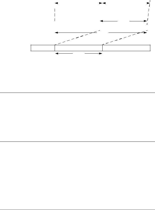
Signed Integer
Input Operands
Signed
Intermediate
Multiplier Result
|
|
Input Operand 1 |
|
|
Input Operand 2 |
||||||
|
|
|
|
||||||||
s |
|
|
|
|
s |
|
|
|
|
||
|
|
|
|
|
|
|
|
|
|
|
|
|
|
|
|
|
|
|
|
|
|
|
|
|
|
|
16 Bits |
|
|
|
|
|
16 Bits |
|
|
|
|
|
|
|
|
|
|
||||
16 Bits
|
|
|
|
|
s |
|
|
|
0 |
|
|
|
|
|
31 Bits
S Ext.
Signed Integer |
EXP |
MSP |
Unchanged |
Output |
16 Bits
AA0044
Figure 3-12. Integer Multiplication (IMPY)
At other times it is necessary to maintain the full 32-bit precision of an integer multiplication. To obtain integer results, an MPY instruction is used, immediately followed by an ASR instruction. The 32-bit long integer result is then correctly located into the MSP and LSP of an accumulator with correct sign extension in the extension register of the same accumulator (see Example 3-9).
Example 3-9. Multiplying Two Signed Integer Values with Full Precision
MPY |
X0,Y0,A |
; Generates correct answer shifted |
|
|
; 1 bit to the left |
ASR |
A |
; Leaves Correct 32-bit Integer |
|
|
; Result in the A Accumulator |
|
|
; and the A2 register contains |
|
|
; correct sign extension |
|
|
|
When a multiply-accumulate is performed on a set of integer numbers, there is a faster way for generating the result than performing an ASR instruction after each multiply. The technique is to use fractional multiply-accumulates for the bulk of the computation and to then convert the final result back to integer. See Example 3-10.
Example 3-10. Fast Integer MACs using Fractional Arithmetic
MOVE |
|
|
X:(R0)+,Y0 |
X:(R3)+,X0 |
DO |
#N,LABEL |
|
|
|
MAC |
X0,Y0,A |
X:(R0)+,Y0 |
X:(R3)+,X0 |
|
LABEL |
|
|
|
|
ASR |
A |
; Convert to Integer only after MACs are |
||
|
|
; completed |
|
|
|
|
|
|
|
3.3.6 Division
Fractional and integer division of both positive and signed values is supported using the DIV instruction. The dividend (numerator) is a 32-bit fractional or 31-bit integer value, and the divisor (denominator) is a 16-bit fractional or integer value, respectively. See Section 8.4, “Division,” on page 8-13 for a complete discussion of division.
Data Arithmetic Logic Unit |
3-21 |