

Задани на лабораторные работы. ПРК / Professional Microsoft Robotics Developer Studio
.pdfwww.it-ebooks.info
Chapter 9: Adventures in Simulation
Figure 9-9
When the Dashboard form appears, type localhost into the Machine textbox and click the Connect button. Two HexapodDifferentialDrive services will be displayed in the Service Directory list. Doubleclick one of them and click the Drive button in the upper-left group box. You should then be able to drag the directional control to control the movement of the selected hexapod. Double-click the other drive service to see the other robot move with a different walk algorithm.
Where to Go from Here
The DifferentialDrive model does not tap the full potential of hexapod movement. With three degrees of freedom per leg, it is possible for the hexapod to directly move in any direction without having to turn in that direction first, much like an omni-wheel. Of course, this would require another hexapod drive service that implements something other than the differential drive generic contract, and a user-interface to control it.
You can modify the basic hexapod entity to make it an octoped or a quadruped or even a biped. You should be able to use the same basic code with different shape and joint data. The walk algorithm is somewhat more complicated because the robot goes through motions where it is not perfectly balanced.
Another step you can take is to define an XML file format that contains information about joints and legs. This could enable you to prototype any number of exotic articulated entities simply by defining them in an XML document.
It might also be interesting to explore swarm algorithms with this type of robot. Now that we’ve conjured the mental picture of dozens of mechanical cockroaches skittering across the simulated landscape, we’ll move on to the next project.
443
www.it-ebooks.info
Part II: Simulations
Implementing a Soccer Strategy
In the spring of 2007, the Microsoft Robotics Developer Studio Team sponsored a simulated soccer competition as part of RoboCup 2007 in Atlanta. They developed a simulated soccer environment that works with robot models provided by third parties. Robosoft provided a simulated quadruped called the Robudog for the competition.
In this section, you’ll add your own robots to the soccer simulation and then create your own soccer player and put it up against the sample soccer player that Microsoft provides.
The MRDS Simulated Soccer Environment
The Soccer package is available from the Microsoft Robotics website (www.microsoft.com/robotics) under Downloads. When you download and install the package, it installs the source code for the SimpleSoccerPlayer service in samples\simulation\competitions\SimulatedSoccerServices. The binaries for this service are installed in the bin directory along with the binaries for the SimulatedSoccerReferee service. Unfortunately, the source code for the Referee service is not provided.
Several manifests are provided to run the soccer simulation. You can start the simulation with two players on each of the red and blue teams using the following command line:
Dsshost -p:50000 -t:50001 -m:”samples\config\simulatedsoccer.legonxt.fourplayers.manifest.xml”
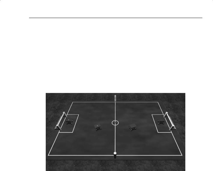
When the simulation engine starts up, it displays the soccer field with four LEGO NXT robots. Each team, red and blue, has a goalkeeper and a field player. The Referee service also displays a window that shows the user interface for controlling the match. The manifest starts the simulation engine with the
SimulatedSoccer.legonxt.fourplayers.state.xml state file. This file contains the soccer scene, including the soccer field, the lights and ground, the goalposts, and the player robots, as shown in Figure 9-10.
Figure 9-10
444
www.it-ebooks.info
Chapter 9: Adventures in Simulation
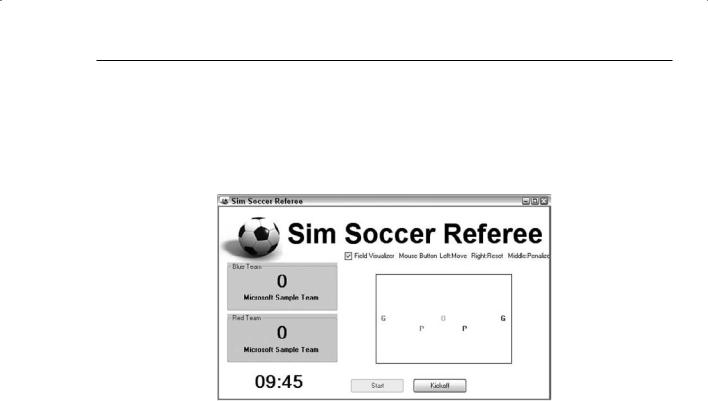
When you click the Start button in the Referee window, the players and ball are reset to their kickoff position and the match begins. While the match is running, a rough ASCII representation of the soccer field displays with a single letter for each player and the ball. You can drag these representations with the left mouse button to move the players or the ball on the field. Right-clicking a player moves it back to its default kickoff position, and middle-clicking a player puts it into a 30-second penalty during which it cannot move. This is shown in Figure 9-11.
Figure 9-11
Each match lasts 10 minutes but the referee does not automatically stop the player action when the time expires. A point is scored for the blue team each time the ball enters the blue goal, and the red team scores when the ball enters the yellow goal. At any time, you can click the Kickoff button to return the players to their default position and orientation. This is useful if one or more of the robots gets stuck. If a single robot tips over, it can be reset by leftor right-clicking it.
Each soccer player has a camera mounted on it so you can see the game from each player’s perspective; you can press the F8 key to switch between cameras or you can select the appropriate camera from the Camera menu.
Each player has a SimulatedDifferentialDrive service associated with it to move it around the field. Each player also has a SimulatedWebcam service associated with it to retrieve images from the onboard camera for processing. The orchestration service, which controls the behavior of the soccer players, is called SimpleSoccerPlayer. This service is designed to work with both the field player and the goalkeeper. In the manifest referenced above, this service controls both teams, so the behavior of both teams is identical.
The soccer player robot entities are identified by the Referee service according to their names. Press F5 while the soccer simulation is running to see the name of each entity. The name of the blue team field player, for example, is blueteam/field/2/simulatedsoccerplayer/robotmotioncontrol. It has a child entity, which is a real-time camera, with the name of blueteam/field/2/simulatedsoccerplayer/robocam.
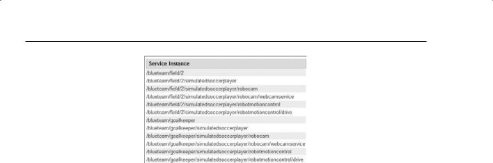
Open the service directory for the DSS node by pointing your browser to http://localhost:50000/ directory while the soccer simulation is running, and you will see something similar to Figure 9-12.
445
www.it-ebooks.info
Part II: Simulations
Figure 9-12
These are the services associated with the blue team players. The /blueteam/field/2 service is the SimpleSoccerPlayer orchestration service that controls the behavior of this player. It implements the simulatedsoccerplayer contract as an alternate contract so that the Referee service can communicate with it. The /blueteam/field/2/simulatedsoccerplayer/robocam service is a SimulatedWebcam service associated with the camera on this player. It implements the webcamservice contract as an alternate contract. The /blueteam/field/2/simulatedsoccerplayer/robotmotioncontrol service is a SimulatedDifferentialDrive service that implements the GenericDifferentialDrive contract as an alternate contract. Notice that the names of the services correspond to the names of the entities they are paired with in the simulation environment.
When the SimpleSoccerPlayer service starts, it sends a message to the Referee service announcing its presence. The Referee service checks the name of the player and finds running services with matching names, passing information about these services back to the player. The player uses the services to control its entity in the simulation environment. The SimpleSoccerPlayer never interacts directly with its entity in the simulator, only with the DifferentialDrive and Webcam services attached to the entity. This makes it possible for the player services to be running on a different node or even a different computer from the simulator simply by changing the manifest.
Changing the Players on the Field
The soccer environment in the Microsoft package is configured to use LEGO NXT robots on the field. These robots are fine but they tend to tip over easily. In this section, you’ll change the environment to use the simulated Corobot entity defined in Chapter 6.
As previously described, everything in the soccer simulation environment is defined in the simulatedsoccer.legonxt.fourplayers.state.xml file. It is easy to remove the LEGO robots from the environment by deleting their XML descriptions from the state file.
A new manifest has been provided in the ProMRDS\config directory: simulatedsoccer.corobot
.fourplayers.manifest.xml. This manifest uses the state file called simulatedsoccer
.corobot.fourplayers.state.xml, which does not contain the LEGO robots. If the simulation environment does not contain four properly named entities, then their corresponding DifferentialDrive services will not appear in the service directory and the referee will be unable to start the match. In this case, the Start button is disabled.
446

www.it-ebooks.info
Chapter 9: Adventures in Simulation
You can add your own player entities to the environment by adding their serialized state to the simulator state file or by creating a service that inserts them into the simulation environment programmatically. You will find the CorobotSoccerPlayers service in the Chapter9 directory, which inserts the entities into the environment using the following code:
corobot.CorobotEntity blueGoalKeeper; corobot.CorobotEntity blueField;
protected override void Start()
{
base.Start();
// create four Corobot Soccer Players blueGoalKeeper = new corobot.CorobotEntity(
“blueteam/goalkeeper/simulatedsoccerplayer/robotmotioncontrol”, new Vector3(0.5f, 0, 0));
RenameCamera(blueGoalKeeper,
“blueteam/goalkeeper/simulatedsoccerplayer/robocam”); blueGoalKeeper.InsertEntity(new TeamIDEntity(new Vector4(0, 0, 1, 1),
blueGoalKeeper.State.Name + “_ID”)); SimulationEngine.GlobalInstancePort.Insert(blueGoalKeeper);
blueField = new corobot.CorobotEntity( “blueteam/field/2/simulatedsoccerplayer/robotmotioncontrol”, new Vector3(2f, 0, 0));
RenameCamera(blueField, “blueteam/field/2/simulatedsoccerplayer/robocam”); blueField.InsertEntity(new TeamIDEntity(new Vector4(0, 0, 1, 1),
blueField.State.Name + “_ID”)); SimulationEngine.GlobalInstancePort.Insert(blueField);
Each player entity is created with the proper name. The camera child entity is renamed to match the soccer environment naming convention. An additional child entity is added consisting of a colored sphere to identify the team affiliation of each robot. This customization makes it much easier to tell which robot is on which team.
The CorobotSoccerPlayers service is started in the manifest along with the Players, DifferentialDrive, and Webcam services and the SimulatedSoccerReferee service. When this service adds the entities to the simulation environment, the simulator notifies the services that have requested notifications. These services then insert themselves into the service directory, and when the Players services announce themselves, the Referee service can find the proper services and the Start button is enabled.
The CorobotSoccerPlayers service does a couple of other tricky things. It subscribes to the simulation engine for a notification when the player entities are inserted into the environment:
// add a handler for the notification from the simulation engine MainPortInterleave.CombineWith(
Arbiter.Interleave(
new TeardownReceiverGroup(), new ExclusiveReceiverGroup
(
|
Arbiter.Receive<InsertSimulationEntity>(false, _notificationTarget, |
|
InsertEntityNotificationHandler), |
|
Arbiter.Receive(true, _timerPort, TimerHandler) |
), |
(continued) |
447

www.it-ebooks.info
Part II: Simulations
(continued)
new ConcurrentReceiverGroup()
)
);
// request a notification when a player is inserted into the sim engine EntitySubscribeRequestType esrt = new EntitySubscribeRequestType(); esrt.Name = blueField.State.Name; SimulationEngine.GlobalInstancePort.Subscribe(esrt, _notificationTarget);
When the service receives this notification, it initializes the main camera view to a top-down view that is more convenient than the default view provided by the Referee service:
//override the viewpoint set up by the referee by waiting until
//the first player is inserted into the simulator and then setting
//the main camera view.
void InsertEntityNotificationHandler(InsertSimulationEntity ins)
{
// Set up initial view
CameraView view = new CameraView(); view.EyePosition = new Vector3(0.02f, 3.66f, 3.42f); view.LookAtPoint = new Vector3(0.02f, 2.87f, 2.81f); SimulationEngine.GlobalInstancePort.Update(view);
}
The CorobotSoccerPlayers service keeps track of the player entities once they have been created and inserted to ensure that they remain upright. It is not uncommon for the robots to push each other over as they jockey for position on the field. Once a robot is on its side, it must be manually reset using the referee user interface.
The CorobotSoccerPlayers service starts a TimerHandler method that is executed periodically. It examines the pose of each of the players. If it detects that a player has been knocked over, it rights it:
Activate(Arbiter.Receive(false, TimeoutPort(10000), _timerPort.Post));
}
Port<DateTime> _timerPort = new Port<DateTime>();
void TimerHandler(DateTime time)
{
AdjustIfNecessary(redGoalKeeper);
AdjustIfNecessary(redField);
AdjustIfNecessary(blueGoalKeeper);
AdjustIfNecessary(blueField);
Activate(Arbiter.Receive(false, TimeoutPort(500), _timerPort.Post));
}
// right a robot that has fallen over
void AdjustIfNecessary(VisualEntity entity)
{
xna.Vector3 rotation = entity.Rotation;
448
www.it-ebooks.info
Chapter 9: Adventures in Simulation
if ((Math.Abs(rotation.X) > 75) || (Math.Abs(rotation.Z) > 75))
{
entity.Rotation = new xna.Vector3(0, 0, 0);
}
}
Although it is not very realistic to have the robots magically right themselves, it does make the soccer matches more interesting to watch. Not everything done in the simulator has to be a reflection of the real world.
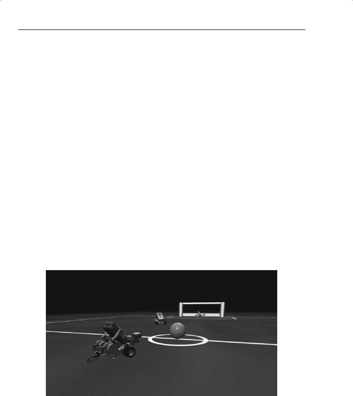
You can run the modified soccer environment using the ProMRDSSoccer.cmd file as follows:
C:\Microsoft Robotics Studio (1.5)>ProMRDSSoccer
You should see something similar to the environment shown in Figure 9-13.
Figure 9-13
Building a Better Soccer Player
The behavior of the SimpleSoccerPlayer shipped with the soccer package is very simple. The robot spins slowly, looking for the soccer ball. When it has located the ball, it drives toward it. When it loses sight of the ball, it repeats this behavior.
Even this very simple behavior can result in some interesting behavior on the field. The robot players do occasionally manage to make a goal, although there is no guarantee that it will be in the proper goal box.
A ProMRDSsimplesoccerplayer service has been provided in the Chapter9 directory, which is essentially the same as the Microsoft SimpleSoccerPlayer service with a few minor modifications to make it work better with the Corobot entity. The most significant change is in the code that creates a port to talk to the DifferentialDrive service. It must append the string “/drive” to the service name so that the port talks to the GenericDrive contract of the SimulatedQuadDifferentialDrive service. Some of the
449

www.it-ebooks.info
Part II: Simulations
drive power factors have also been scaled to better match the gearing of the Corobot model. Other than this, the behavior of SimpleSoccerPlayer has not been changed.
Improved Image Processing
The ProMRDSbettersoccerplayer service in the Chapter9 directory implements several enhancements that improve the soccer player behavior substantially. One of the most significant changes is in the vision processing code. The original soccer player only had the ability to recognize the soccer ball. An improved soccer player must be able to recognize both the yellow and blue goals as well as the ball.
The original image processing code, as well as the new and improved code, uses the HSV color space to identify objects in the image. HSV is an alternate way of representing colors that is different from RGB. The letters stand for the following:
H: Stands for hue and it represents the base color. Its value ranges from 0, which represents red, to 360, which represents violet.
S: Stands for saturation and is a measure of how “washed out” the color is. High values of saturation result in colors that are closer to white, like pastels, whereas low values of saturation yield deep, rich colors.
V: Stands for value and it scales the intensity of the color. Low V values yield colors that are nearly black.
One reason why HSV is a good way to classify colors in an image is because it is possible to ignore the V component of a color to take into account the variations in color intensity due to lighting and shadows. For example, the image processing code in the original SimpleSoccerPlayer service searches for colors in the image that have a very low hue and a reasonably high saturation. This selects pixels in the image that are red regardless of whether they are dark red or bright red.
The new and improved image processing code enables hue and saturation ranges to be specified for each object that needs to be identified. You can find it in the ProMRDSBetterSoccerPlayer project in the
Chapter9 directory in VisionProcessing.cs:
public class ImageSegment
{
public float Saturation; public float SaturationEpsilon; public float Hue;
public float HueEpsilon; public float Area; public float X;
public int XMin; public int XMax; public int XSpan;
}
public static class ImageProcessing
{
///<summary>
///Find objects in the image, using the segment definitions provided
///</summary>
public static void ProcessFrameHandler(
450

www.it-ebooks.info
Chapter 9: Adventures in Simulation
float width, float height,
ImageSegment [] segments, byte[] rgbValues)
{
// initialize the results
foreach (ImageSegment segment in segments)
{
segment.Area = segment.X = 0; segment.XMax = 0;
segment.XMin = (int)(width + 1);
}
// scan the image int offset = 0;
for (int y = 0; y < height; y++)
{
for (int x = 0; x < width; x++)
{
int r, g, b;
b = rgbValues[offset++]; g = rgbValues[offset++]; r = rgbValues[offset++];
Color color = Color.FromArgb(r, g, b);
float hue = color.GetHue();
float saturation = color.GetSaturation();
foreach (ImageSegment segment in segments)
{
if ((Math.Abs(hue - segment.Hue) < segment.HueEpsilon) && (Math.Abs(saturation - segment.Saturation) < segment.SaturationEpsilon))
{
segment.Area++; segment.X += x;
segment.XMax = Math.Max(segment.XMax, x); segment.XMin = Math.Min(segment.XMin, x);
}
}
}
}
foreach (ImageSegment segment in segments)
{
if (segment.Area > 0)
{
segment.X = segment.X / segment.Area; segment.XSpan = segment.XMax - segment.XMin;
}
}
}
}
451

www.it-ebooks.info
Part II: Simulations
The ProcessFrameHandler method steps through each pixel in the image and calculates the hue and saturation values. These values are compared to the ranges specified in each ImageSegment structure that is passed. If it matches a particular segment, then the count for that segment is calculated and the minimum X and maximum X values for the segment are updated. After all of the pixels have been classified, the average X value and the XSpan are calculated for each segment.
The call to ProcessFrameHandler is in the ProcessFrameAndDetermineBehavior method in
BetterSoccerPlayer.cs:
if (_segments[0] == null)
{
_segments[0] = new ImageSegment(); _segments[0].Hue = 0.1f; _segments[0].HueEpsilon = 0.1f; _segments[0].Saturation = 0.75f; _segments[0].SaturationEpsilon = 0.5f; _segments[1] = new ImageSegment(); _segments[1].Hue = 180f; _segments[1].HueEpsilon = 5f; _segments[1].Saturation = 0.75f; _segments[1].SaturationEpsilon = 0.5f; _segments[2] = new ImageSegment(); _segments[2].Hue = 60f; _segments[2].HueEpsilon = 5f; _segments[2].Saturation = 0.75f; _segments[2].SaturationEpsilon = 0.5f;
}
try
{
ImageProcessing.ProcessFrameHandler( _queryFrameRequest.Size.X, _queryFrameRequest.Size.Y, _segments,
_lastFrame);
}
catch (Exception ex)
{
LogError(ex);
}
_segments[0] identifies the soccer ball and selects all pixels that have a hue between 0 and 0.2 and a saturation between 0.25 and 1.0. _segments[1] defines hue and saturation values for the blue goal, and _segments[2] defines hue and saturation values for the yellow goal. These values were determined experimentally by running the soccer simulation and then using the Simulation Editor to select each object and display its hue and saturation.
Select the object you want to measure by holding down the Ctrl key and right-clicking it. Expand the Meshes property and then the Rendering Materials property. Select the desired Rendering Material in the object and click the ellipse that appears to display the MaterialEditor. This dialog shows the HSV and RGB values for the ambient, diffuse, and specular colors of the object (see Figure 9-14).
452