

|
SECTION 2 |
|
|
FLIGHT INSTRUMENTS |
|
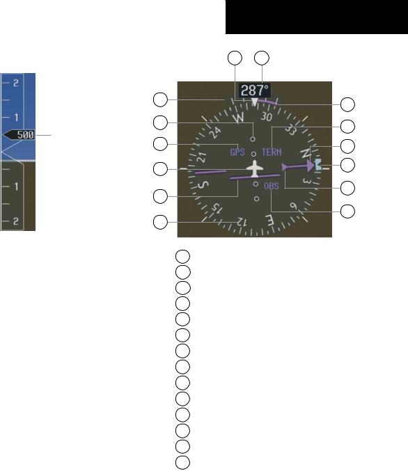
2.6 VERTICAL SPEED INDICATOR |
14 13 |
|
1 |
12 |
|
|
||
2 |
11 |
|
Vertical Speed Pointer |
||
|
||
3 |
10 |
|
4 |
9 |
|
|
||
5 |
8 |
|
|
||
6 |
7 |
|
|
Figure 2-9 Vertical Speed Indicator
The actual vertical speed is displayed inside the point-
er.
2.7HORIZONTAL SITUATION INDICATOR (HSI)
The HSI compass can be displayed as a 360° rose or 140° arc by pressing the PFD softkey, followed by the 360 HSI or the ARC HSI softkey.
1Turn Rate Indicator
2Lateral Deviation Scale
3Navigation Source
4Aircraft Symbol
5Course Deviation Indicator
6Rotating Compass Rose
7OBS Mode
8TO/FROM Indicator
9 Heading Bug
10Course Pointer
11Flight Phase
12Turn Rate and Heading Trend Vector
13Heading
14Lubber Line
Figure 2-10 Horizontal Situation Indicator
Garmin G1000 Cockpit Reference Guide for the Cessna Nav III |
2-5 |
SECTION 2
FLIGHT INSTRUMENTS
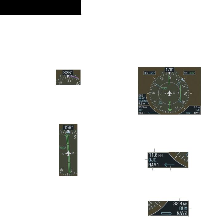
Turn Rate Indicator and Heading Trend Vector
Each tick mark is at 9 (half standard rate tick mark) and 18 (standard rate tick mark) degrees to the left and right of the lubber line. A wide magenta line displays the current turn rate, up to 24 degrees. A magenta arrowhead appears at 25 degrees. This trend vector provides the pilot with a prediction of what the heading will be in 6 seconds at the present turn rate.
Figure 2-11 Turn Rate Indicator and Heading Trend Vector
Course Pointer
The course pointer is a single line arrow (GPS, VOR1 andLOC1)ordoublelinearrow(VOR2andLOC2)which points in the direction of the set course.
Figure 2-12 Course Pointer
Course Deviation Indicator (CDI)
The CDI scale automatically adjusts to the current phase of flight (enroute 5.0 nm, terminal area 1.0 nm, or approach 0.3 nm). Scaling may be selected manually from the MFD System Setup Page. See the MFD section of the pilot’s guide for more details.
Bearing Pointers and Information Windows
Pressing the PFD softkey provides access to the BRG1
and BRG2 softkeys. The BRG1 pointer is a single line pointer. The BRG2 pointer is a double line pointer. Press the BRG1 or BRG2 softkey to cycle through selecting NAV1/2, GPS, or ADF for display using the corresponding pointer.
DME |
Bearing 1 |
Bearing 2 |
|
|
||||
Information |
CDI |
|||||||
Window |
Pointer |
Pointer |
||||||
|
|
|
|
|
|
|
|
|
|
|
|
|
|
|
|
|
|
|
|
|
|
|
|
|
|
|
|
|
|
|
Bearing 1 |
Bearing 2 |
||
Information |
Information |
||
Window |
Window |
||
Figure 2-13 HSI with Bearing Information
Distance to
Bearing Source
Waypoint
Identifier
Bearing Pointer
Source Icon
Figure 2-14 BRG1 Information Window
Distance to
Bearing Source
Waypoint
Identifier
|
|
|
|
Pointer |
Bearing |
||
Icon |
Source |
||
Figure 2-15 BRG2 Information Window
2-6 |
Garmin G1000 Cockpit Reference Guide for the Cessna Nav III |
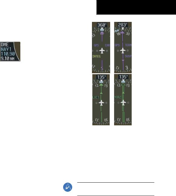
DME (optional)
To display the DME Information Window, press the PFD softkey followed by the DME softkey.
Figure 2-16 DME Information Window
Navigation Source
To change between CDI navigation sources:
1.Press the CDI softkey to change from GPS to VOR1/LOC1.
2.Press the CDI softkey again to change from VOR1/LOC1 to VOR2/LOC2.
3.Press the CDI softkey a third time to return to GPS.
When using GPS as the navigation source, the following may appear:
•INTEG – RAIM is not available
•WARN – GPS detects a position error
•SUSP – Displayed when in OBS Mode indicating GPS navigation is suspended.
SECTION 2
FLIGHT INSTRUMENTS
Figure 2-17 GPS INTEG, GPS SUSP, LOC1 and VOR2
To enable/disable OBS mode while navigating with GPS:
1.Press the OBS softkey to select OBS Mode.
2.Turn the CRS knob to select the desired course TO/FROM the waypoint.
3.Pressthe OBS softkeyagaintoreturntonormal operation.
NOTE: The OBS softkey is only displayed when navigating an active leg.
Garmin G1000 Cockpit Reference Guide for the Cessna Nav III |
2-7 |

SECTION 2
FLIGHT INSTRUMENTS
.
This page intentionally left blank.
2-8 |
Garmin G1000 Cockpit Reference Guide for the Cessna Nav III |