

SECTION 12 – ANNUNCIATIONS
& ALERTS
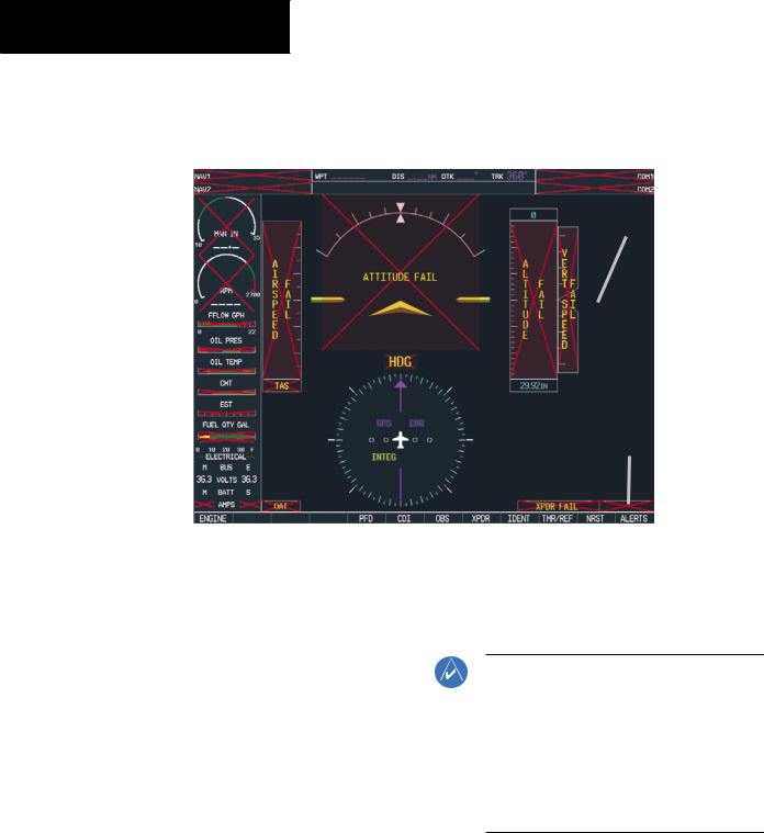
A red ‘X’ may be the result of an LRU or an LRU func- |
|
|
|
|
|
|||||||||||||
tion failure. The Figure 12-5 illustrates all possible flags |
|
|
|
|
|
|||||||||||||
and the responsible LRUs. |
|
|
|
|
|
|||||||||||||
GIA 63 Integrated |
|
|
|
|
|
|
|
|
|
|
|
GIA 63 Integrated |
||||||
|
|
|
|
|
|
|
|
|||||||||||
Avionics Units |
|
|
|
|
Avionics Units |
|||||||||||||
|
|
|
|
|
|
|
|
|
|
|
|
|
|
|
|
|
|
GDC 74A Air Data |
|
|
|
|
|
|
|
|
|
|
|
|
|
|
|
|
|
|
|
|
|
|
|
|
|
|
|
|
|
|
|
|
|
|
|
|
|
|
|
|
|
|
|
|
|
|
|
|
|
|
|
|
|
|
|
|
Computer |
|
|
|
|
|
|
|
|
|
|
|
|
|
|
|
|
|
|
GRS 77 AHRS |
|
|
|
|
|
|
|
|
|
|
|
|
|
|
|
|
|
|
|
|
|
|
|
|
|
|
|
|
|
|
|
|
|
|
|
|
|
|
|
|
|
|
|
|
|
|
|
|
|
|
|
|
|
|
|
|
|
GEA 71 Engine |
|
|
|
|
|
|
|
|
|
|
|
OR |
||||||
|
|
|
|
|
|
|
|
|
|
|
|
|
|
|
|
|||
Airframe Unit |
|
|
|
|
|
|
|
|
|
|
GMU 44 |
|||||||
OR |
|
|
|
|
|
|
|
|
|
|
Magnetometer |
|||||||
GIA 63 Integrated |
|
|
|
|
|
|
|
|
|
|
|
|||||||
Avionics Unit |
|
|
|
|
|
|
|
|
|
|
|
|
GIA 63 Integrated |
|||||
|
|
|
|
|
|
|
|
|
|
|
|
|
|
|
|
|
|
|
|
|
|
|
|
|
|
|
|
|
|
|
|
|
|
|
|
|
|
|
|
|
|
|
|
|
|
|
|
|
|
|
|
|
|
|
|
Avionics Units |
|
|
|
|
|
|
|
|
|
|
|
|
|
|
|
|
|
|
GTX 33 Transponder |
|
|
|
|
|
|
|
|
|
|
|
|
|
|
|
|
|
|
|
|
|
|
|
GDC 74A Air Data |
|
|
|
|
|
|
|
|
|
|||||
|
|
|
|
|
|
|
|
|
|
|
|
|
||||||
|
|
|
|
|
|
|
|
|
|
|
|
|
OR |
|||||
|
|
|
|
Computer |
|
|
|
|
||||||||||
|
|
|
|
|
|
|
|
GIA 63 Integrated |
||||||||||
|
|
|
|
|
|
|
|
Figure 12-5 G1000 System Failure Annunciations |
|
|
|
|
||||||
|
|
|
|
|
|
|
|
|
|
|
|
Avionics Units |
||||||
12.6G1000 SYSTEM MESSAGE ADVISORIES
This section describes various G1000 system message advisories. CertainmessagesareissuedduetoanLRUoran LRU function failure. Such messages are normally accompanied by a corresponding red ‘X’ annunciation as shown previously in the G1000 System Annunciation section.
NOTE: This section provides information regarding G1000 message advisories that may be displayed by the system. Knowledge of the aircraft, systems, flight conditions, and other existing operational priorities must be considered when responding to a message. Always use sound pilot judgment. The Cessna aircraft Pilot’s Operating Handbook (POH) takes precedence over any conflicting guidance found in this section.
12-8 |
Garmin G1000 Cockpit Reference Guide for the Cessna Nav III |

|
|
SECTION 12 – ANNUNCIATIONS |
|
|
|
& ALERTS |
|
MFD & PFD Message Advisories |
|
|
|
|
|
|
|
|
|
|
|
Message |
Comments |
|
|
DATA LOST – Pilot stored data was |
The pilot profile data was lost. System reverts to default pilot profile and settings. |
|
|
lost. Recheck settings. |
The pilot may reconfigure the MFD & PFD with preferred settings, if desired. |
|
|
XTALK ERROR –A flight display |
The MFD and PFD are not communicating with each other. The G1000 system should |
|
|
crosstalk error has occurred. |
be serviced. |
|
|
PFD1 SERVICE – PFD1 needs service. |
|
|
|
Return unit for repair. |
The PFD and/or MFD self-test has detected a problem. The G1000 system should be |
|
|
MFD1 SERVICE – MFD1 needs |
serviced. |
|
|
service. Return unit for repair. |
|
|
|
PFD1 CONFIG – PFD1 configuration |
|
|
|
error. Config service req’d. |
The PFD and/or MFD configuration settings do not match backup configuration |
|
|
MFD1 CONFIG – MFD1 configuration |
memory. The G1000 system should be serviced. |
|
|
error. Config service req’d. |
|
|
|
SW MISMATCH – GDU software |
The MFD and PFD have different software versions installed. The G1000 system |
|
|
mismatch. Xtalk is off. |
should be serviced. |
|
|
MANIFEST – PFD1 software mismatch. |
|
|
|
Communication halted. |
The PFD and/or MFD has incorrect software installed. The G1000 system should be |
|
|
MANIFEST – MFD1 software |
serviced. |
|
|
mismatch. Communication halted. |
|
|
|
PFD1 COOLING – PFD1 has poor |
|
|
|
cooling. Reducing power usage. |
The PFD and/or MFD is overheating and is reducing power consumption by dimming |
|
|
MFD1 COOLING – MFD1 has poor |
the display. If problem persists, the G1000 system should be serviced. |
|
|
cooling. Reducing power usage. |
|
|
|
PFD1 “KEY” KEYSTK – Key is stuck. |
A key is stuck on the PFD and/or MFD bezel. Attempt to free the stuck key by press- |
|
|
MFD1 “KEY” KEYSTK – Key is stuck. |
ing it several times. The G1000 system should be serviced if the problem persists. |
|
|
CNFG MODULE – PFD1 configuration |
The PFD configuration module backup memory has failed. The G1000 system should |
|
|
module is inoperative. |
be serviced. |
|
|
Garmin G1000 Cockpit Reference Guide for the Cessna Nav III |
12-9 |

SECTION 12 – ANNUNCIATIONS
& ALERTS
Database Message Advisories
Alerts Window Message |
Comments |
|
MFD1 DB ERR – MFD1 aviation |
|
|
database error exists. |
The MFD and/or PFD detected a failure in the aviation database. Attempt to reload |
|
PFD1 DB ERR – PFD1 aviation |
the aviation database. If problem persists, the G1000 system should be serviced. |
|
database error exists. |
|
|
MFD1 DB ERR – MFD1 basemap |
|
|
database error exists. |
The MFD and/or PFD detected a failure in the basemap database. |
|
PFD1 DB ERR – PFD1 basemap |
||
|
||
database error exists. |
|
|
MFD1 DB ERR – MFD1 terrain |
The MFD and/or PFD detected a failure in the terrain database. Ensure that the ter- |
|
database error exists. |
||
rain card is properly inserted in display. Replace terrain card. If problem persists,The |
||
PFD1 DB ERR – PFD1 terrain database |
||
G1000 system should be serviced. |
||
error exists. |
|
|
DB MISMATCH –Aviation database |
The PFD and MFD have different aviation database versions installed. Crossfill is off. |
|
version mismatch. Xtalk is off. |
Install correct aviation database version in both displays. |
|
DB MISMATCH –Aviation database |
The PFD and MFD have different aviation database types installed (Americas, Euro- |
|
type mismatch. Xtalk is off. |
pean, etc.). Crossfill is off. Install correct aviation database type in both displays. |
|
DB MISMATCH – Basemap database |
The PFD and MFD have different basemap database versions installed. Crossfill is |
|
version mismatch. Xtalk is off. |
off. Install correct basemap database version in both displays. |
|
DB MISMATCH –Terrain database |
The PFD and MFD have different terrain database versions installed. Crossfill is off. |
|
version mismatch. Xtalk is off. |
Install correct terrain database version in both displays. |
|
DB MISMATCH –Terrain database |
The PFD and MFD have different terrain database types installed. Crossfill is off. |
|
type mismatch. Xtalk is off. |
Install correct terrain database type in both displays. |
|
DB MISMATCH – Obstacle database |
The PFD and MFD have different obstacle database versions installed. Crossfill is off. |
|
version mismatch. Xtalk is off |
Install correct obstacle database version in both displays. |
|
DB MISMATCH –AirportTerrain |
The PFD and MFD have different airport terrrain databases installed. Crossfill is off. |
|
database mismatch. Xtalk is off |
Install correct airport terrain database in both displays. |
12-10 |
Garmin G1000 Cockpit Reference Guide for the Cessna Nav III |

|
|
SECTION 12 – ANNUNCIATIONS |
||
|
|
& ALERTS |
||
GMA 1347 Message Advisories |
|
|
|
|
|
|
|
|
|
|
|
|
|
|
Alerts Window Message |
Comments |
|
||
GMA1 FAIL – GMA1 is inoperative. |
The audio panel self-test has detected a failure. The audio panel is unavailable. The |
|
||
|
G1000 system should be serviced. |
|
||
GMA1 CONFIG – GMA1 configuration |
The audio panel configuration settings do not match backup configuration memory. |
|
||
error. Config service req’d. |
The G1000 system should be serviced. |
|
||
MANIFEST – GMA1 software |
The audio panel has incorrect software installed. The G1000 system should be |
|
||
mismatch. Communication halted. |
serviced. |
|
||
GMA1 SERVICE – GMA1 needs |
The audio panel self-test has detected a problem in the unit. Certain audio functions |
|
||
service. Return unit for repair. |
may still be available, and the audio panel may still be usable. The G1000 system |
|
||
|
should be serviced when possible. |
|
||
BACKUP PATH –Audio panel 1 using |
The #1 audio panel is using a backup communication path. The G1000 system |
|
||
backup data path. |
should be serviced when possible. |
|
||
GIA 63 Message Advisories |
|
|
|
|
|
|
|
||
Alerts Window Message |
Comments |
|
|
|
GIA1 CONFIG – GIA1 configuration |
|
|
|
|
error. Config service req’d. |
The GIA1 and/or GIA2 configuration settings do not match backup configuration |
|
||
GIA2 CONFIG – GIA2 configuration |
memory. The G1000 system should be serviced. |
|
|
|
error. Config service req’d. |
|
|
|
|
GIA1 COOLING – GIA1 temperature |
|
|
|
|
too low. |
The GIA1 and/or GIA2 temperature is too low to operate correctly. Allow units to |
|
||
GIA2 COOLING – GIA2 temperature |
warm up to operating temperature. |
|
|
|
too low. |
|
|
|
|
GIA1 COOLING – GIA1 over |
|
|
|
|
temperature. |
The GIA1 and/or GIA2 temperature is too high. If problem persists, the G1000 |
|
||
GIA2 COOLING – GIA2 over |
system should be serviced. |
|
|
|
temperature. |
|
|
|
|
GIA1 SERVICE – GIA1 needs service. |
|
|
|
|
Return the unit for repair. |
The GIA1 and/or GIA2 self-test has detected a problem in the unit. The G1000 |
|
||
GIA2 SERVICE – GIA2 needs service. |
system should be serviced. |
|
|
|
Return the unit for repair. |
|
|
|
|
Garmin G1000 Cockpit Reference Guide for the Cessna Nav III |
12-11 |

SECTION 12 – ANNUNCIATIONS
& ALERTS
GIA 63 Message Advisories (Cont.)
Alerts Window Message |
Comments |
|
MANIFEST – GIA1 software mismatch. |
|
|
Communication halted. |
The GIA1 and/or GIA 2 has incorrect software installed. The G1000 system should |
|
MANIFEST – GIA2 software mismatch. |
be serviced. |
|
Communication halted. |
|
|
COM1 TEMP – COM1 over temp. |
The system has detected an over temperature condition in COM1 and/or COM2. The |
|
Reducing transmitter power. |
||
transmitter will operate at reduced power. If the problem persists, the G1000 system |
||
COM2 TEMP – COM2 over temp. |
||
should be serviced. |
||
Reducing transmitter power. |
||
|
||
COM1 SERVICE – COM1 needs |
|
|
service. Return unit for repair. |
The system has detected a failure in COM1 and/or COM2. COM1 and/or COM2 may |
|
COM2 SERVICE – COM2 needs |
still be usable. The G1000 system should be serviced when possible. |
|
service. Return unit for repair. |
|
|
COM1 PTT – COM1 push-to-talk key |
The COM1 and/or COM2 external push-to-talk switch is stuck in the enable (or |
|
is stuck. |
||
“pressed”) position. Press the PTT switch again to cycle its operation. |
||
COM2 PTT – COM2 push-to-talk key |
||
If the problem persists, the G1000 system should be serviced. |
||
is stuck. |
||
|
||
|
|
|
COM1 RMT XFR – COM1 remote |
The COM1 and/or COM2 transfer switch is stuck in the enabled (or “pressed”) posi- |
|
transfer key is stuck. |
||
tion. Press the transfer switch again to cycle its operation. If the problem persists, |
||
|
||
COM2 RMT XFR – COM2 remote |
||
the G1000 system should be serviced. |
||
transfer key is stuck. |
||
|
||
RAIM UNAVAIL – RAIM is not |
GPS satellite coverage is insufficient to perform ReceiverAutonomous Integrity |
|
available from FAF to MAP waypoints. |
Monitoring (RAIM) from the FAF to the MAP waypoints. |
|
RAIM UNAVAIL – RAIM is not |
GPS satellite coverage is insufficient to perform ReceiverAutonomous Integrity |
|
available. |
Monitoring (RAIM) for the current phase of flight. |
|
POSN ERROR – RAIM has determined |
When a RAIM position error is detected, GPS is flagged and the system no longer |
|
GPS position is in error. |
provides GPS-based guidance. |
|
DGRD GPS ACC – GPS position |
GPS position accuracy has been degraded and RAIM is not available. |
|
accuracy degraded & RAIM unavailable. |
||
|
|
|
GPS1 FAIL – GPS1 is inoperative. |
|
|
|
A failure has been detected in the GPS1 and/or GPS2 receiver. The receiver is |
|
GPS2 FAIL – GPS2 is inoperative. |
unavailable. The G1000 system should be serviced. |
|
|
|
12-12 |
Garmin G1000 Cockpit Reference Guide for the Cessna Nav III |