


 t
t
318 |
Spread Spectrum and CDMA |
|
|
(MC-DS-CDMA). The source ‘fast’ bit stream of rate R ¼ 1/Tb is demultiplexed (split) into Mc parallel ‘slow’ bit streams of rate R/Mc (or bit duration T 0b ¼ McTb) each. The ith slow bit stream is transmitted on its specific subcarrier of frequency fi, i ¼ 1, 2, . . . , Mc using DS spreading and some data modulation mode (BPSK, QPSK or other mode). With spreading chip duration D0 and subcarrier data symbol duration T 0p the bandwidth and spreading factor of one subcarrier signal are found as W0 1/D0 and N0 ¼ T 0p/D0 W 0T 0p, respectively. Spacing F of the subcarrier frequencies should exclude spectra overlapping, i.e. meet the restriction F ¼ W0 þ Fg, where Fg is a guard interval allowing for out-of-band spectra sidelobes. Therefore the total bandwidth occupied by the system:
W ¼ ðMc 1ÞF þ W0 ¼ McW0 þ ðMc 1ÞFg: |
ð10:26Þ |
The receiver of MC-DS-CDMA consists of Mc parallel identical receivers, each tuned on its own subcarrier and processing it independently of the others. Demodulated slow bit streams from their outputs are then multiplexed to restore the transmitted source fast bit stream.
Comparison of this system with DS CDMA of the same total bandwidth W and data rate R shows that due to the necessity for guard intervals MC-DS-CDMA yields to DS-CDMA in spreading factor. If both systems use the same modulation mode then symbol duration Tp for DS CDMA should be Mc times shorter than the MC-DS-CDMA symbol duration T 0p, but chip duration in DS CDMA may be taken as D 1/W providing the spreading factor N ¼ Tp/D WT 0p/Mc. In accordance with (10.26) the ratio of this entity to the spreading factor of MC-DS-CDMA:
N |
|
1 |
|
Mc 1 |
Fg |
|
1 |
ðMc 1ÞFg |
|
10:27 |
|
|
N0 |
¼ |
þ |
Mc W0 |
¼ |
þ W ðMc 1ÞFg |
ð |
Þ |
|||||
|
|
|
||||||||||
may remarkably exceed one. Since the spreading factor is the most important parameter of CDMA, determining user capacity, jamming immunity etc., MC-DS-CDMA proves to be not the best potential option for utilization of the available spectral resource. Sometimes, however, other factors may prevail, as takes place in the specification of cdma2000, which recommends MC-DS-CDMA for arranging a downlink on the grounds of backward compatibility with cdmaOne. In this case the single-carrier format of cdmaOne (slightly modified) is just replicated on three appropriately spaced carriers.
10.2.2 Conventional MC transmission and OFDM
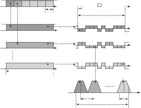
Let us digress for a while from spread spectrum and CDMA to get a better understanding of the reasons underlying the considerable interest in the MC technique in modern wireless telecommunication. Suppose one wants to transmit a source bit stream using some conventional (non-spread-spectrum) modulation mode (BPSK, QPSK etc.). With M-ary modulation and necessary data transmission rate R, the duration of the data symbol pulse is Tp ¼ ( log2 M)/R. Suppose that the channel coherence bandwidth Bc (see Section 3.6) is significantly narrower than the bandwidth of data symbols (Bc W 1/Tp ¼ R/ log2 M), or, putting it differently, the delay spread ds exceeds symbol duration remarkably. Then under the ‘direct’ transmission (see Figure 10.3a),

Spread spectrum systems development |
|
|
|
319 |
Source (fast) bitstream |
|
Single carrier power spectrum |
|
|
|
|
|
|
|
(a) |
|
|
|
|
|
t |
f0 |
|
f |
Tb |
|
|
|
|
|
|
|
|
|
|
|
R |
|
|
1st slow bit stream |
|
W ≈ 1/Tp = |
|
|
|
|
log2 M |
|
|
|
t |
Subchannel power |
|
|
|
spectra |
|
|
|
|
|
|
|
|
2nd slow bit stream |
|
|
|
|
(b) |
|
|
|
|
|
t |
|
|
|
Mcth slow bit stream |
|
f1 f2 |
fMc |
f |
|
|
|
W ′ ≈ 1 |
|
|
|
F = W ′ |
|
|
|
t |
|
|
Tp′ |
Tb′ = McTb |
|
|
|
|
|
Overall MC spectrum |
|
||
|
|
|
||
|
|
|
|
f |
|
|
R |
|
|
|
|
W = McW ′ = |
|
|
|
|
log2 M |
|
|
Figure 10.3 Single-carrier (a) and MC (b) data transmission
a deep ISI (see Section 3.5.4) will be present, distorting the data symbols following the current one. To counter it the receiver will have to involve a rather complex equalizer with a long memory, typically realized as an adaptive FIR filter, i.e. tapped delay-line with adjustable tap weights.
MC transmission offers an alternative solution (Figure 10.3b) avoiding the need for complex equalizing. Let us again demultiplex the ‘fast’ source bit stream of rate R to Mc W/Bc parallel ‘slow’ bit streams having rate R/Mc each. Certainly, the overall rate provided by all slow bit streams is equal to the original one, i.e. R. Now let us take Mc subcarriers f1, f2, . . . , fMc spaced uniformly with interval F ¼ W0 ¼ W/Mc and use each of them to transmit one of Mc slow bit streams in the same modulation mode as before. Every individual subcarrier forms a separate subchannel operating regardless of the others and transmitting a slow bit stream by longer pulses (symbols) of duration Tp0 ¼ McTp, i.e. occupying Mc times narrower bandwidth W0 ¼ W/Mc than before. This means that within a subchannel the fading is no longer frequency-selective, since W0 ¼ W/Mc Bc. For a flat fading the delay spread does not go far beyond a single pulse, and ISI is less dramatic than it was initially and may be countered by comparatively simple equalizers. The total bandwidth occupied by the MC system is around W Mc/T 0p ¼ 1/Tp ¼ R/ log2 M, i.e. equalling that of the single-carrier transmission. In fact, spectral efficiency of the MC system appears to be even better, since the shape of its real spectrum is closer to a rectangle.

Spread spectrum systems development |
321 |
|
|
(10.28). This latter (after introducing a prefix; see below) is up-converted and transmitted on the desired central frequency f0.
At the receiving end there is also no need to use Mc parallel receivers each tuned to its individual subcarrier, since one may extract fbig from (10.29) by the direct discrete Fourier transform (DDFT):
l 0 |
S_l exp j2 ðMi c |
1Þl |
¼ Mcbi; i ¼ 1; 2; . . . ; Mc |
ð10:30Þ |
||
Mc 1 |
|
|
|
|
|
|
X |
|
|
|
|
|
|
¼
This shows that a DDFT unit is an appropriate device to split a received OFDM symbol into Mc subchannel effects necessary to retrieve transmitted data. Still, at the real channel output the receiver does not have at its disposal a ‘pure’ OFDM symbol. Instead it observes a complex envelope Y_ (t), containing an OFDM symbol distorted by noise and ISI. As follows from its principle, the MC technique, increasing symbol duration limits the depth of ISI propagation to the symbol following the current one. To exclude this residual ISI, too, one may insert a guard interval of duration Tg ds between adjacent MC symbols. This interval should not compulsorily be empty. Moreover, filling it with a cyclic prefix of the OFDM symbol remarkably facilitates neutralization of the channel multipath effects. Appending a cyclic prefix serves to convert a convolution of the transmitted signal with the channel pulse response into the cyclic one, corresponding to the product of DFT images. Denote ¼ b ds/Tsc an integer number of sampling intervals in maximal channel delay and append v last samples of (10.29) as a prefix to the transmitted OFDM symbol. The receiver will drop
_ |
. . . , Mc 1, so that multipath replicas of the |
the first samples of Sl, l ¼ , þ 1, |
previous OFDM symbol will not affect Mc samples left. The delayed replicas of the current symbol itself will be influential, however, on the latter samples due to the
channel |
multipath propagation. |
|
If |
the |
channel |
pulse |
response |
samples are |
||||||||||
_ |
_ |
_ |
|
|
|
|
|
|
|
_ |
|
|
|
|
|
|
|
|
H0 |
, H1, . . . , H , then each observation sample Yl, l ¼ 0, 1, . . . , Mc 1 (noise neglected) |
|||||||||||||||||
is found as the convolution: |
X |
|
|
|
|
|
|
|
|
|
|
|
|
|
|
|||
|
|
_ |
_ |
|
|
_ |
|
|
|
|
|
|
|
|
|
ð10:31Þ |
||
|
|
Yl ¼ |
|
Sl mHm; l ¼ 0; 1; . . . ; Mc 1 |
|
|||||||||||||
|
|
|
m¼0 |
|
|
|
|
|
|
|
|
|
|
|
|
|
|
|
Due to the cyclic prefix the sequence |
_ |
¼ 0, 1, . . . , Mc 1 is a cyclic shift of the |
||||||||||||||||
Sl m, l |
||||||||||||||||||
sequence |
_ |
|
. . . , |
|
, therefore (10.31) is a cyclic convolution, and its |
|||||||||||||
Sl for any m ¼ 0, 1, |
|
|||||||||||||||||
|
|
|
|
|
|
|
|
~ |
~ |
|
|
|
|
|
_ |
_ |
||
DFT spectrum is a product of DFTs |
_ |
|
_ |
of sequences |
||||||||||||||
Si and Hi |
Sl and Hl. DFT of the |
|||||||||||||||||
former is just a scaled sequence of modulation symbols fbig (see (10.30)), while |
||||||||||||||||||
|
|
H_ i |
¼ l |
|
0 |
H_ l exp |
|
|
ðMc |
1 |
Þ |
|
|
|
||||
|
|
~ |
|
X |
|
|
|
j2 i |
|
l |
|
|
||||||
|
|
|
|
|
|
|
|
|
|
|
|
|
|
|
|
|
|
|
¼
is the channel transfer function at the frequencies fi ¼ f1, f2, . . . , fMc , so that:
~ |
~ |
|
_ |
_ |
ð10:32Þ |
Yi ¼ McbiHi; i ¼ 1; 2; . . . ; Mc |
||
This result shows that to remove the channel influence on the OFDM signal, i.e. perform equalizing, it is enough to simply divide each sample at the output of the receiver DDFT