

- •Contents
- •Preface
- •1 Spread spectrum signals and systems
- •1.1 Basic definition
- •1.2 Historical sketch
- •2 Classical reception problems and signal design
- •2.1 Gaussian channel, general reception problem and optimal decision rules
- •2.2 Binary data transmission (deterministic signals)
- •2.3 M-ary data transmission: deterministic signals
- •2.4 Complex envelope of a bandpass signal
- •2.5 M-ary data transmission: noncoherent signals
- •2.6 Trade-off between orthogonal-coding gain and bandwidth
- •2.7 Examples of orthogonal signal sets
- •2.7.1 Time-shift coding
- •2.7.2 Frequency-shift coding
- •2.7.3 Spread spectrum orthogonal coding
- •2.8 Signal parameter estimation
- •2.8.1 Problem statement and estimation rule
- •2.8.2 Estimation accuracy
- •2.9 Amplitude estimation
- •2.10 Phase estimation
- •2.11 Autocorrelation function and matched filter response
- •2.12 Estimation of the bandpass signal time delay
- •2.12.1 Estimation algorithm
- •2.12.2 Estimation accuracy
- •2.13 Estimation of carrier frequency
- •2.14 Simultaneous estimation of time delay and frequency
- •2.15 Signal resolution
- •2.16 Summary
- •Problems
- •Matlab-based problems
- •3 Merits of spread spectrum
- •3.1 Jamming immunity
- •3.1.1 Narrowband jammer
- •3.1.2 Barrage jammer
- •3.2 Low probability of detection
- •3.3 Signal structure secrecy
- •3.4 Electromagnetic compatibility
- •3.5 Propagation effects in wireless systems
- •3.5.1 Free-space propagation
- •3.5.2 Shadowing
- •3.5.3 Multipath fading
- •3.5.4 Performance analysis
- •3.6 Diversity
- •3.6.1 Combining modes
- •3.6.2 Arranging diversity branches
- •3.7 Multipath diversity and RAKE receiver
- •Problems
- •Matlab-based problems
- •4 Multiuser environment: code division multiple access
- •4.1 Multiuser systems and the multiple access problem
- •4.2 Frequency division multiple access
- •4.3 Time division multiple access
- •4.4 Synchronous code division multiple access
- •4.5 Asynchronous CDMA
- •4.6 Asynchronous CDMA in the cellular networks
- •4.6.1 The resource reuse problem and cellular systems
- •4.6.2 Number of users per cell in asynchronous CDMA
- •Problems
- •Matlab-based problems
- •5 Discrete spread spectrum signals
- •5.1 Spread spectrum modulation
- •5.2 General model and categorization of discrete signals
- •5.3 Correlation functions of APSK signals
- •5.4 Calculating correlation functions of code sequences
- •5.5 Correlation functions of FSK signals
- •5.6 Processing gain of discrete signals
- •Problems
- •Matlab-based problems
- •6 Spread spectrum signals for time measurement, synchronization and time-resolution
- •6.1 Demands on ACF: revisited
- •6.2 Signals with continuous frequency modulation
- •6.3 Criterion of good aperiodic ACF of APSK signals
- •6.4 Optimization of aperiodic PSK signals
- •6.5 Perfect periodic ACF: minimax binary sequences
- •6.6 Initial knowledge on finite fields and linear sequences
- •6.6.1 Definition of a finite field
- •6.6.2 Linear sequences over finite fields
- •6.6.3 m-sequences
- •6.7 Periodic ACF of m-sequences
- •6.8 More about finite fields
- •6.9 Legendre sequences
- •6.10 Binary codes with good aperiodic ACF: revisited
- •6.11 Sequences with perfect periodic ACF
- •6.11.1 Binary non-antipodal sequences
- •6.11.2 Polyphase codes
- •6.11.3 Ternary sequences
- •6.12 Suppression of sidelobes along the delay axis
- •6.12.1 Sidelobe suppression filter
- •6.12.2 SNR loss calculation
- •6.13 FSK signals with optimal aperiodic ACF
- •Problems
- •Matlab-based problems
- •7 Spread spectrum signature ensembles for CDMA applications
- •7.1 Data transmission via spread spectrum
- •7.1.1 Direct sequence spreading: BPSK data modulation and binary signatures
- •7.1.2 DS spreading: general case
- •7.1.3 Frequency hopping spreading
- •7.2 Designing signature ensembles for synchronous DS CDMA
- •7.2.1 Problem formulation
- •7.2.2 Optimizing signature sets in minimum distance
- •7.2.3 Welch-bound sequences
- •7.3 Approaches to designing signature ensembles for asynchronous DS CDMA
- •7.4 Time-offset signatures for asynchronous CDMA
- •7.5 Examples of minimax signature ensembles
- •7.5.1 Frequency-offset binary m-sequences
- •7.5.2 Gold sets
- •7.5.3 Kasami sets and their extensions
- •7.5.4 Kamaletdinov ensembles
- •Problems
- •Matlab-based problems
- •8 DS spread spectrum signal acquisition and tracking
- •8.1 Acquisition and tracking procedures
- •8.2 Serial search
- •8.2.1 Algorithm model
- •8.2.2 Probability of correct acquisition and average number of steps
- •8.2.3 Minimizing average acquisition time
- •8.3 Acquisition acceleration techniques
- •8.3.1 Problem statement
- •8.3.2 Sequential cell examining
- •8.3.3 Serial-parallel search
- •8.3.4 Rapid acquisition sequences
- •8.4 Code tracking
- •8.4.1 Delay estimation by tracking
- •8.4.2 Early–late DLL discriminators
- •8.4.3 DLL noise performance
- •Problems
- •Matlab-based problems
- •9 Channel coding in spread spectrum systems
- •9.1 Preliminary notes and terminology
- •9.2 Error-detecting block codes
- •9.2.1 Binary block codes and detection capability
- •9.2.2 Linear codes and their polynomial representation
- •9.2.3 Syndrome calculation and error detection
- •9.2.4 Choice of generator polynomials for CRC
- •9.3 Convolutional codes
- •9.3.1 Convolutional encoder
- •9.3.2 Trellis diagram, free distance and asymptotic coding gain
- •9.3.3 The Viterbi decoding algorithm
- •9.3.4 Applications
- •9.4 Turbo codes
- •9.4.1 Turbo encoders
- •9.4.2 Iterative decoding
- •9.4.3 Performance
- •9.4.4 Applications
- •9.5 Channel interleaving
- •Problems
- •Matlab-based problems
- •10 Some advancements in spread spectrum systems development
- •10.1 Multiuser reception and suppressing MAI
- •10.1.1 Optimal (ML) multiuser rule for synchronous CDMA
- •10.1.2 Decorrelating algorithm
- •10.1.3 Minimum mean-square error detection
- •10.1.4 Blind MMSE detector
- •10.1.5 Interference cancellation
- •10.1.6 Asynchronous multiuser detectors
- •10.2 Multicarrier modulation and OFDM
- •10.2.1 Multicarrier DS CDMA
- •10.2.2 Conventional MC transmission and OFDM
- •10.2.3 Multicarrier CDMA
- •10.2.4 Applications
- •10.3 Transmit diversity and space–time coding in CDMA systems
- •10.3.1 Transmit diversity and the space–time coding problem
- •10.3.2 Efficiency of transmit diversity
- •10.3.3 Time-switched space–time code
- •10.3.4 Alamouti space–time code
- •10.3.5 Transmit diversity in spread spectrum applications
- •Problems
- •Matlab-based problems
- •11 Examples of operational wireless spread spectrum systems
- •11.1 Preliminary remarks
- •11.2 Global positioning system
- •11.2.1 General system principles and architecture
- •11.2.2 GPS ranging signals
- •11.2.3 Signal processing
- •11.2.4 Accuracy
- •11.2.5 GLONASS and GNSS
- •11.2.6 Applications
- •11.3 Air interfaces cdmaOne (IS-95) and cdma2000
- •11.3.1 Introductory remarks
- •11.3.2 Spreading codes of IS-95
- •11.3.3 Forward link channels of IS-95
- •11.3.3.1 Pilot channel
- •11.3.3.2 Synchronization channel
- •11.3.3.3 Paging channels
- •11.3.3.4 Traffic channels
- •11.3.3.5 Forward link modulation
- •11.3.3.6 MS processing of forward link signal
- •11.3.4 Reverse link of IS-95
- •11.3.4.1 Reverse link traffic channel
- •11.3.4.2 Access channel
- •11.3.4.3 Reverse link modulation
- •11.3.5 Evolution of air interface cdmaOne to cdma2000
- •11.4 Air interface UMTS
- •11.4.1 Preliminaries
- •11.4.2 Types of UMTS channels
- •11.4.3 Dedicated physical uplink channels
- •11.4.4 Common physical uplink channels
- •11.4.5 Uplink channelization codes
- •11.4.6 Uplink scrambling
- •11.4.7 Mapping downlink transport channels to physical channels
- •11.4.8 Downlink physical channels format
- •11.4.9 Downlink channelization codes
- •11.4.10 Downlink scrambling codes
- •11.4.11 Synchronization channel
- •11.4.11.1 General structure
- •11.4.11.2 Primary synchronization code
- •11.4.11.3 Secondary synchronization code
- •References
- •Index
212 |
Spread Spectrum and CDMA |
|
|
despreading. In the same way, the higher-frequency term is a bandpass signal, whose complex envelope is a similar product without conjugation.
DS spreading is used in all 2G and 3G CDMA standards: IS-95 (cdmaOne), UMTS and cdma2000. Various combinations of data modulation and signature alphabets are involved there, which will be discussed in more detail in Section 11.3.
7.1.3 Frequency hopping spreading
In FH spreading FSK signatures are used and data modulation is also typically FSK. Two sorts of FH are traditionally distinguished—fast and slow—the relation between the chip D and data symbol T durations being the criterion of this classification. For a fast FH D ¼ T/l, where l > 1 is natural, while for a slow FH D ¼ lT with a natural l 1. In other words, for fast FH there are several frequency hops per data symbol, while with slow FH several data symbols may be transmitted during one frequency hop of a signature. To better imagine how it all works let us turn to an example.
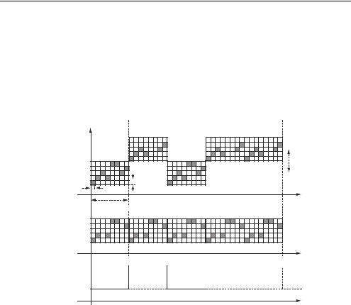
Example 7.1.1. Let us take the FSK signature of Example 5.5.1 and use it for fast FH spreading in combination with a binary FSK data modulation. In this case the number of different frequencies in a signature M ¼ 5, signature length N ¼ 8 and one data symbol transmits one bit, so that T ¼ Tb . Suppose that in a fast FH scheme l ¼ N ¼ 8, i.e. there are 8 frequency hops per data bit. Then the whole sequence of FSK chips shown in Figure 5.3 is transmitted during one bit. If the data bit is zero, this frequency pattern is transmitted on the carrier frequency f0, while for the bit equal to one the carrier frequency jumps to f1. The difference between f1 and f0 should certainly be no smaller than the bandwidth occupied by the signature, i.e. MF. The transmitted frequency pattern corresponding to data bit stream 01011 is shown in Figure 7.11a.
Data bits: 0 |
1 |
0 |
1 |
1 |
|||||
f |
|
|
|
|
|
|
|
|
|
|
|
|
|
|
|
|
|
|
|
|
|
|
|
|
|
|
|
|
|
|
f1 |
|
(a) |
|
MF |
f0 |
|
|
|
|
|
|
∆ |
F |
|
|
t
T = Tb = N∆ 
(b)
f0 – fi 


 t fi + MF


(c)
fi
t
Figure 7.11 Fast FH spreading–despreading
Spread spectrum signature ensembles |
213 |
|
|
As may be seen, the spectrum of a single data bit whose width before spreading was about 1/Tb is spread to span a bandwidth around MF M/D ¼ MN/Tb , i.e. MN times wider (see Section 5.6). At the receiving end despreading consists in down-converting the observed waveform to the intermediate frequency fi . For that the reference waveform of the carrier f0 fi is used, modulated according to a signature FSK pattern, properly delayed in time (Figure 7.11b). As a result a despread signal is an ordinary narrowband FSK data-modulated waveform, where the zero data bit is transmitted by lower frequency than the bit one (Figure 7.11c). The spectrum of an isolated data symbol is now returned to the bandwidth 1/Tb and a conventional binary FSK demodulator may be used to recover the received data.
Let us illustrate in the next example how to run slow FH spreading.
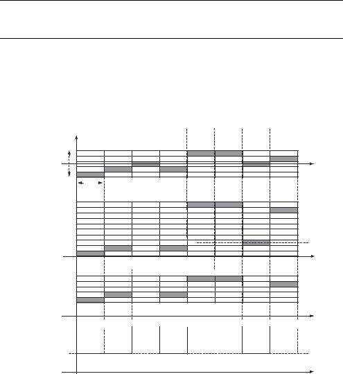
Example 7.1.2. Take the same signature in combination with, again, binary FSK data modulation and set equality between chip and symbol durations: T ¼ Tb ¼ D. This means that the current frequency remains constant over all the data bit duration and frequency hops happen only from one bit to the next. The frequency pattern of the signature is stretched in time and its length now covers N data bits (Figure 7.12a). Suppose that during a data bit number i signature frequency equals Fi . Then the transmitted frequency becomes f0 þ Fi for a zero data
Data bits: 0 |
0 |
1 |
0 |
1 |
1 |
0 |
1 |
f
(a)
MF
t
Tb = ∆
f1 


(b)
f0 


t
(c)
f0 – fi 


fi + MF 


 t
t
(d)
fi
t
Figure 7.12 Slow FH spreading–despreading