


Chapter 6 Neighbor Discovery |
125 |
Neighbor Discovery Message Format
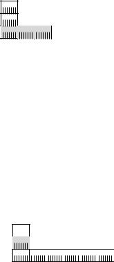
ND messages use the ICMPv6 message structure and ICMPv6 types 133 through 137. ND messages consist of an ND message header, composed of an ICMPv6 header and ND messagespecific data, and zero or more ND options. Figure 6-1 shows the format of an ND message.
IPv6 Header |
|
Neighbor Discovery |
Neighbor Discovery |
||
Next Header = 58 |
|
Message Header |
Message Options |
||
|
|
|
|
|
|
(ICMPv6) |
|
|
|
|
|
|
|
|
|
|
|
|
|
|
Neighbor Discovery Message |
|
|
|
|
|
|
||
|
|
|
|||
Figure 6-1 The format of an ND message
There are five different ND messages:
■Router Solicitation (ICMPv6 type 133)
■Router Advertisement (ICMPv6 type 134)
■Neighbor Solicitation (ICMPv6 type 135)
■Neighbor Advertisement (ICMPv6 type 136)
■Redirect (ICMPv6 type 137)
ND message options provide additional information, indicating MAC addresses, on-link network prefixes, on-link MTU information, redirection data, mobility information, and specific routes.
To ensure that ND messages that are received have originated from a node on the local link (either a physical link or a tunnel), all ND messages are sent with a hop limit of 255. When an ND message is received, the Hop Limit field in the IPv6 header is checked. If it is not set to 255, the message is silently discarded. Verifying that the ND message has a hop limit of 255 provides protection from ND-based network attacks that are launched from off-link nodes. With a hop limit of 255, a router could not have forwarded the ND message from an off-link node.
Neighbor Discovery Options
ND options are formatted in type-length-value (TLV) format. Figure 6-2 shows the TLV format.
Type 
Length
Value
• • •
Figure 6-2 The TLV format for ND options

126 Understanding IPv6, Second Edition
The 8-bit Type field indicates the type of ND option. Table 6-1 lists the ND option types defined in RFC 4861, RFC 3775, and RFC 4191.
Table 6-1 IPv6 ND Option Types
Type |
Option Name |
Source Document |
1 |
Source Link-Layer Address |
RFC 4861 (Neighbor Discovery for IPv6) |
|
|
|
2 |
Target Link-Layer Address |
RFC 4861 |
|
|
|
3 |
Prefix Information |
RFC 4861 |
|
|
|
4 |
Redirected Header |
RFC 4861 |
|
|
|
5 |
MTU |
RFC 4861 |
|
|
|
7 |
Advertisement Interval |
RFC 3775 (Mobile IPv6) |
|
|
|
8 |
Home Agent Information |
RFC 3775 |
|
|
|
24 |
Route Information |
RFC 4191 (Default Router Preferences and More- |
|
|
Specific Routes) |
|
|
|
The 8-bit Length field indicates the length of the entire option in 8-byte blocks. All ND options must fall on 8-byte boundaries. The variable length Value field contains the data for the option.
The Advertisement Interval and Home Agent Information options are described in Appendix F, “Mobile IPv6.”
Source and Target Link-Layer Address Options
The Source Link-Layer Address option indicates the link-layer address of the ND message sender. The Source Link-Layer Address option is included in the Neighbor Solicitation, Router Solicitation, and Router Advertisement messages. The Source Link-Layer Address option is not included when the source address of the ND message is the unspecified address (::).
Figure 6-3 shows the structure of the Source Link-Layer Address option.
Type  = 1
= 1
Length 
Link-Layer Address
• • •
Figure 6-3 The structure of the Source Link-Layer Address option
The Target Link-Layer Address option indicates the link-layer address of the neighboring node to which IPv6 packets should be directed. The Target Link-Layer Address option is included in the Neighbor Advertisement and Redirect messages.
Figure 6-4 shows the structure of the Target Link-Layer Address option.
Chapter 6 Neighbor Discovery |
127 |
Type  = 2
= 2
Length 
Link-Layer Address
• • •
Figure 6-4 The structure of the Target Link-Layer Address option
The Source Link-Layer Address option and the Target Link-Layer Address option have the same format.
The Type field is set to 1 for a Source Link-Layer Address option and 2 for a Target Link-Layer Address option. The Length field is set to the number of 8-byte blocks in the entire option. The Link-Layer Address field is a variable-length field that contains the link-layer address of the source or target. Each link layer defined for IPv6 must specify the way in which the linklayer address is formatted in the Source and Target Link-Layer Address options.
For example, RFC 2464 defines how IPv6 packets are sent over Ethernet networks. It also includes the format of the Source and Target Link-Layer Address ND options. For Ethernet, the link-layer address is 48 bits (6 bytes) in length. Figure 6-5 shows the Target Link-Layer Address option for Ethernet.
Type |
|
= 2 |
||
Length |
|
|
= 1 |
|
Ethernet MAC Address 


Figure 6-5 The Target Link-Layer Address option for Ethernet
Network Monitor Capture
Here is an example of a Source Link-Layer Address option used in a Neighbor Solicitation message as displayed by Network Monitor 3.1 (frame 1 of capture 06_01 in the \NetworkMonitorCaptures folder on the companion CD-ROM):
Frame:
+Ethernet: Etype = IPv6
+Ipv6: Next Protocol = ICMPv6, Payload Length = 32
- Icmpv6: Neighbor Solicitation, Target = FE80:0:0:0:260:97FF:FE02:6EA5 MessageType: Neighbor Solicitation, 135(0x87)
-NeighborSolicitation: Code: 0 (0x0) Checksum: 3893 (0xF35) Reserved: 0 (0x0)
TargetAddress: FE80:0:0:0:260:97FF:FE02:6EA5
-SourceLinkLayerAddress:
Type: Source Link-Layer Address, 1(0x1)
Length: 1, in unit of 8 octets
Address: 00-10-5A-AA-20-A2
128 Understanding IPv6, Second Edition
Prefix Information Option
The Prefix Information option is sent in Router Advertisement messages to indicate both address prefixes and information about address autoconfiguration. There can be multiple Prefix Information options included in a Router Advertisement message, indicating multiple address prefixes.
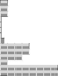
Figure 6-6 shows the structure of the Prefix Information option.
Type |
= 3 |
Length |
= 4 |
Prefix Length |
|
On-Link Flag |
|
Autonomous Flag |
|
Router Address Flag |
|
Site Prefix Flag |
|
Reserved 1 |
|
Valid Lifetime |
|
Preferred Lifetime |
|
Reserved 2 |
|
Site Prefix Length |
|
Prefix |
|
Figure 6-6 The structure of the Prefix Information option
The fields in the Prefix Information option are as follows:
■Type The value of this field is 3.
■Length The value of this field is 4. (The entire option is 32 bytes in length.)
■Prefix Length The Prefix Length field indicates the number of leading bits in the Prefix field that make up the address prefix. The size of this field is 8 bits. The Prefix Length field has a value from 0 through 128. Because typical prefixes advertised are for subnet identifiers, the Prefix Length field is usually set to 64.
■On-Link flag The On-Link flag indicates, when set to 1, that the addresses implied by the included prefix are available on the link on which this Router Advertisement message was received. When this flag is set to 0, it is not assumed that the addresses that match the prefix are available on-link. The size of this field is 1 bit.
■Autonomous flag The Autonomous flag indicates, when set to 1, that the included prefix is used to create an autonomous (or stateless) address configuration. When this flag is set to 0, the included prefix is not used to create a stateless address configuration. The size of this field is 1 bit.
■Router Address flag The Router Address flag is defined in RFC 3775 for Mobile IPv6. For more information, see Appendix F.
Chapter 6 Neighbor Discovery |
129 |
■Site Prefix flag The Site Prefix flag indicates, when set to 1, that the site prefix defined by the Prefix field and the Site Prefix Length field be used to update the site prefix table. The site prefix table is maintained by the host and is utilized to prefer the use of site-local addresses when a global address matches a site prefix. This flag is described in the Internet draft titled “Site Prefixes in Neighbor Discovery.”
■Reserved1 The Reserved1 field is a 4-bit field reserved for future use and set to 0.
■Valid Lifetime The Valid Lifetime field indicates the number of seconds that an address, based on the included prefix and using stateless address configuration, remains valid. The size of this field is 32 bits. The Valid Lifetime field also indicates the number of seconds that the included prefix is valid for on-link determination. For an infinite valid lifetime, the Valid Lifetime field is set to 0xFFFFFFFF.
■Preferred Lifetime The Preferred Lifetime field indicates the number of seconds that an address, based on the included prefix and using stateless address autoconfiguration, remains in a preferred state. The size of this field is 32 bits. Stateless autoconfiguration addresses that are still valid are either in a preferred or deprecated state. In the preferred state, the address can be used for unrestricted communication. In the deprecated state, the use of the address is not recommended for new communications. However, existing communications using a deprecated address can continue. An address goes from the preferred state to the deprecated state when its preferred lifetime expires. For an infinite preferred lifetime, the Preferred Lifetime field is set to 0xFFFFFFFF.
■Reserved2 The Reserved2 field is a 24-bit field reserved for future use and set to 0.
■Site Prefix Length The Site Prefix Length field indicates the number of leading bits in the Prefix field that define a site prefix. The length of this field is 8 bits. This field is significant only if the Site Prefix flag is set to 1. This field is described in the Internet draft titled “Site Prefixes in Neighbor Discovery.”
■Prefix The Prefix field indicates the prefix for the IPv6 address derived through stateless autoconfiguration. The size of this field is 128 bits. Bits in the Prefix field—up to a count equaling the value of the Prefix Length field—are significant for creating the prefix. The combination of the Prefix Length field and the Prefix field unambiguously defines the prefix which, when combined with the interface identifier for the node, creates an IPv6 address. The link-local prefix should not be sent and is ignored by the receiving host.
Network Monitor Capture
Here is an example of a Prefix Information option used in a Router Advertisement message as displayed by Network Monitor 3.1 (capture 06_02 in the \NetworkMonitorCaptures folder on the companion CD-ROM):
Frame:
+Ethernet: Etype = IPv6
+Ipv6: Next Protocol = ICMPv6, Payload Length = 96 - Icmpv6: Router Advertisement
MessageType: Router Advertisement, 134(0x86)