
- •Contents
- •Course Overview
- •Course Agenda
- •Document Conventions
- •Additional Information
- •Chapter 1: Course Introduction
- •Chapter 2: Junos Operating System Fundamentals
- •The Junos OS
- •Traffic Processing
- •Overview of Junos Devices
- •Chapter 3: User Interface Options
- •User Interface Options
- •The Junos CLI: CLI Basics
- •The Junos CLI: Operational Mode
- •The Junos CLI: Configuration Mode
- •Lab 1: The Junos CLI
- •Chapter 4: Initial Configuration
- •Factory-Default Configuration
- •Initial Configuration
- •Interface Configuration
- •Lab 2: Initial System Configuration
- •Chapter 5: Secondary System Configuration
- •User Configuration and Authentication
- •System Logging and Tracing
- •Network Time Protocol
- •Archiving Configurations
- •SNMP
- •Lab 3: Secondary System Configuration
- •Monitoring Platform and Interface Operation
- •Network Utilities
- •Maintaining the Junos OS
- •Password Recovery
- •Lab 4: Operational Monitoring and Maintenance
- •Appendix A: Interface Configuration Examples
- •Review of the Interface Configuration Hierarchy
- •Interface Configuration Examples
- •Using Configuration Groups
- •Appendix B: The J-Web Interface
- •Configuration
- •Lab 5 (Optional): The J-Web Interface
- •Appendix C: Acronym List
- •Appendix D: Answer Key
- •Chapter 1: Course Introduction
- •Chapter 2: Junos Operating System Fundamentals
- •Chapter 3: User Interface Options
- •Chapter 4: Initial Configuration
- •Chapter 5: Secondary System Configuration
- •Chapter 6: Operational Monitoring and Maintenance
Introduction to the Junos Operating System
Interface Configuration
The slide highlights the topic we discuss next.
Chapter 4–18 • Initial Configuration |
www.juniper.net |
Introduction to the Junos Operating System
Interface Overview
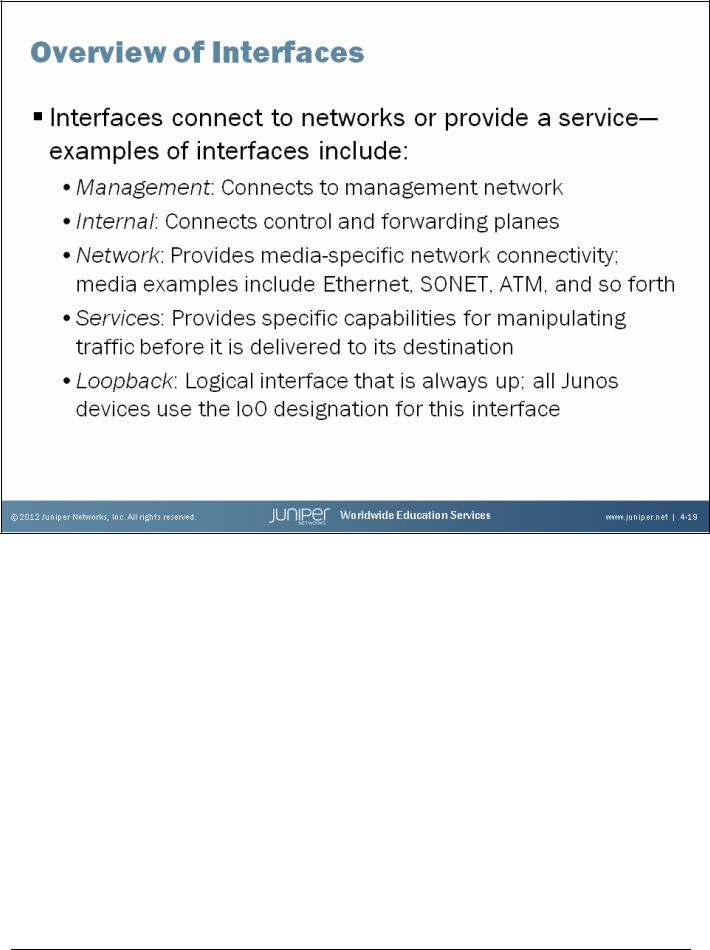
Interfaces are primarily used to connect a device to a network; however, some interfaces are used to provide a service or a specific function for the system on which it operates. On platforms running the Junos OS, several types of interfaces exist, including:
•Management interfaces: Used to connect the device running the Junos OS to a management network. The actual designation for this interface is platform-specific; examples include fxp0 and me0.
•Internal interfaces: Used to connect the control and forwarding planes. The actual designation for this interface is platform-specific; examples include fxp1 and em0.
•Network interfaces: Used to provide media-specific network connectivity. Some media examples include Ethernet, SONET, Asynchronous Transfer Mode (ATM), T1, and DS3. We cover examples of network interfaces on subsequent pages within this chapter.
Continued on the next page.
www.juniper.net |
Initial Configuration • Chapter 4–19 |

Introduction to the Junos Operating System
Interface Overview (contd.)
•Services interfaces: Used to provide one or more user-configurable services such as encryption, tunneling, and link services. Services interfaces can be provided through a physical services interface card or through software. Services interfaces provided through a PIC do not have ports or media associated with them, but have two-letter interface type designations as shown in the list that follows (actual coverage of the services provided by these interfaces is beyond the scope of this class):
–es: Encryption interface;
–gr: Generic route encapsulation tunnel interface;
–ip: IP-over-IP encapsulation tunnel interface;
–ls: Link services interface;
–ml: Multilink interface;
–mo: Passive monitoring interface;
–mt: Multicast tunnel interface;
–sp: Adaptive services interface; and
–vt: Virtual loopback tunnel interface.
•Loopback interfaces: Used to provide a constant and dependable hardware-independent interface. The loopback interface uses the lo0 designation on all platforms running the Junos OS. Use the lo0 interface in conjunction with routing protocols to facilitate routing in a redundant environment that is independent of the individual physical links within that environment. You can configure a single logical unit for the lo0 interface for each routing instance. Each logical unit associated with a given routing instance can, however, have multiple configured IP addresses.
Chapter 4–20 • Initial Configuration |
www.juniper.net |
Introduction to the Junos Operating System
Interface Naming
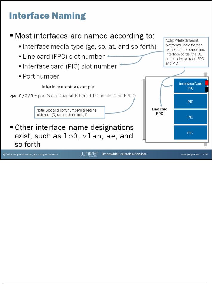
The Junos OS uses a standard naming convention. Most interfaces have names based on the interface media type, the system slot number in which the line card is installed, the line card slot number in which the interface card is installed, and the port number for the interface card. As noted on the slide, the CLI almost always refers to line cards as Flexible PIC Concentrators (FPCs) and interface cards as PICs even though the actual names of these physical components might vary between Junos devices. For platform-specific information, including details pertaining to the interface naming convention for your specific device, see http://www.juniper.net/techpubs/ for the technical publications.
In typical deployments, the slot and port numbering begins with zero (0) and increments based on the system hardware configuration. The slide shows a sample interface name that illustrates the interface naming format. The highlighted interface name is for the fourth physical port (number 3) on a Gigabit Ethernet interface card installed in the third slot (number 2) of a line card that resides on the first available line card slot (number 0) of a chassis.
Continued on the next page.
www.juniper.net |
Initial Configuration • Chapter 4–21 |

Introduction to the Junos Operating System
Other Interface Name Designations
As mentioned on the slide, other interface name designations exist that do not adhere to the naming convention illustrated on the top of the slide. Interfaces with specific designations are created by the Junos OS and are not directly associated with or dependent on physical interfaces. The following are some examples:
•lo0: Loopback interface;
•ae: Aggregated Ethernet interface;
•as: Aggregated SONET interface; and
•vlan: VLAN interface.
The Junos OS also creates a number of internal interfaces. These internally generated interfaces are nonconfigurable. The following are some examples:
•gre;
•mtun;
•ipip; and
•tap.
Note that interface support varies between the different Junos devices. For support information, always refer to the technical documentation for your specific product.
Chapter 4–22 • Initial Configuration |
www.juniper.net |
Introduction to the Junos Operating System
Logical Interfaces
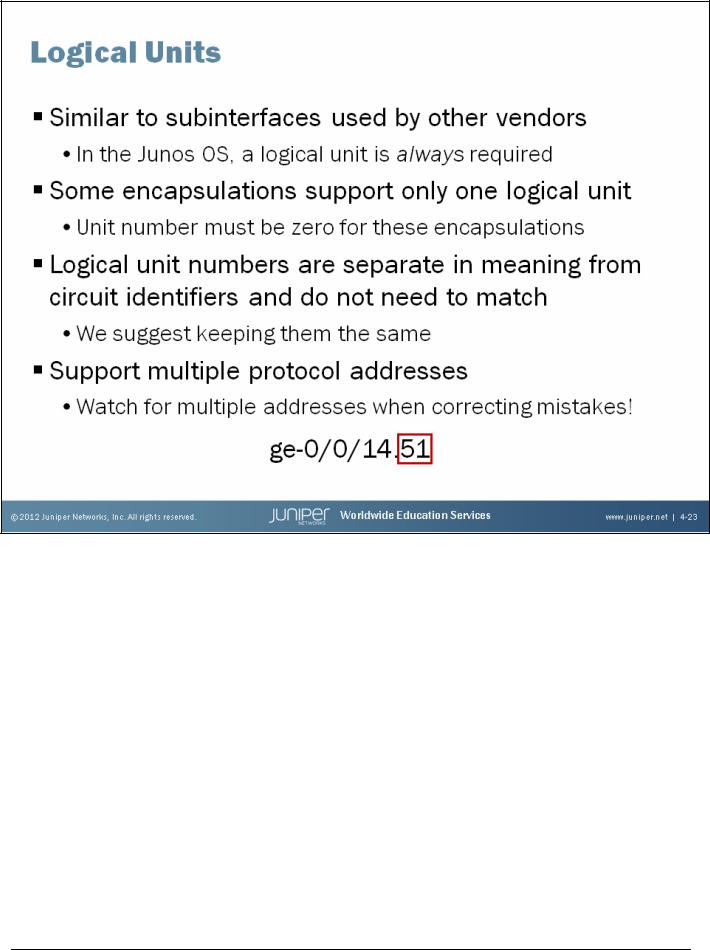
Each physical interface descriptor can contain one or more logical interface descriptors. These descriptors allow you to map one or more logical (sometimes called virtual) interfaces to a single physical device. Creating multiple logical interfaces is useful in environments where multiple virtual circuits or Data Link Layer connections are associated with a single physical interface, such as in ATM and Frame Relay networks.
Logical Units and Encapsulation
Some encapsulations, such as the Point-to-Point Protocol (PPP) and the Cisco High-Level Data Link Control (Cisco HDLC) protocol, support only a single logical interface, and its logical unit number must be zero. Other encapsulations, such as Frame Relay, ATM, and tagged Ethernet, support multiple logical interfaces, so you can configure one or more logical unit numbers.
Continued on the next page.
www.juniper.net |
Initial Configuration • Chapter 4–23 |

Introduction to the Junos Operating System
Circuit Identifier Versus Unit Number
The unit number and the circuit identifier are different in meaning. The circuit identifier identifies the logical tunnel or circuit, whereas the unit is used to identify a logical partition of the physical interface.
Although not required, it is generally considered best practice to keep the unit number and circuit identifier the same. This practice can greatly aid in troubleshooting when you have many logical circuits.
Multiple Addresses
Junos devices can have more than one address on a single logical interface. Issuing a second set command does not overwrite the previous address but rather adds an additional address under the logical unit. Use of the CLI’s rename command is an excellent way to correct addressing mistakes. The following is an example:
[edit interfaces ge-0/0/1 unit 0] user@router# set family inet address 10.1.1.1
[edit interfaces ge-0/0/1 unit 0] user@router# show
family inet {
address 10.1.1.1/32;
}
[edit interfaces ge-0/0/1 unit 0]
user@router# rename family inet address 10.1.1.1/32 to address 10.1.1.1/24
[edit interfaces ge-0/0/1 unit 0] user@router# show
family inet {
address 10.1.1.1/24;
}
Also note that the Junos OS forms interior gateway protocol (IGP) adjacencies over all subnets when the IGP is configured on a logical interface; this behavior is worth noting because some vendors form an adjacency over only the primary address of an interface.
Chapter 4–24 • Initial Configuration |
www.juniper.net |
Introduction to the Junos Operating System
Physical Properties
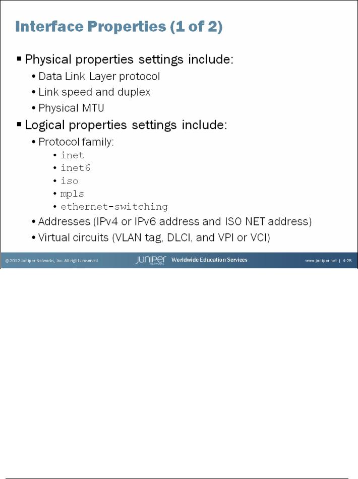
The following list provides details for some physical interface properties.
•Data Link Layer protocol and keepalives: You can change the Data Link Layer protocol for the particular media type (for example, PPP to Cisco HDLC), and you can turn keepalives on or off.
•Link mode: On Ethernet interfaces you can hardcode the duplex setting to either half-duplex or full-duplex.
•Speed: You can specify the link speed on certain interface types.
•Maximum transmission unit (MTU): You can vary the size from 256 to 9192 bytes.
•Clocking: Refers to the interface clock source, either internal or external.
•Scrambling: Refers to payload scrambling, which can be on or off.
•Frame check sequence (FCS): You can modify to 32-bit mode (the default is 16-bit mode).
•Diagnostic characteristics: You can enable local or remote loopbacks or set up a BERT test.
Continued on the next page.
www.juniper.net |
Initial Configuration • Chapter 4–25 |

Introduction to the Junos Operating System
Logical Properties
|
The following list provides details for some logical interface properties: |
||
IPv6 support varies |
• |
Protocol family: Refers to the protocol family you want to use, such as family inet, inet6, |
|
between Junos devices |
|
iso, mpls, or ethernet-switching. |
|
and versions. |
• |
Addresses: Refers to the address associated with the particular family (for example, IP |
|
Reference the most |
|||
|
address using family inet). |
||
recent technical |
|
||
|
|
||
publications for |
• |
Virtual circuits: Refers to the virtual circuit identifier, such as a data-link connection |
|
support information. |
|
identifier (DLCI), virtual path identifier (VPI), virtual channel identifier (VCI), or virtual |
|
|
|
LAN (VLAN) tag. |
|
•Other characteristics: Some other configurable options include Inverse ARP, traps, and accounting profiles.
Chapter 4–26 • Initial Configuration |
www.juniper.net |

Introduction to the Junos Operating System
Configuration Hierarchy
All interfaces have the same configuration hierarchy organization. The Junos OS considers all properties defined directly under the interface name to be the physical properties of that interface. The unit number represents a particular logical interface or subinterface. The Junos OS considers all properties defined directly under the unit number to be the logical properties of each particular subinterface.
www.juniper.net |
Initial Configuration • Chapter 4–27 |
Introduction to the Junos Operating System
Configuration Example
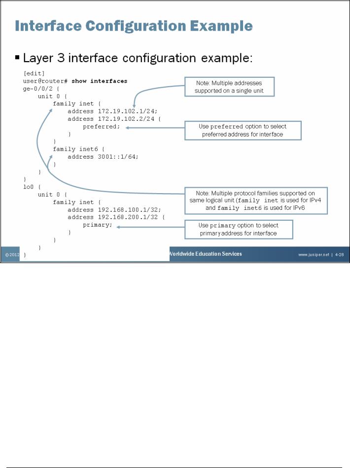
The slide provides a basic configuration example that includes multiple interfaces, multiple protocol families configured under a single logical unit, and multiple IP addresses configured for a single protocol family.
While a single logical unit does support multiple protocol families, such as inet and inet6, you cannot configure a second protocol family in conjunction with the ethernet-switching protocol family. The following example illustrates this point:
[edit]
user@router# commit
[edit interfaces ge-0/0/2 unit 0] 'family'
When ethernet-switching family is configured on an interface, no other family type can be configured on the same interface.
error: configuration check-out failed
The example on the slide also highlights the use of the preferred and primary configuration options. The preferred option is used when you have multiple IP addresses belonging to the same subnet on the same interface. This option allows you to select which address will be used as the source address for packets sent by the local system to hosts on the directly connected subnet. By default, the numerically lowest local address is chosen. In the example on the slide, the default behavior has been overridden with the preferred option making 172.19.102.2/24 the preferred address.
Continued on the next page.
Chapter 4–28 • Initial Configuration |
www.juniper.net |

Introduction to the Junos Operating System
Configuration Example (contd.)
The primary address on an interface is the address that is used by default as the local address for broadcast and multicast packets sourced locally and sent out the interface. The primary address flag also can be useful for selecting the local address used for packets sent out unnumbered interfaces when multiple non-127 addresses are configured on the loopback interface, lo0. By default, the primary address on an interface is selected as the numerically lowest local address configured on the interface. In the example on the slide, 172.19.102.1/24 is the primary address for the ge-0/0/ 2.0 interface, because it is the numerically lowest address configured on that interface; 192.168.200.1/32 is the primary address for the lo0.0 interfaces, because it has the primary option. The following capture verifies the primary state:
user@router> show interfaces ge-0/0/2.0 | find addresses
Addresses, Flags: Is-Primary
Destination: 172.19.102/24, Local: 172.19.102.1, Broadcast: 172.19.102.255
Addresses, Flags: Preferred Is-Preferred Destination: 172.19.102/24, Local: 172.19.102.2, Broadcast: 172.19.102.255
Protocol inet6, MTU: 1500 Flags: Is-Primary
Addresses, Flags: Is-Default Is-Preferred Is-Primary Destination: 3001::/64, Local: 3001::1
Addresses, Flags: Is-Preferred
Destination: fe80::/64, Local: fe80::217:cbff:fe4e:ab02
user@router> show interfaces lo0.0 | find addresses
Addresses
Local: 192.168.100.1
Addresses, Flags: Primary Is-Default Is-Primary Local: 192.168.200.1
Interface support varies between Junos devices. Refer to the technical publications for detailed information for your specific product.
For additional interface configuration examples, refer to Appendix A.
www.juniper.net |
Initial Configuration • Chapter 4–29 |
Introduction to the Junos Operating System
Tracking the State of an Interface
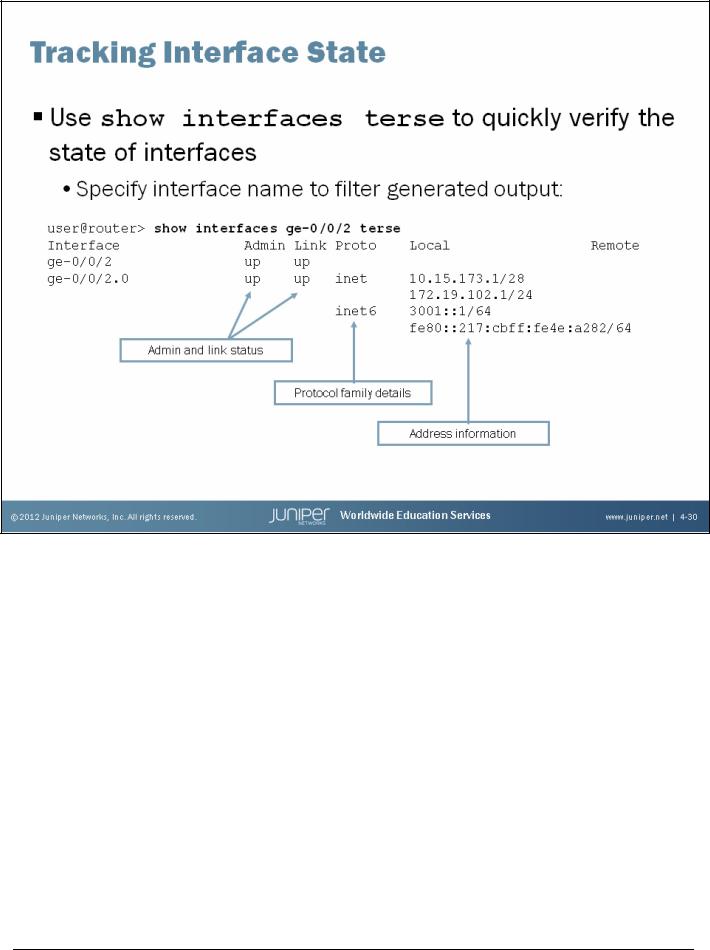
To quickly verify the state of an interface you can issue the show interfaces terse command. To filter the displayed output to an individual interface, add the name of the interface, as shown on the slide. In the sample output displayed on the slide, we see the admin and link status, the protocol family details, and the address information for the specified interface. We cover interface monitoring in greater detail in a subsequent chapter.
Chapter 4–30 • Initial Configuration |
www.juniper.net |
Introduction to the Junos Operating System
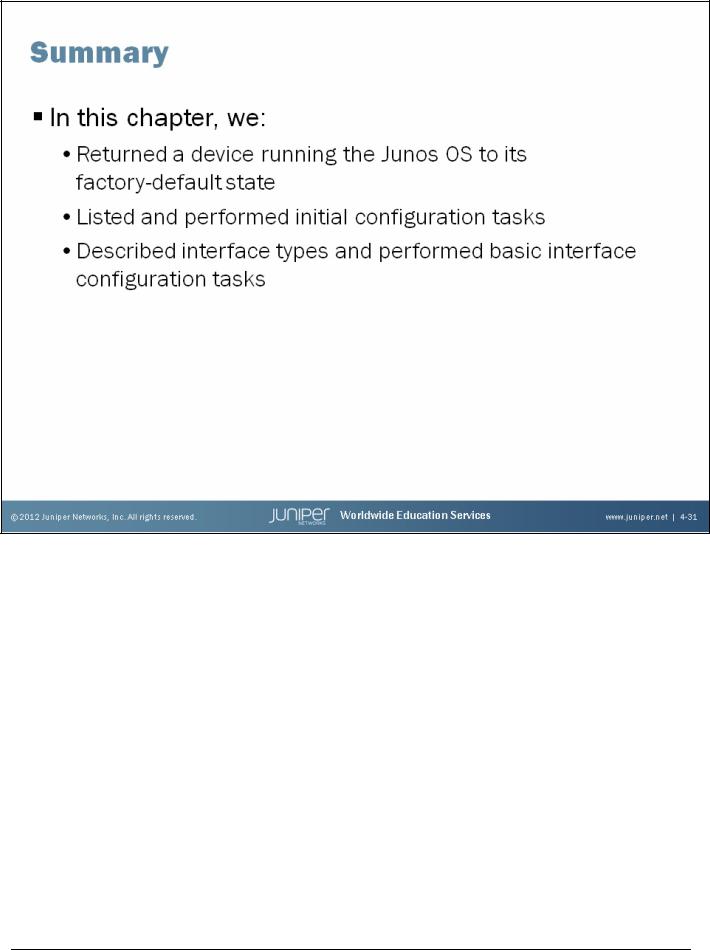
This Chapter Discussed:
•The factory-default configuration for platforms running the Junos OS;
•Initial configuration tasks performed on devices running the Junos OS; and
•Interface types and interface configuration basics.
www.juniper.net |
Initial Configuration • Chapter 4–31 |
Introduction to the Junos Operating System
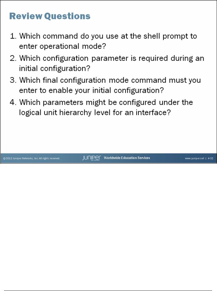
Review Questions
1.
Use the cli command at the shell prompt to enter operational mode.
2.
The root authentication is the only required parameter during the initial configuration.
3.
As always, you must issue a commit for any configuration changes to take effect.
4.
Some examples of logical interface properties you might configure include the protocol family (such as inet, inet6, iso, mpls, or ethernet-switching), addresses, and virtual circuit identifiers (such as VPI, VCI, DLCI, and VLAN tag).
Chapter 4–32 • Initial Configuration |
www.juniper.net |
