

Книги_AutoCad_1 / AutoCAD 2006 VBA_A Programmer’s Reference_Joe Sutphin__2005_
.pdf348 C H A P T E R 1 5 ■ L AYO U T A N D P L OT C O N F I G U R AT I O N S
The CanonicalMediaName Property
You can read or set the paper size to be used when plotting using the CanonicalMediaName property of the Layout or PlotConfiguration object. You specify the paper size by a name given as a string, and changes to this property won’t take effect until the drawing has been regenerated.
Object.CanonicalMediaName = strPaperSize
This code snippet shows how to read the current setting of the paper size for the active layout of a drawing:
Public Sub PaperSizeNames()
MsgBox "The paper size for the active layout is " & _
ThisDrawing.ActiveLayout.CanonicalMediaName
End Sub
The result of this code may be similar to that shown in Figure 15-5.
Figure 15-5. PaperSizeNames output
The GetCanonicalMediaNames Method
You can use the GetCanonicalMediaNames method to retrieve the names of the available paper sizes for a specified plot device. The return value for this method is an array of strings holding the names of the available paper sizes.
varPaperSizeNames = Object.GetCanonicalMediaNames()
It’s advisable to call the RefreshPlotDeviceInfo method before you use this method for the first time, and each time you’re changing the default plot device. This ensures that the plot, paper size names, and plot style table information accurately reflect the current system state.
The GetPaperSize Method
Although you can read the CanonicalMediaName property to find out the name of the paper size to be used, you may want to know the actual width and height dimensions. The GetPaperSize method retrieves the width and height of the configured paper, given in the current paper units.
Object.GetPaperSize Width, Height

C H A P T E R 1 5 ■ L AYO U T A N D P L OT C O N F I G U R AT I O N S |
349 |
Table 15-9 shows the GetPaperSize method’s parameters.
Table 15-9. GetPaperSize Method Parameters
Name |
Data Type |
Description |
Width |
Double |
The width of the paper in units specified by the PaperUnits prop- |
|
|
erty of the layout or plot configuration |
Height |
Double |
The height of the paper in units specified by the PaperUnits prop- |
|
|
erty of the layout or plot configuration |
|
|
|
The following code example incorporates the property and methods associated with the paper size. First, the available paper sizes for the current layout are retrieved and displayed to the user. If the user then enters one of these in an input box, the dimensions of the chosen paper size display.
Public Sub PaperSize()
Dim varPaperSizeNames As Variant
Dim strPaperSizeNames As String
Dim intCount As Integer
Dim strChoosenPaperSize As String
varPaperSizeNames = ThisDrawing.ActiveLayout.GetCanonicalMediaNames strPaperSizeNames = "These are the paper sizes available:" & vbCrLf For intCount = 0 To UBound(varPaperSizeNames)
strPaperSizeNames = strPaperSizeNames & _ varPaperSizeNames(intCount) & ", "
Next intCount
strPaperSizeNames = strPaperSizeNames & vbCrLf & " Please choose one."
strChoosenPaperSize = InputBox(strPaperSizeNames, "Pick a paper size")
For intCount = 0 To UBound(varPaperSizeNames)
If StrComp(strChoosenPaperSize, varPaperSizeNames(intCount), 1) = 0 _ Then GoTo DisplaySize
Next intCount
MsgBox "You did not enter a valid paper size name." Exit Sub
DisplaySize:
Dim dblPaperWidth As Double
Dim dblPaperHeight As Double
Dim lngPaperUnits As Long
Dim strPaperUnits As String

350 C H A P T E R 1 5 ■ L AYO U T A N D P L OT C O N F I G U R AT I O N S
ThisDrawing.ActiveLayout.GetPaperSize dblPaperWidth, dblPaperHeight lngPaperUnits = ThisDrawing.ActiveLayout.PaperUnits
Select Case lngPaperUnits Case 0
strPaperUnits = "inches" dblPaperWidth = dblPaperWidth / 25.4 dblPaperHeight = dblPaperHeight / 25.4
Case 1
strPaperUnits = "millimeters" End Select
MsgBox dblPaperWidth & " by " & dblPaperHeight & " " & strPaperUnits End Sub
The Plot Scale
You normally draw an AutoCAD drawing in units that reflect the true size of the object being represented. Therefore, when you print your drawing you’ll probably need to scale the plot so that it fits comfortably onto the paper. There are two types of plot scales, and both give the ratio of the plot size to drawing size. The first is the standard scale and it’s set to one of AutoCAD’s predefined scales. The second, custom scale, can be set to any value.
The StandardScale Property
You can use the StandardScale property to set the plot scale to one of the predefined AutoCAD scales.
Object.StandardScale = lngAcPlotScale
This must be one of the AcPlotScale constants detailed in Table 15-10.
Table 15-10. AcPlotScale Constants
Constant |
Value |
Description |
acScaleToFit |
0 |
Scale to Fit |
ac1_128in_1ft |
1 |
1/128′′ : 1′ |
ac1_64in_1ft |
2 |
1/64′′ : 1′ |
ac1_32in_1ft |
3 |
1/32′′ : 1′ |
ac1_16in_1ft |
4 |
1/16′′ : 1′ |
ac3_32in_1ft |
5 |
3/32′′ : 1′ |
ac1_8in_1ft |
6 |
1/8′′ : 1′ |
ac3_16in_1ft |
7 |
3/16′′ : 1′ |
ac1_4in_1ft |
8 |
1/4′′ : 1′ |
ac3_8in_1ft |
9 |
3/8′′ : 1′ |
ac1_2in_1ft |
10 |
1/2′′ : 1′ |
ac3_4in_1ft |
11 |
3/4′′ : 1′ |
ac1in_1ft |
12 |
1′′ : 1′ |
ac3in_1ft |
13 |
3′′ : 1′ |

C H A P T E R 1 5 ■ L AYO U T A N D P L OT C O N F I G U R AT I O N S |
351 |
Constant |
Value |
Description |
ac6in_1ft |
14 |
6′′ : 1′ |
ac1ft_1ft |
15 |
1′ : 1′ |
ac1_1 |
16 |
1:1 |
ac1_2 |
17 |
1:2 |
ac1_4 |
18 |
1:4 |
ac1_8 |
19 |
1:8 |
ac1_10 |
20 |
1:10 |
ac1_16 |
21 |
1:16 |
ac1_20 |
22 |
1:20 |
ac1_30 |
23 |
1:30 |
ac1_40 |
24 |
1:40 |
ac1_50 |
25 |
1:50 |
ac1_100 |
26 |
1:100 |
ac2_1 |
27 |
2:1 |
ac4_1 |
28 |
4:1 |
ac8_1 |
29 |
8:1 |
ac10_1 |
30 |
10:1 |
ac100_1 |
31 |
100:1 |
|
|
|
The GetCustomScale Method
You use this method to examine the scale for a layout or plot configuration.
Object.GetCustomScale(Numerator, Denominator)
Table 15-11 shows the GetCustomScale method’s parameters.
Table 15-11. GetCustomScale Method Parameters
Name |
Data Type |
Description |
Numerator |
Double |
The numerator in the scale ratio. This value represents the |
|
|
number of inches or millimeters for the plot. The unit of |
|
|
measurement is held in the PaperUnits parameter. |
Denominator |
Double |
The denominator in the scale ratio. This value represents the |
|
|
number of drawing units used to scale to the measurement |
|
|
given in the numerator. |
|
|
|
You can use the following code to retrieve the scales used in each of the layouts of your drawing:
Public Sub GetScales()
Dim objLayout As AcadLayout
Dim dblNumerator As Double
Dim dblDenominator As Double

352 C H A P T E R 1 5 ■ L AYO U T A N D P L OT C O N F I G U R AT I O N S
For Each objLayout In ThisDrawing.Layouts 'Get custom scale information
objLayout.GetCustomScale dblNumerator, dblDenominator If objLayout.PaperUnits = acInches Then
MsgBox "The scale of " & objLayout.Name & _
" is " & dblNumerator & " inches = " & _ dblDenominator & " Drawing Units"
ElseIf objLayout.PaperUnits = acMillimeters Then MsgBox "The scale of " & objLayout.Name & _
" is " & dblNumerator & " millimeters = " & _ dblDenominator & " Drawing Units"
Else
MsgBox "The scale of " & objLayout.Name & " is " & _ dblNumerator & " pixels = " & dblDenominator & _ " Drawing Units"
End If Next
End Sub
The SetCustomScale Method
This method works in a similar way to GetCustomScale, described previously, except it sets the plot scale. Any changes you make through this method become effective only after the drawing has been regenerated.
Object.SetCustomScale(Numerator, Denominator)
Table 15-12 shows the SetCustomScale method’s parameters.
Table 15-12. SetCustomScale Method Parameters
Name |
Data Type |
Description |
Numerator |
Double |
A positive value representing the number of inches or milli- |
|
|
meters of the plot. The unit of measurement is held in the |
|
|
PaperUnits parameter. |
Denominator |
Double |
A positive value representing the number of drawing units for |
|
|
the drawing that will be scaled to the measurement given in the |
|
|
numerator. |
|
|
|
The UseStandardScale Property
You use this property to read or set whether a plot should use a standard or custom scale. It holds a Boolean value that is set to True if a standard scale is in use or False if a custom plot scale is in use.
Object.UseStandardScale = blnStandardScale
The following code sample employs the UseStandardScale property to retrieve the type of scale used for each layout and displays that information to the user:

C H A P T E R 1 5 ■ L AYO U T A N D P L OT C O N F I G U R AT I O N S |
353 |
Public Sub UseStandardScale()
Dim objLayout As AcadLayout
For Each objLayout In ThisDrawing.Layouts If objLayout.UseStandardScale Then
MsgBox "The scale of " & objLayout.Name & " is a Standard scale"
Else
MsgBox "The scale of " & objLayout.Name & " is a Custom scale" End If
Next End Sub
The PlotRotation Property
If you want to plot a layout at an angle other than the default of 08, then you’ll need to specify the angle of rotation using the PlotRotation property. This property allows you to select predefined angles of 08, 908, 1808, and 2708, measured counterclockwise in the XY plane from the X-axis of the WCS. Changes to the PlotRotation property won’t take effect until the drawing has been regenerated.
Object.PlotRotation = lngAcPlotRotation
Any AcPlotRotation constant shown in Table 15-13 is an acceptable value for this property.
Table 15-13. AcPlotRotation Constants
Constant |
Value |
Description |
ac0degrees |
0 |
The layout and plot have the same orientation. |
ac90degrees |
1 |
The plot is rotated by an angle of 90° from the layout. |
ac180degrees |
2 |
The plot is rotated by an angle of 180° from the layout. |
ac270degrees |
3 |
The plot is rotated by an angle of 270° from the layout. |
|
|
|
In the following code sample, the user is asked at which angle he or she would like to preview the active layout. The preview then displays, and finally the PlotRotation property returns to its original value.
Public Sub PlotAngle()
Dim strPlotAngle As String
Dim lngStoreAngle As Long
lngStoreAngle = ThisDrawing.ActiveLayout.PlotRotation
strPlotAngle = InputBox("For a plot preview please enter the angle" & _ "(in degrees: 0, 90, 180 or 270) that you would like" & _ " your layout plotted at", , "0")

354 C H A P T E R 1 5 ■ L AYO U T A N D P L OT C O N F I G U R AT I O N S
Select Case strPlotAngle
Case "0"
ThisDrawing.ActiveLayout.PlotRotation = ac0degrees
Case "90"
ThisDrawing.ActiveLayout.PlotRotation = ac90degrees
Case "180"
ThisDrawing.ActiveLayout.PlotRotation = ac180degrees
Case "270"
ThisDrawing.ActiveLayout.PlotRotation = ac270degrees
Case Else
MsgBox "You entered an invalid value"
Exit Sub
End Select
ThisDrawing.Regen acActiveViewport
ThisDrawing.Plot.DisplayPlotPreview acFullPreview
ThisDrawing.ActiveLayout.PlotRotation = lngStoreAngle
ThisDrawing.Regen acActiveViewport
End Sub
Summary
In this chapter you explored several topics specific to plotting. This is one area in which AutoCAD 2000 and later versions are vastly different from previous versions. In AutoCAD 2000 and higher, Autodesk added a lot of plotting power, and when you’re programming your plotting applications, the use of plot configuration files can reduce the amount of hard coding required by taking advantage of the features built into the AutoCAD product. Some differences exist between AutoCAD 2000, 2000i, 2002, 2004, 2005, and 2006 as far as programmatic capabilities with respect to plotting and plot configuration management, be sure to refer to the appropriate documentation for your platform.

C H A P T E R 1 6
■ ■ ■
Controlling Menus and
Toolbars
AutoCAD 2000 (and higher) gives you the ability to control the menus and toolbars programmatically. You can manipulate existing menus or create new entries using the objects exposed by the AutoCAD object model. Although you can’t create a completely new menu structure programmatically, you can make changes to the existing menus.
This chapter covers the following topics in detail:
•Loading, saving, and unloading menu groups
•Assigning accelerator keys
•Manipulating the menu bar
•Creating and editing menus
•Creating and editing toolbars
•Floating and docking toolbars
In AutoCAD 2006, the menu system has been radically changed. The system looks the same externally, but the internal functioning of the system and the files the system uses have been overhauled. Fortunately, this is invisible to most VBA programs, as most of the objects and methods have not changed. However, if you want your programs to work with both 2006 and earlier releases, you should know about some of the differences.
•In AutoCAD 2005 and earlier, the menus are stored in .mnu, .mns, .mnc, and .mnr files. AutoCAD 2006 uses just .cui and .mnr files. In AutoCAD 2006, when a partial menu is loaded using the MENULOAD command or the CUILOAD command, a pointer to the partial menu is stored in the current main .cui file.
•AutoCAD 2006 can load existing .mnu or .mns files, at which point they are converted to
.cui files. Subsequent modification to the menus in AutoCAD 2006 will update only the
.cui files.
•.cui files are stored in XML format. Although XML documentation is readily available, the .cui file structure itself is not documented. Unlike the situation with .mnu and .mns from earlier releases, Autodesk strongly discourages creating or editing .cui files manually. Instead, users are expected to use AutoCAD 2006’s new CUI command to perform all .cui file modifications using a dialog box interface.
355

356C H A P T E R 1 6 ■ C O N T R O L L I N G M E N U S A N D TO O L B A R S
•AutoCAD 2006 introduces the concept of work spaces. These are collections of menu settings, specifying the order of pull-downs, location, and visibility of toolbars, and so on. The work spaces are stored in the current main .cui file. Unfortunately, there is no ActiveX access to work spaces.
•In AutoCAD 2005 and earlier, there is only one main menu and many partial menus. In AutoCAD 2006, there are Main and Enterprise (read-only) menus, each of which can
have partial menus attached. To attach menus to the Enterprise menu, it is necessary to temporarily make it the Main menu while using the CUILOAD command. Unfortunately, there is no ActiveX access to the Enterprise menu setting. The user has to change this in the Options dialog box.
In summary, the AutoCAD 2006 menu overhaul, while introducing some useful concepts, has placed various obstacles in the way of the VBA programmer’s ability to safely make changes to the menu system. In light of these problems, you may want to consider using AutoCAD’s CUI interface to create partial menus for your users, rather than doing it under program control as described in this chapter. If you still want VBA control over your AutoCAD 2006 menus, read on.
■Note This chapter’s content is specific to AutoCAD 2000 and later. The previous object models didn’t expose any objects to deal with menus and toolbars.
I will start this chapter with the MenuGroups collection because it’s the parent object of the MenuGroup object, which in turn is the parent object of the ToolBars and PopupMenus collections. The MenuBar collection holds all the PopupMenu objects that are currently displayed in the AutoCAD menu bar.
The MenuGroups Collection
The menus loaded into the current session of AutoCAD are contained in the MenuGroups collection. These menus, grouped into MenuGroup objects, may or may not be visible on the menu bar, but they’re all still contained within this collection. Each MenuGroup object provides access to the toolbars and pop-up menus available within an AutoCAD session.
Loading Menu Groups
You can use the Load method of the MenuGroups collection to load a new menu group contained in a menu file (.mnc, .mns, .mnu, or .cui) into an AutoCAD session.
Set MenuGroupObject = MenuGroupsCollection.Load (MenuFileName [,BaseMenu])
Table 16-1 shows the Load method’s parameters.
C H A P T E R 1 6 ■ C O N T R O L L I N G M E N U S A N D TO O L B A R S |
357 |
Table 16-1. The Load Method’s Parameters
Name |
Data Type |
Description |
MenuFileName |
String |
The path and file name of the menu file to be loaded. |
BaseMenu |
Boolean |
This optional parameter determines whether the menu group |
|
|
is loaded as a base or partial menu. If it’s set to True, then the |
|
|
menu group is loaded as a base menu. Otherwise, the menu |
|
|
group is loaded as a partial menu. The default is False. |
|
|
|
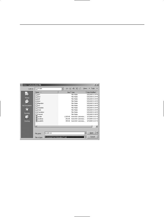
Using the Load method with the BaseMenu parameter set to True equates to executing the MENU command inside the AutoCAD application and selecting a file through the Select Customization File dialog box (see Figure 16-1). Alternatively, you can execute the MENULOAD or CUILOAD command and check the Replace All option in the Menu Customization dialog box (see Figure 16-2). The newly loaded menu file becomes the only loaded menu group and completely replaces the previous menu bar.
Figure 16-1. Using the Select Customization File dialog box to load a menu file