

Книги_AutoCad_1 / AutoCAD 2006 VBA_A Programmer’s Reference_Joe Sutphin__2005_
.pdf228 C H A P T E R 1 0 ■ E D I T I N G O B J E C T S
ThisDrawing.Utility.GetEntity objDrawingObject, varEntityPickedPoint, _ "Pick an entity to change linetype: "
objDrawingObject.Linetype = "Continuous" objDrawingObject.Update
End Sub
■Tip Always use strict error handling should someone assign a nonexistent linetype to an object. If you don’t, your programs will crash. Chapter 6 covers Linetype objects in detail.
Changing an Object’s Visibility
Use the Visible property to set whether a drawing object is visible or not. This method is also available to the Application, Group, and Toolbar objects, although for a Group it is write-only. Set this property True to make an object visible, and False to hide it. Making an object invisible can be useful for performing complex entity creation or modification tasks. This property has the following syntax:
Object.Visible = blnVisible
The following example shows how to implement this method. It hides, and then makes visible, an object.
Public Sub ToggleVisibility()
Dim objDrawingObject As AcadEntity
Dim varEntityPickedPoint As Variant
On Error Resume Next
ThisDrawing.Utility.GetEntity objDrawingObject, varEntityPickedPoint, _ "Choose an object to toggle visibility: "
If objDrawingObject Is Nothing Then MsgBox "You did not choose an object" Exit Sub
End If
objDrawingObject.Visible = False objDrawingObject.Update
MsgBox "The object was made invisible!" objDrawingObject.Visible = True objDrawingObject.Update
MsgBox "Now it is visible again!"
End Sub

C H A P T E R 1 0 ■ E D I T I N G O B J E C T S |
229 |
■Note Other factors, such as whether the object’s layer is frozen or turned off, can override this property.
The Update Method
This chapter and most of this book use the Update method extensively. It forces the AutoCAD graphics display engine to regenerate a specified object on the drawing screen. You need to do this often to accurately reflect changes made to objects.
Summary
This chapter examined several methods and properties you use to edit drawing entities. The next chapter covers adding dimensions and annotations to AutoCAD drawings.


C H A P T E R 1 1
■ ■ ■
Dimensions and Annotations
Although AutoCAD provides an environment that allows users to make detailed and precise drawings, it’s often necessary for users to incorporate further information. A typical user will add textual annotations and measurement annotations (dimensions) to a drawing for manufacturing, modeling, engineering, mapping, and surveying purposes and to help clarify design intent. AutoCAD VBA provides a number of methods to help users create annotations and dimensions that they normally create through the AutoCAD application interface.
In this chapter you’ll learn how to create dimensions and annotations and add them to your drawings. You’ll also see how to set up and use different text and dimension styles.
Working with Dimensions
You add dimension entities to drawings to show the dimension or size of different drawing elements. You can use them to measure angles, distances, and chords. In this section, you’ll examine each of the seven dimension objects in turn. First, however, you’ll look at the DimStyle object, which you use to determine the appearance of dimensions, leaders, and geometric tolerances.
Using the DimStyle Object
The DimStyle object represents some settings that determine the appearance of a dimension, tolerance, or leader. DimStyle objects are held in the DimStyles collection, and you may access them via the DimStyles collection’s Item method.
To create a new DimStyle object through code, you need to use the Add method of the DimStyles collection.
Set DimStyleObject = DimStylesCollection.Add(DimStyleName)
Table 11-1 shows the Add method’s parameter.
Table 11-1. The Add Method’s Parameter
Name |
Data Type |
Description |
DimStyleName |
String |
An identifying name for the new DimStyle object |
231

232 C H A P T E R 1 1 ■ D I M E N S I O N S A N D A N N OTAT I O N S
The following code shows how to add a new DimStyle object:
Dim objDimStyle As AcadDimStyle
Set objDimStyle = ThisDrawing.DimStyles.Add("NewDimStyle")
Setting Dimension Styles
A DimStyle object that is newly created using the Add method inherits the dimension styles of the current active DimStyle object, regardless of any system variable settings that might be overriding the styles of the active DimStyle object. To set the styles for a DimStyle object, you need to set the system variables to reflect your required styles and then use the CopyFrom method explained in the next section.
Using the CopyFrom Method
You use the CopyFrom method to copy to a DimStyle object a set of dimension styles from a dimension, tolerance, leader, document, or another DimStyle object.
DimStyleObject.CopyFrom SourceObject
The SourceObject parameter is the object whose dimension styles are copied. The styles copied depend upon the source object used, as shown in Table 11-2.
Table 11-2. The CopyFrom Method’s Parameters
Object |
Styles Copied |
Dimension, Tolerance, Leader |
The style for that object plus any object overrides |
Document |
The active dimension style settings for the drawing plus any |
|
drawing overrides |
DimStyle |
The style data from that dimension style but no drawing |
|
overrides |
|
|
The following code creates a new dimension style called NewDimStyle. This object inherits all the dimension style properties of the currently active dimension style, except that the color of dimension lines, extension lines, and dimension text are set to red, blue, and white, respectively.
Public Sub NewDimStyle
Dim objDimStyle As AcadDimStyle
Set objDimStyle = ThisDrawing.DimStyles.Add("NewDimStyle") SetVariable "DIMCLRD", acRed
SetVariable "DIMCLRE", acBlue SetVariable "DIMCLRT", acWhite SetVariable "DIMLWD", acLnWtByLwDefault objDimStyle.CopyFrom ThisDrawing
End Sub

C H A P T E R 1 1 ■ D I M E N S I O N S A N D A N N OTAT I O N S |
233 |
Using Dimension Styles
You may associate a dimension style with a particular dimension object by setting its StyleName property, or you may set it to be the currently active style via the ActiveDimStyle property of the Document object. In the latter case, any objects created after the style is made active and not specifically associated with a different dimension style will adopt the style of the active DimStyle object.
■Note No matter which property you use to set the dimension style for an object added to your drawing through code, the newly created object will not adopt any system variable overrides.
The StyleName Property
You use this property to set the dimension style associated with a dimension, tolerance, or leader. To set or change the DimStyle used, simply set or reset the value of this property.
Object.StyleName = DimStyleName
Table 11-3 shows the StyleName property’s parameters.
Table 11-3. The StyleName Property’s Parameters
Name |
Data Type |
Description |
Object |
Dimension, Leader, or Tolerance object |
The object to which the dimension |
|
|
style is linked |
DimStyleName |
String |
The identifying name of the DimStyle |
|
|
object |
|
|
|
The following example asks the user to choose a dimension and changes the style of the dimension to one of the existing dimension styles. The StyleName property of the chosen object is then set appropriately.
Public Sub ChangeDimStyle()
Dim objDimension As AcadDimension
Dim varPickedPoint As Variant
Dim objDimStyle As AcadDimStyle
Dim strDimStyles As String
Dim strChosenDimStyle As String
On Error Resume Next
ThisDrawing.Utility.GetEntity objDimension, varPickedPoint, _
"Pick a dimension whose style you wish to set" If objDimension Is Nothing Then
MsgBox "You failed to pick a dimension object" Exit Sub
End If

234 C H A P T E R 1 1 ■ D I M E N S I O N S A N D A N N OTAT I O N S
For Each objDimStyle In ThisDrawing.DimStyles
strDimStyles = strDimStyles & objDimStyle.Name & vbCrLf Next objDimStyle
strChosenDimStyle = InputBox("Choose one of the following " & _ "Dimension styles to apply" & vbCrLf & strDimStyles)
If strChosenDimStyle = "" Then Exit Sub
objDimension.StyleName = strChosenDimStyle End Sub
The ActiveDimStyle Property
You use the ActiveDimStyle property to make a dimension style the default for any newly created dimension, tolerance, or leader objects. Unlike the ActiveTextStyle property, the ActiveDimStyle property doesn’t affect any preexisting objects.
Set DocumentObject.ActiveDimStyle = DimStyleObject
Table 11-4 shows the ActiveTextStyle property’s parameter.
Table 11-4. The ActiveDimStyle Property’s Parameter
Name |
Data Type |
Description |
DimStyleObject |
DimStyle object |
The object holding the setting for the required dimen- |
|
|
sion style |
|
|
|
The following code displays the current dimension style to the user and provides an opportunity for the user to change it:
Public Sub SetActiveDimStyle()
Dim strDimStyles As String
Dim strChosenDimStyle As String
Dim objDimStyle As AcadDimStyle
For Each objDimStyle In ThisDrawing.DimStyles
strDimStyles = strDimStyles & objDimStyle.Name & vbCrLf
Next
strChosenDimStyle = InputBox("Choose one of the following Dimension " & _ "styles:" & vbCr & vbCr & strDimStyles, "Existing Dimension style is: " & _ ThisDrawing.ActiveDimStyle.Name, ThisDrawing.ActiveDimStyle.Name)
If strChosenDimStyle = "" Then Exit Sub
On Error Resume Next
ThisDrawing.ActiveDimStyle = ThisDrawing.DimStyles(strChosenDimStyle) If Err Then MsgBox "Dimension style was not recognized"
End Sub

C H A P T E R 1 1 ■ D I M E N S I O N S A N D A N N OTAT I O N S |
235 |
Creating Dimensions
Dimension objects are entities that provide information about distances and angles within an AutoCAD drawing. It makes sense then that, just as for the drawing objects covered in Chapters 7 and 8, the AddDimXXX methods used to add dimensions to drawings are exposed by the
ModelSpace, PaperSpace, and Block objects.
It’s worth noting that not all properties of dimension entities are exposed through the ActiveX object model. For example, the dimension line control points of DimAligned objects are available only as DXF 13 and 14 codes. In addition, some dimension objects behave differently between AutoCAD 2002 and 2004 (and later versions), and I will emphasize that developers should research the changes in newer versions, especially with respect to dimensions and dimension styles.
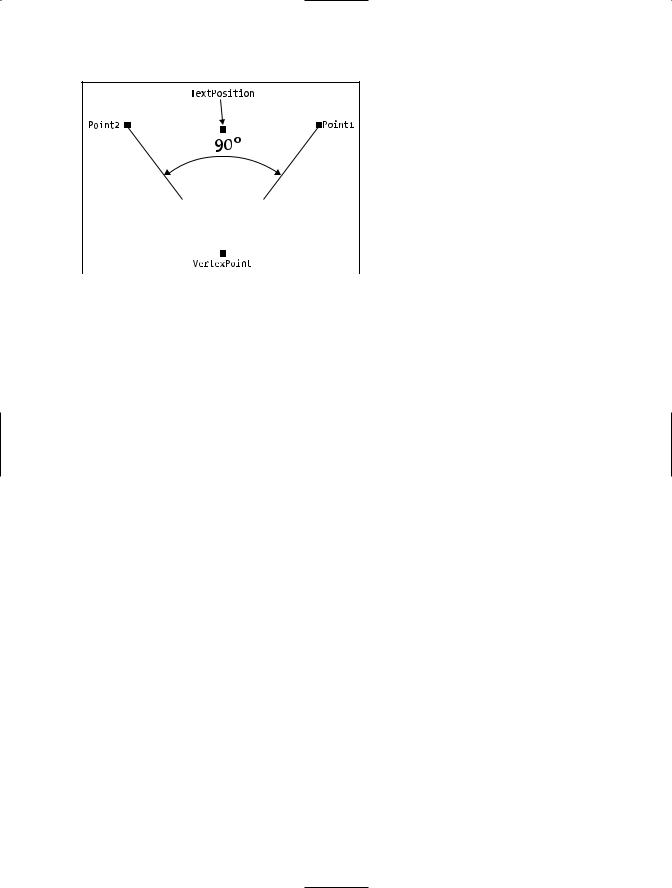
The Dim3PointAngular Object
The Dim3PointAngular object displays the angular distance between three points. You can use the AddDim3PointAngular method to add this type of dimension to a drawing.
Set Dim3PointAngularObject = _
Object.AddDim3PointAngular(VertexPoint, Point1, Point2, _
TextPosition)
Table 11-5 shows the AddDim3PointAngular method’s parameters.
Table 11-5. The AddDim3PointAngular Method’s Parameters
Name |
Data Type |
Description |
VertexPoint |
Variant |
A three-element array of doubles specifying the WCS position of |
|
|
the vertex whose angle is to be measured |
Point1 |
Variant |
A three-element array of doubles specifying the WCS position of |
|
|
one of the end points |
Point2 |
Variant |
A three-element array of doubles specifying the WCS position of |
|
|
the other end point |
TextPosition |
Variant |
A three-element array of doubles specifying the WCS position of |
|
|
the text displaying the angle size |
|
|
|
Figure 11-1 depicts a three-point angular-style dimension.
236 C H A P T E R 1 1 ■ D I M E N S I O N S A N D A N N OTAT I O N S
Figure 11-1. A three-point angular dimension
This code illustrates how to implement the AddDim3PointAngular method:
Public Sub Add3PointAngularDimension()
Dim varAngularVertex As Variant
Dim varFirstPoint As Variant
Dim varSecondPoint As Variant
Dim varTextLocation As Variant
Dim objDim3PointAngular As AcadDim3PointAngular
'Define the dimension
varAngularVertex = ThisDrawing.Utility.GetPoint(, _
"Enter the center point: ") varFirstPoint = ThisDrawing.Utility.GetPoint(varAngularVertex, _
"Select first point: ") varSecondPoint = ThisDrawing.Utility.GetPoint(varAngularVertex, _
"Select second point: ") varTextLocation = ThisDrawing.Utility.GetPoint(varAngularVertex, _
"Pick dimension text location: ")
Set objDim3PointAngular = ThisDrawing.ModelSpace.AddDim3PointAngular( _ varAngularVertex, varFirstPoint, varSecondPoint, varTextLocation)
objDim3PointAngular.Update End Sub
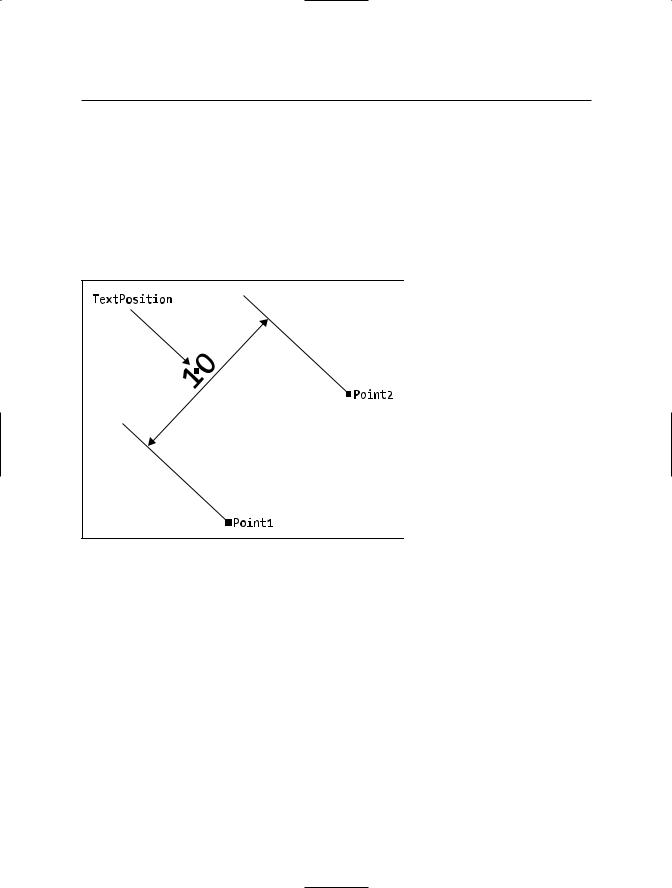
The DimAligned Object
You use the DimAligned object to display the length of a line. Extension lines emanate at right angles from the ends of the line to be measured to the level of the dimension text. You use the AddDimAligned method to add this object to your drawing.
Set DimAlignedObject = Object.AddDimAligned(Point1, Point2, TextPosition)
Table 11-6 shows the AddDimAligned method’s parameters.
C H A P T E R 1 1 ■ D I M E N S I O N S A N D A N N OTAT I O N S |
237 |
Table 11-6. The AddDimAligned Method’s Parameters
Name |
Data Type |
Description |
Point1 |
Variant |
A three-element array of doubles specifying the WCS position of |
|
|
one end of the line to be measured |
Point2 |
Variant |
A three-element array of doubles specifying the WCS position of |
|
|
the other end of the line to be measured |
TextPosition |
Variant |
A three-element array of doubles specifying the WCS position of |
|
|
the text to be displayed |
|
|
|
Figure 11-2 depicts an aligned-style dimension.
Figure 11-2. An aligned dimension
The following example asks users to select the points they would like to dimension. It then uses the AddDimAligned method to add the dimension. Finally, the units are changed to engineering units.
Public Sub AddAlignedDimension() Dim varFirstPoint As Variant Dim varSecondPoint As Variant Dim varTextLocation As Variant
Dim objDimAligned As AcadDimAligned 'Define the dimension
varFirstPoint = ThisDrawing.Utility.GetPoint(, "Select first point: ") varSecondPoint = ThisDrawing.Utility.GetPoint(varFirstPoint, _
"Select second point: ") varTextLocation = ThisDrawing.Utility.GetPoint(, _
"Pick dimension text location: ")