


Chapter 2 Opening a Drawing |
29 |
Working with Templates
A template contains ready-made settings to get you started drawing quickly. These settings include the size of the drawing (called limits), the unit type (such as decimal or feet and inches), and others. An important part of setting standards in an office where people work together on drawings is the creation of a template so that all users work with an identical setup.
Cross- |
In Chapter 5, I explain more of the options available for setting up a drawing. In Chapter 26, |
Reference |
I cover the process of setting standards for drawings. |
|
A template may contain more than just settings — it often contains a complete title block, for example, and may include boilerplate (standardized) text as well.
Customizing the default template
Most people customize the default template to create one or more templates that suit their particular needs. After your templates are created, you don’t have to worry about most settings; they are already available for you and you can quickly start to draw.
To customize acad.dwt or aclt.dwt, follow these steps:
1.Create a drawing based on a template as described in the previous section.
2.Make any changes you want.
3.Click Save on the Standard toolbar.
4.In the Save Drawing As dialog box, click the Files of Type drop-down list box. Choose AutoCAD Drawing Template or AutoCAD LT Drawing Template (*.dwt). In the list of template files, choose the template that you want to customize. Click Save.
5.When asked if you want to replace it, click Yes.
6.In the Template Description dialog box, revise the description as you like, and click OK.
Caution |
If you’re using someone else’s computer, don’t change the templates that come with |
|
AutoCAD or AutoCAD LT without first checking with the computer’s owner. It can be a frus- |
|
trating experience to start a drawing based on a template and find that all the settings have |
|
been changed. Also, if you create new templates, put them in their own folder to avoid los- |
|
ing them when you upgrade or reinstall AutoCAD. |
Creating your own templates
You may want several templates to choose from on a regular basis. For example, you may create drawings of several sizes. AutoCAD and AutoCAD LT let you create as many templates as you want. To create your own templates, either start a drawing based on a template and make the changes you want, or open an existing drawing that already has some of the settings you want and make any further changes you need. Follow these steps:
1.If you start a new drawing based on a template, choose Save from the Standard toolbar. If you open an existing drawing, choose File Save As from the menu.
2.Make any changes you want.

30 |
Part I AutoCAD and AutoCAD LT Basics |
3.In the Save Drawing As dialog box, click the Files of Type drop-down list box. Choose AutoCAD Drawing Template or AutoCAD LT Drawing Template.
4.In the File Name text box, type a name for your template. Click Save.
5.In the Template Description dialog box, enter the description as you want. Click OK.
Tip Name your templates in a way that clearly differentiates them from regular drawings. You may want drawings set up for each of the standard paper sizes (A through E), with a title block in each. Useful names might be tb-a.dwt, tb-b.dwt (tb meaning title block), and so on.
Most AutoCAD and AutoCAD LT users take advantage of these techniques as a standard practice. You can usually make profitable use of a template as the basis for a new drawing.
Opening a Drawing with Default Settings
Occasionally, you may want to open a drawing without any settings. It is actually impossible for a drawing to have no settings at all, but you can open a drawing with the minimum possible presets. You might want to do this if you’re working on someone else’s computer and don’t want to take the time to get rid of a large number of complex settings that aren’t helpful for your work.
To open a drawing with the fewest possible settings, choose File New. Instead of choosing a template, click the arrow to the right of the Open button (see Figure 2-1). Choose one of the following options:
Open with no template — Imperial
Open with no template — Metric
Opening an Existing Drawing
Often you need to open an existing drawing, either to complete it or to make changes. Opening a drawing in AutoCAD or AutoCAD LT is like opening a file in any Windows program. You can find existing drawings by name or by viewing a thumbnail, or preview image, of the drawing.
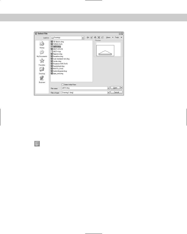
Choose Open from the Standard toolbar. The Select File dialog box appears, as shown in Figure 2-3. In the Look in drop-down list box, choose the drive where your drawing resides. In the main box, double-click the folder you need. Then choose your drawing. The
Preview box enables you to quickly look at the drawing to see if it’s the one you want. (If you don’t see a preview, choose Preview from the Views drop-down list in the dialog box.) Click Open. The drawing opens.
When you open more than one drawing, by default, AutoCAD and AutoCAD LT display only one button on the Windows taskbar. You switch between drawings using the Window item on the drop-down menu. If you want to display a separate taskbar button for each drawing, type taskbar on the command line and press Enter. At the Enter new value for TaskBar <0>: prompt, type 1 and press Enter. Then you can click any drawing’s button to display that drawing.
You can view thumbnail images of all the drawings in a folder in the Select File dialog box (and other dialog boxes that enable you to choose a file) by clicking the Views button and choosing Thumbnails. You can view thumbnails in Windows Explorer in the same way — by clicking the Views button and choosing Thumbnails.
Chapter 2 Opening a Drawing |
31 |
Figure 2-3: The Select File dialog box is equivalent to the Open dialog box in most Windows programs.
You can also use the Places list at the left side of the dialog box to find drawings. The Places list is described in Chapter 1.
Using other ways to open drawings
You can double-click a drawing in Windows Explorer to open it. If AutoCAD or AutoCAD LT is not running, Windows loads the program and the drawing as well. If AutoCAD or AutoCAD LT is running and a drawing is active, the drawing opens as a second drawing within the program.
You can also open a drawing from the DesignCenter — a feature for managing both drawing files and many of their components. First, choose DesignCenter from the Standard
toolbar. The DesignCenter palette opens, displaying an Explorer-like list of drawings in the left pane. (If you don’t see the list of drawings, click the Tree View Toggle button on the
DesignCenter toolbar.) Navigate to the folder containing the drawing and choose the drawing’s folder in the left pane. The drawings in the folder are listed in the right pane. Right-click the drawing of your choice and choose Open in Application Window. For more information on
the DesignCenter, see Chapter 26.
You can open a drawing using the Sheet Set Manager (AutoCAD only). I cover sheet sets in Chapter 26.
Using shortcuts in dialog boxes
You can use several shortcuts when working in dialog boxes that open or save files, as follows:
Double-click the drawing file to open it immediately without clicking Open.
Click the Views drop-down list. Choose List to see a simple list. Choose Details to see the file size and the last date and time the file was saved.
Right-click inside the dialog box to open a shortcut menu with more options.
Click the name of a drawing to highlight it and then click it once more to rename it (but don’t double-click it — that opens the drawing).
32 |
Part I AutoCAD and AutoCAD LT Basics |
On the |
The drawing used in the following exercise on opening a drawing, ab01-01.dwg, is in the |
CD-ROM |
Results folder of the AutoCAD 2006 and AutoCAD LT 2006 Bible CD-ROM. Place the |
|
CD-ROM in your CD-ROM drive. |
STEPS: Opening a Drawing
1.If AutoCAD or AutoCAD LT is not open, start the program.
2. Click Open on the Standard toolbar.
3.In the Select File dialog box, choose the drive for your CD-ROM in the Look in dropdown list box.
4.In the main box, double-click the Results folder.
5.In the main box, click ab01-01.dwg.
6.Click Open. The drawing opens. Keep this drawing open for the next exercise.
Using an Existing Drawing as a Prototype
Although a template can be very useful, if you plan to use the objects and settings in a drawing only a few times, you can simply use one drawing as a prototype for other drawings. You may often need to draw a series of related drawings — perhaps several related electrical schematics or a group of similar apartments in an apartment complex. When a significant part of the first drawing is applicable to subsequent drawings, don’t start over — open an existing drawing, and immediately save it under a new name, as described in the next section. Make the necessary changes and resave the drawing.
Saving a Drawing Under a New Name
Whether you want to use an existing drawing as a prototype or simply make a copy of a drawing, you need to save the drawing under a new name. First open the drawing and then choose File Save As.
In the Save Drawing As dialog box, type a new name in the File Name text box. Then click Save. You may also want to change the location of the new drawing by changing the folder in the Save In drop-down list box.
On the |
The drawing used in the following exercise saving a drawing under a new name, abqs- |
CD-ROM |
01.dwg, is in the Results folder of the AutoCAD 2006 and AutoCAD LT 2006 Bible |
|
CD-ROM. |
STEPS: Saving a Drawing Under a New Name
1.If you did the exercise in the Quick Start chapter, open abqs-01.dwg from the folder where you saved it. (I suggested the My Documents or the AutoCAD Bible folder.) Otherwise, open the drawing from the Results folder of the AutoCAD 2006 and AutoCAD LT 2006 Bible CD-ROM.
Chapter 2 Opening a Drawing |
33 |
2.Choose File Save As. The Save Drawing As dialog box opens.
3.In the File Name text box, change the file name to ab02-01.dwg. Choose your AutoCAD Bible folder and click Save.
4.At the bottom of the drawing area, click the Model tab.
5.From the Layer Control drop-down list on the Layers toolbar, choose the DETAILING layer.
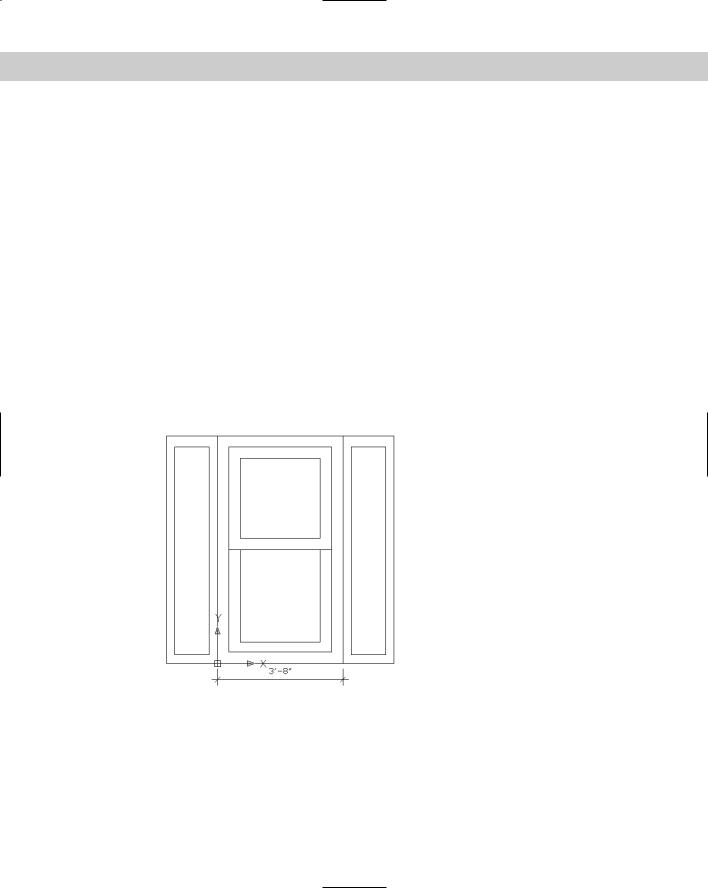
6.Choose Rectangle from the Draw toolbar. Follow the prompts, entering the text in the Dynamic Input tooltip:
Specify first corner point or [Chamfer/Elevation/Fillet/Thickness/Width]: -15,3 Specify other corner point or [Dimensions]: 12,6’1
7.Again, choose Rectangle from the Draw toolbar. Leave the crosshairs to the right of the window and follow the prompts:
Specify first corner point or [Chamfer/Elevation/Fillet/Thickness/Width]: 3’11,3 Specify other corner point or [Dimensions]: 12,6’1
Your drawing should look like Figure 2-4.
Figure 2-4: The window with added detailing.
8.Click the drawing Close box, which is just below the application Close box.
9.Because you haven’t saved the changes to the drawing, a message asks if you want to save them.
10.Click Yes. AutoCAD or AutoCAD LT saves and closes the drawing.
11.Click the application’s Close box (X) to close AutoCAD or AutoCAD LT.