

- •Contents
- •Contents at a Glance
- •Acknowledgments
- •Preface
- •Is This Book for You?
- •How This Book Is Organized
- •How to Use This Book
- •Doing the Exercises
- •Conventions Used in This Book
- •What the Icons Mean
- •About the CD-ROM
- •Other Information
- •Contacting the Author
- •Foreword
- •Credits
- •About the Author
- •Summary
- •AutoCAD’s Advantages
- •Comparing AutoCAD and AutoCAD LT
- •Starting AutoCAD and AutoCAD LT
- •Creating a New Drawing
- •Using the AutoCAD and AutoCAD LT Interface
- •Creating a New Folder
- •Using the Interface
- •Saving a Drawing
- •Closing a Drawing and Exiting from AutoCAD and AutoCAD LT
- •Summary
- •Creating a New Drawing from a Template
- •Working with Templates
- •Opening a Drawing with Default Settings
- •Opening an Existing Drawing
- •Using an Existing Drawing as a Prototype
- •Saving a Drawing Under a New Name
- •Summary
- •The Command Line and Dynamic Input
- •Command Techniques
- •Of Mice and Pucks
- •Getting Help
- •Summary
- •Typing Coordinates
- •Displaying Coordinates
- •Picking Coordinates on the Screen
- •Overriding Coordinate Settings
- •Locating Points
- •Summary
- •Choosing Unit Types
- •Drawing Limits
- •Understanding Scales
- •Creating a Title Block
- •Specifying Common Setup Options
- •Customizing with the MVSETUP Command
- •Using the Setup Wizards
- •Summary
- •Using the LINE Command
- •Drawing Rectangles
- •Drawing Polygons
- •Creating Construction Lines
- •Creating Rays
- •Summary
- •Drawing Circles
- •Drawing Arcs
- •Creating Ellipses and Elliptical Arcs
- •Making Donuts
- •Placing Points
- •Summary
- •Panning
- •Using the ZOOM Command
- •Using Aerial View
- •Saving Named Views
- •Working with Tiled Viewports
- •Using Snap Rotation
- •Understanding User Coordinate Systems
- •Creating Isometric Drawings
- •Summary
- •Editing a Drawing
- •Selecting Objects
- •Summary
- •Copying and Moving Objects
- •Resizing Commands
- •Using Construction Commands
- •Creating a Revision Cloud
- •Hiding Objects with a Wipeout
- •Double-Clicking to Edit Objects
- •Grips
- •Editing with the Properties Palette
- •Selection Filters
- •Groups
- •Summary
- •Working with Layers
- •Changing Object Color, Linetype, and Lineweight
- •Working with Linetype Scales
- •Importing Layers and Linetypes from Other Drawings
- •Matching Properties
- •Summary
- •Drawing-Level Information
- •Object-Level Information
- •Measurement Commands
- •AutoCAD’s Calculator
- •Summary
- •Creating Single-Line Text
- •Understanding Text Styles
- •Creating Multiline Text
- •Creating Tables
- •Inserting Fields
- •Managing Text
- •Finding Text in Your Drawing
- •Checking Your Spelling
- •Customizing the spelling dictionary
- •Summary
- •Working with Dimensions
- •Drawing Linear Dimensions
- •Drawing Aligned Dimensions
- •Creating Baseline and Continued Dimensions
- •Dimensioning Arcs and Circles
- •Dimensioning Angles
- •Creating Ordinate Dimensions
- •Drawing Leaders
- •Using Quick Dimension
- •Editing Dimensions
- •Summary
- •Understanding Dimension Styles
- •Defining a New Dimension Style
- •Changing Dimension Styles
- •Creating Geometric Tolerances
- •Summary
- •Creating and Editing Polylines
- •Drawing and Editing Splines
- •Creating Regions
- •Creating Boundaries
- •Creating Hatches
- •Creating and Editing Multilines
- •Creating Dlines
- •Using the SKETCH Command
- •Digitizing Drawings with the TABLET Command
- •Summary
- •Preparing a Drawing for Plotting or Printing
- •Creating a Layout in Paper Space
- •Working with Plot Styles
- •Plotting a Drawing
- •Summary
- •Combining Objects into Blocks
- •Inserting Blocks and Files into Drawings
- •Managing Blocks
- •Creating and Using Dynamic Blocks
- •Using Windows Features
- •Working with Attributes
- •Summary
- •Understanding External References
- •Editing an Xref within Your Drawing
- •Controlling Xref Display
- •Managing Xrefs
- •Summary
- •Preparing for Database Connectivity
- •Connecting to Your Database
- •Linking Data to Drawing Objects
- •Creating Labels
- •Querying with the Query Editor
- •Working with Query Files
- •Summary
- •Working with 3D Coordinates
- •Using Elevation and Thickness
- •Working with the User Coordinate System
- •Summary
- •Working with the Standard Viewpoints
- •Using DDVPOINT
- •Working with the Tripod and Compass
- •Displaying a Quick Plan View
- •Shading Your Drawing
- •Using 3D Orbit
- •Using Tiled Viewports
- •Defining a Perspective View
- •Laying Out 3D Drawings
- •Summary
- •Drawing Surfaces with 3DFACE
- •Drawing Surfaces with PFACE
- •Creating Polygon Meshes with 3DMESH
- •Drawing Standard 3D Shapes
- •Drawing a Revolved Surface
- •Drawing an Extruded Surface
- •Drawing Ruled Surfaces
- •Drawing Edge Surfaces
- •Summary
- •Drawing Standard Shapes
- •Creating Extruded Solids
- •Drawing Revolved Solids
- •Creating Complex Solids
- •Sectioning and Slicing Solids
- •Using Editing Commands in 3D
- •Editing Solids
- •Listing Solid Properties
- •Summary
- •Understanding Rendering
- •Creating Lights
- •Creating Scenes
- •Working with Materials
- •Using Backgrounds
- •Doing the Final Render
- •Summary
- •Accessing Drawing Components with the DesignCenter
- •Accessing Drawing Content with Tool Palettes
- •Setting Standards for Drawings
- •Organizing Your Drawings
- •Working with Sheet Sets
- •Maintaining Security
- •Keeping Track of Referenced Files
- •Handling Errors and Crashes
- •Managing Drawings from Prior Releases
- •Summary
- •Importing and Exporting Other File Formats
- •Working with Raster Images
- •Pasting, Linking, and Embedding Objects
- •Summary
- •Sending Drawings
- •Opening Drawings from the Web
- •Creating Object Hyperlinks
- •Publishing Drawings
- •Summary
- •Working with Customizable Files
- •Creating Keyboard Shortcuts for Commands
- •Customizing Toolbars
- •Customizing Tool Palettes
- •Summary
- •Creating Macros with Script Files
- •Creating Slide Shows
- •Creating Slide Libraries
- •Summary
- •Creating Linetypes
- •Creating Hatch Patterns
- •Summary
- •Creating Shapes
- •Creating Fonts
- •Summary
- •Working with the Customization File
- •Customizing a Menu
- •Summary
- •Introducing Visual LISP
- •Getting Help in Visual LISP
- •Working with AutoLISP Expressions
- •Using AutoLISP on the Command Line
- •Creating AutoLISP Files
- •Summary
- •Creating Variables
- •Working with AutoCAD Commands
- •Working with Lists
- •Setting Conditions
- •Managing Drawing Objects
- •Getting Input from the User
- •Putting on the Finishing Touches
- •Summary
- •Understanding Local and Global Variables
- •Working with Visual LISP ActiveX Functions
- •Debugging Code
- •Summary
- •Starting to Work with VBA
- •Writing VBA Code
- •Getting User Input
- •Creating Dialog Boxes
- •Modifying Objects
- •Debugging and Trapping Errors
- •Moving to Advanced Programming
- •Summary
- •A Final Word
- •Installing AutoCAD and AutoCAD LT
- •Configuring and Using Workspaces
- •Configuring AutoCAD
- •Starting AutoCAD Your Way
- •Configuring a Plotter
- •Discovering AutoCAD and AutoCAD LT
- •Accessing Technical Support
- •Autodesk User Groups
- •Internet Resources
- •System Requirements
- •Using the CD-ROM with Microsoft Windows
- •What’s on the CD-ROM
- •Troubleshooting
- •Index
622 Part III Working with Data
3.To add a record, right-click any record (row) header and choose Add New Record. AutoCAD moves you to the end of the records with a space for a new record. Type the following, tabbing between each column:
8665-023-018 |
WELDING ROD - .05 DIA S.S. |
B |
P |
FT |
4.I don’t recommend saving the changes to the database because you may want to do this exercise again in the future. Right-click the grid header (in the upper-left corner of the database) and choose Restore. AutoCAD closes the Data Table.
5.Keep the drawing open for the next exercise.
Linking Data to Drawing Objects
The main purpose of using data connectivity is to link data to objects in your drawing. A row of data contains information about the real-life object that objects in your drawing represent. By connecting a row of data to an object or objects in your drawing, you can:
View information about the real-life object while in your drawing, such as price, source, next service date, and so on.
Update a drawing based on changes in the database or vice versa, to keep your drawings and your database synchronized.
Display a label containing data information next to a drawing object.
Creating a link template
When AutoCAD creates a link, it associates an object or objects with a row in your database. To do so, AutoCAD needs to know which field (column) to look in to identify the row. For example, let’s say you want to link price information to some objects. However, several rows may contain the same price information. If you provide a field that contains no duplicate data, AutoCAD can always locate the required row. If AutoCAD finds two rows with the same data, it accesses the first row. It makes sense, therefore, to be careful to choose a column that contains no duplicate values. If your data doesn’t contain such a column, most DBMSs can create an index field that ensures that each row is unique.
A link template identifies which fields are associated with a link between the data and a drawing object. A link template also identifies your database. After you create a link template, you can open your data directly from the template, which is listed in the dbConnect window.
If you want to associate data from more than one database table to a single object, you may need to create more than one link template for an object.
To create a link template, follow these steps:
1.Choose dbConnect Templates New Link Template.
2.If you haven’t already opened a data table, AutoCAD opens the Select Data Object dialog box. Choose a table and click Continue.
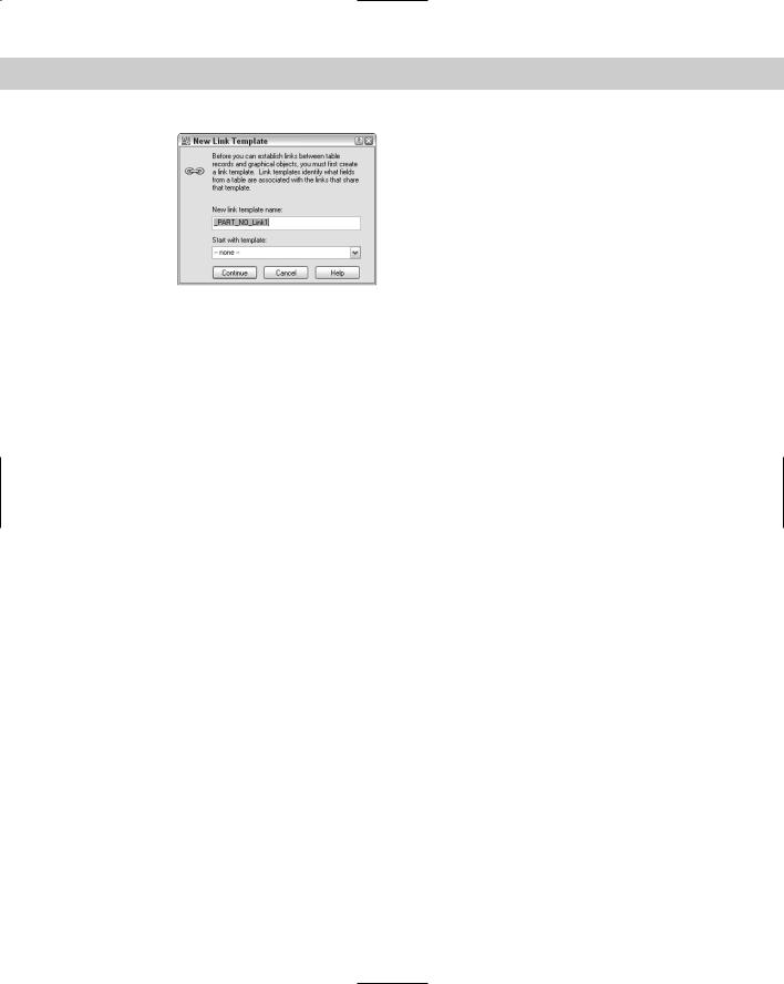
3.In the New Link Template Name text box of the New Link Template dialog box, shown in Figure 20-10, type a name for the link template. AutoCAD assigns an automatic name using the name of the data source and Link1, Link2, and so on. You can use that name or type your own. If you have a previous link template that you want to use as a basis for the new template, choose it from the Start with Template drop-down list. Click Continue.
Chapter 20 Working with External Databases |
623 |
Figure 20-10: The New Link
Template dialog box.
4.In the Link Template dialog box, check a key field. If the key field that you choose contains any duplicate rows, you should choose a second key field.
5.Click OK. AutoCAD creates the link template, which is added to the dbConnect window beneath the current drawing.
You’re now ready to link data with drawing objects.
If the structure of your database changes dramatically, you may need to edit a link template. For example, a field that contained no duplicate entries might now contain some. Other changes requiring a change in the template would be a change in the name or length of a field. To edit a link template:
1.Connect to the desired database table.
2.Choose dbConnect Templates Edit Link Template.
3.In the Select a Database Object dialog box, choose a link template.
4.Click Continue.
5.Check one (or more) of the key fields and click OK.
You can also delete a link template by choosing dbConnect Templates Delete Link Template.
This exercise requires that you have completed the previous exercises in this chapter.
STEPS: Creating a Link Template
1.Continue with ab20-01.dwg from the previous exercise. In the dbConnect window, right-click “PART NO” and choose Edit Table to open the Data Table window.
2.Choose dbConnect Templates New Link Template.
3.Select the PART_NO table and click Continue.
4.In the New Link Template dialog box, use AutoCAD’s suggested name, PART_NO_Link1. Click Continue.
5.In the Link Template dialog box, check PART_NO. This column contains no duplicate rows.

624 Part III Working with Data
6.Click OK to return to the drawing. You see the new link template with a chain-link icon in the dbConnect window just under the name of the open drawing.
7.Save your drawing. Leave it open to continue with the next exercise.
You’re now ready to link drawing objects to your database.
Creating a link
You can link a drawing object to as many records in a database as you want, and you can link one database record to several drawing objects. For example, you may want to link a record containing part-number information to the part in the drawing. However, that part may be made up of a number of objects, such as lines, arcs, and circles. You can link the record to all of those objects in your drawing that make up the part. On the other hand, if you have a database of office equipment, you may attach a row representing telephone numbers and telephones to an object in your drawing representing a phone. However, if someone has a two-line phone, you may need to attach two rows to that one telephone object in your drawing.
Here’s how to create a link:
1.Open a Data View window that has a defined link template and choose a link template from the Select a Link Template drop-down list at the top of the window.
2.Select one or more records that you want to link to your drawing.
3.Choose Data View Link and Label Settings Create Links.
4.Choose Data View Link! (You can also choose Link in the Data View window.)
5.AutoCAD returns you to your drawing. Select one or more objects and press Enter to end object selection.
AutoCAD provides a message on the command line, for example: 1 Record(s) linked with 1 Object(s). You now have a link between your data and your drawing.
Caution |
If you create a link between a drawing object and a row and in a later session of AutoCAD |
|
edit that object without connecting to the database table, the link information may become |
|
corrupted. |
You can delete a link by selecting a linked object and right-clicking in the drawing area. From the shortcut menu, choose Link Delete Link.
Viewing linked objects and rows
After you create a link, you need to be able to see which rows are linked to which objects before you can make decisions regarding either the data or the drawing objects. You can view the link from either side. That is, you can select an object and see which row or rows it is linked to or you can select a row and have AutoCAD select the object or objects to which it’s linked. In both cases, you need to have a Data View table displayed.
To find out which row an object is linked to, select one or more objects. Then choose Data View View Linked Records. AutoCAD highlights the row or rows that are linked to the selection set of objects. Later in this section, I explain how to customize the display of a row or rows.
To find out which object a row is linked to, select one or more records. Choose
Data View View Linked Objects. AutoCAD pans, zooms (or does both so that you can see the objects in the center of the screen), and selects them. Later in this section, I explain how to customize the panning and zooming.

Chapter 20 Working with External Databases |
625 |
|
You’ll find that the Data View window obscures your drawing. You can drag it to the bottom |
|
of your screen, resize it, or dock it. |
Tip |
When you use View Linked Objects, the selected objects form a selection set. You can then |
|
use the results with other commands that allow prior selection of objects. For commands |
|
that you must execute before selecting objects, type p at the Select objects: prompt |
|
to use the Previous option and get the selection set. |
If you want to move from object to object or row to row to view your links one after another, you should use Auto-View. The Auto-View feature automatically highlights either objects when you choose a row in the Data View window or rows when you choose objects in your drawing. However, you can work from only one side of the equation — either rows or objects — at a time. Here’s how it works:
To automatically select linked objects when you select a row, choose Data View AutoView Linked Objects (or use the AutoView Linked Objects in Drawing button in the Data View window). Then select a record (or records) by clicking the row header(s)
in the Data View window. AutoCAD highlights the linked objects. You can continue to select different records to highlight their linked objects. Choose Auto-View Linked Objects (or click the button) again to turn off Auto-View.
To automatically select linked rows when you select an object, choose Data View AutoView Linked Records (or use the AutoView Linked Records in Data View button in the Data View window). Then select an object (or objects). AutoCAD highlights the linked rows. You can continue to select different objects to highlight their linked rows. Choose Auto-View Linked Records (or click the button) again to turn off Auto-View.
When you’re in Auto-View, you can’t select records. If you click another record’s row header to create a link, AutoCAD just tells you 0 Object(s) found matching 0 selected Record(s). Be sure to turn off Auto-View when you go on to another task.
You can customize how AutoCAD displays linked rows and how AutoCAD pans (AutoPan) and zooms (AutoZoom) to display selected objects. Choose Data View Settings. In the Record Indication Settings section of the Data View and Query Options dialog box, choose either Show Only Indicated Records or Show All Records — Select Indicated Records (the default). You can also choose the highlight color. To set AutoPan and AutoZoom, use the AutoPan and Zoom section of the same dialog box. Uncheck Automatically Pan Drawing and Automatically Zoom Drawing if you don’t want this feature. When Automatically Zoom Drawing is checked, you can also choose a zoom percentage. You can choose from 20 to 90 percent. The default, 50 percent, means that the height (or width, if less) of the extents of the zoomed area is 50 percent of the drawing area. Click OK after you finish using the dialog box.
Editing links
After you create links in your drawing, you need to be careful how you edit your database from within AutoCAD. For example, you don’t want to inadvertently delete a record that is linked to an object.
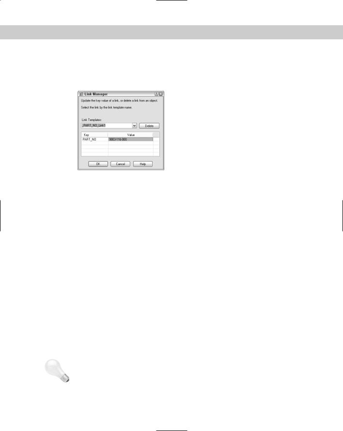
You may need to edit the key value assigned to a linked object. For example, your company may change the part-numbering scheme or you may have simply assigned the wrong part number to an object. The Link Manager enables you to edit key values for linked objects. Follow these steps:
1.Choose dbConnect Links Link Manager to open the Link Manager, shown in Figure 20-11. You can also select a linked object, right-click in the drawing area, and choose Link Link Manager.
626 Part III Working with Data
2.At the Select an object: prompt, select an object.
3.In the Link Manager, choose the Link Template that you want to work with from the drop-down list.
Figure 20-11: The Link Manager enables you to edit key value data for its linked object.
4.In the Value column, type a new value, such as a new part number.
5.Click OK.
AutoCAD updates the link.
You can also click the Delete button to delete the object’s link.
Exporting link information
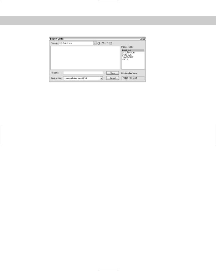
You can export a list of links and the handle of the associated links’ objects. A handle is a unique name that AutoCAD gives to each object in the drawing. (To view an object’s handle, select it and choose Tools Inquiry List.) You can export the reports in the same format as your database (called the native format) or in spaceor comma-delimited formats. You might use these reports to keep track of how many objects are linked to a row because the exported information tells you how many instances a drawing contains of a record in a database. For example, if your database lists configurations of desktop computers and you’ve linked each person’s computer to the appropriate row in the database, the list will let you know how many people have each configuration.
Follow these steps to export links:
1.Choose dbConnect Links Export Links.
2.At the Select objects: prompt, choose the objects whose links you want to export. When you complete object selection, AutoCAD opens the Export Links dialog box, shown in Figure 20-12.
Tip You can select the entire drawing (type all at the Select Objects: prompt) and AutoCAD finds just the linked objects.
Chapter 20 Working with External Databases |
627 |
Figure 20-12: The Export Links dialog box.
3.In the Include Fields section, select the fields that you want to include.
4.In the Save In drop-down list, navigate to the folder where you want to save the file.
5.In the Save as Type drop-down list, choose one of the three options: comma-delimited format, space-delimited format, or native database format.
6.In the File Name text box, type a name for the file.
7.Click Save.
AutoCAD creates the file.
You can use this file to create a schedule of objects with links — but it takes some work. The comma-delimited format seems to work better than the space-delimited format. You’ll probably want to edit the file first to remove the object handles. You can open the Multiline Text Editor and click Import Text to import the output file into your drawing. You can also open the output file, copy it to the Clipboard, and paste it into your drawing. The Import Text method enables you to format the text as you would any multiline text but takes some experimenting to set up in the proper columns. You can also import the file into a spreadsheet and format it before importing it into your drawing. If you used the native format, you can open it in your DBMS, format it, and import it into your drawing. (See Chapter 27 for more information on importing files.)
STEPS: Creating and Viewing Links
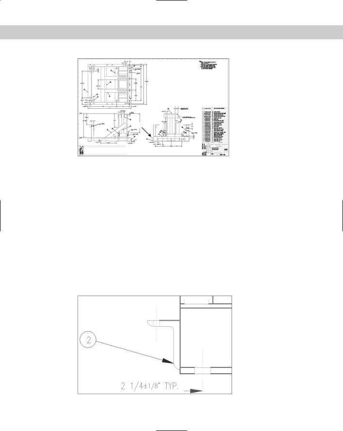
1.You should have ab20-01.dwg open from the previous exercise. The Data View window is open with the database visible. The PART_NO_Link1 link template is current. You can see the entire drawing in Figure 20-13.
2.To locate the record that you need, in the Data View window click the left-most arrow next to the horizontal scroll bar to move to the first record. Choose Data View Find. In the Find dialog box, type 9003-242-001. The direction should be down. Click Find Next. AutoCAD finds the record. Close the Find dialog box by clicking its Cancel button.
3.Click the row’s header (the arrow to the left of the row) to select the entire row.
4.Choose Data View Link and Label Settings Create Links. The Create Links menu item may already be checked.
5.Choose Data View Link!
628 Part III Working with Data
1
Figure 20-13: This drawing of a base assembly for a commercial washing machine has objects that can be linked to the database of parts.
Thanks to Robert Mack of The Dexter Company, Fairfield, Iowa, for this drawing.
6.AutoCAD returns you to your drawing. Use the Zoom Window to zoom into the area marked 1 in Figure 20-13.
7.Select all of the objects that make up the angle bracket indicated by 1 in Figure 20-13 (and which the drawing itself labels as 2), as shown in Figure 20-14. Include the two cyan hidden lines representing the hole, but not the yellow centerline. Don’t select the vertical line on the right of the angle, which belongs to another part. Press Enter to end the selection. AutoCAD returns you to the Data View table and displays 1 Record(s) linked with 8 Object(s) on the command line.
8.The linked row is still highlighted in yellow. Make sure that the arrow cursor in the row header points to the highlighted row. (AutoCAD moves it down one so that you can work on the next row.) To view the objects connected to the row, choose Data View View Linked Objects. Drag the Data View window to the bottom of the screen so that you can see the drawing (or dock it). The objects that you selected in Step 7 are selected.
Figure 20-14: The horizontal angle.